EP2267655A2 - Appareil et procédé de traitement d'images - Google Patents
Appareil et procédé de traitement d'images Download PDFInfo
- Publication number
- EP2267655A2 EP2267655A2 EP10165001A EP10165001A EP2267655A2 EP 2267655 A2 EP2267655 A2 EP 2267655A2 EP 10165001 A EP10165001 A EP 10165001A EP 10165001 A EP10165001 A EP 10165001A EP 2267655 A2 EP2267655 A2 EP 2267655A2
- Authority
- EP
- European Patent Office
- Prior art keywords
- image
- tone conversion
- region
- reference region
- contrast
- Prior art date
- Legal status (The legal status is an assumption and is not a legal conclusion. Google has not performed a legal analysis and makes no representation as to the accuracy of the status listed.)
- Withdrawn
Links
Images


Classifications
-
- G—PHYSICS
- G06—COMPUTING OR CALCULATING; COUNTING
- G06T—IMAGE DATA PROCESSING OR GENERATION, IN GENERAL
- G06T5/00—Image enhancement or restoration
- G06T5/40—Image enhancement or restoration using histogram techniques
-
- H—ELECTRICITY
- H04—ELECTRIC COMMUNICATION TECHNIQUE
- H04N—PICTORIAL COMMUNICATION, e.g. TELEVISION
- H04N5/00—Details of television systems
- H04N5/30—Transforming light or analogous information into electric information
- H04N5/32—Transforming X-rays
-
- G—PHYSICS
- G06—COMPUTING OR CALCULATING; COUNTING
- G06T—IMAGE DATA PROCESSING OR GENERATION, IN GENERAL
- G06T5/00—Image enhancement or restoration
- G06T5/90—Dynamic range modification of images or parts thereof
- G06T5/94—Dynamic range modification of images or parts thereof based on local image properties, e.g. for local contrast enhancement
-
- H—ELECTRICITY
- H04—ELECTRIC COMMUNICATION TECHNIQUE
- H04N—PICTORIAL COMMUNICATION, e.g. TELEVISION
- H04N23/00—Cameras or camera modules comprising electronic image sensors; Control thereof
- H04N23/30—Cameras or camera modules comprising electronic image sensors; Control thereof for generating image signals from X-rays
-
- H—ELECTRICITY
- H04—ELECTRIC COMMUNICATION TECHNIQUE
- H04N—PICTORIAL COMMUNICATION, e.g. TELEVISION
- H04N23/00—Cameras or camera modules comprising electronic image sensors; Control thereof
- H04N23/80—Camera processing pipelines; Components thereof
- H04N23/81—Camera processing pipelines; Components thereof for suppressing or minimising disturbance in the image signal generation
-
- H—ELECTRICITY
- H04—ELECTRIC COMMUNICATION TECHNIQUE
- H04N—PICTORIAL COMMUNICATION, e.g. TELEVISION
- H04N5/00—Details of television systems
- H04N5/44—Receiver circuitry for the reception of television signals according to analogue transmission standards
- H04N5/57—Control of contrast or brightness
-
- G—PHYSICS
- G06—COMPUTING OR CALCULATING; COUNTING
- G06T—IMAGE DATA PROCESSING OR GENERATION, IN GENERAL
- G06T2207/00—Indexing scheme for image analysis or image enhancement
- G06T2207/10—Image acquisition modality
- G06T2207/10016—Video; Image sequence
-
- G—PHYSICS
- G06—COMPUTING OR CALCULATING; COUNTING
- G06T—IMAGE DATA PROCESSING OR GENERATION, IN GENERAL
- G06T2207/00—Indexing scheme for image analysis or image enhancement
- G06T2207/10—Image acquisition modality
- G06T2207/10116—X-ray image
-
- G—PHYSICS
- G06—COMPUTING OR CALCULATING; COUNTING
- G06T—IMAGE DATA PROCESSING OR GENERATION, IN GENERAL
- G06T2207/00—Indexing scheme for image analysis or image enhancement
- G06T2207/20—Special algorithmic details
- G06T2207/20004—Adaptive image processing
- G06T2207/20012—Locally adaptive
-
- G—PHYSICS
- G06—COMPUTING OR CALCULATING; COUNTING
- G06T—IMAGE DATA PROCESSING OR GENERATION, IN GENERAL
- G06T2207/00—Indexing scheme for image analysis or image enhancement
- G06T2207/20—Special algorithmic details
- G06T2207/20092—Interactive image processing based on input by user
- G06T2207/20104—Interactive definition of region of interest [ROI]
-
- G—PHYSICS
- G06—COMPUTING OR CALCULATING; COUNTING
- G06T—IMAGE DATA PROCESSING OR GENERATION, IN GENERAL
- G06T2207/00—Indexing scheme for image analysis or image enhancement
- G06T2207/30—Subject of image; Context of image processing
- G06T2207/30004—Biomedical image processing
-
- H—ELECTRICITY
- H04—ELECTRIC COMMUNICATION TECHNIQUE
- H04N—PICTORIAL COMMUNICATION, e.g. TELEVISION
- H04N5/00—Details of television systems
- H04N5/14—Picture signal circuitry for video frequency region
- H04N5/20—Circuitry for controlling amplitude response
Definitions
- the present invention relates to an X-ray image processing method for transforming an X-ray image into an output image with optimal tones. More specifically, the present invention relates to an image processing method (i.e. a tone-mapping method) and an image processing apparatus for creating a tone conversion curve to define the contrast of the output image, the created tone conversion curve incorporating at least in part a tone conversion curve of a previous image.
- an image processing method i.e. a tone-mapping method
- an image processing apparatus for creating a tone conversion curve to define the contrast of the output image, the created tone conversion curve incorporating at least in part a tone conversion curve of a previous image.
- Tone conversion that optimizes an observation region of the X-ray image is performed to improve the diagnostic performance by physicians.
- extraction of an observation region from the X-ray image that is more robust to noise and motion has been proposed.
- a sigmoid function has been used as a tone curve to optimize the output image of this region.
- X-ray variation refers to variability in the amount of X-rays that are produced even under constant imaging conditions, and to changes in imaging conditions because of X-ray manipulation or control.
- Object variation may refer, for instance, to the lung field moving in and out of the imaging region as a result of breathing, or to the injection of a contrast dye.
- Example methods of analyzing objects include a method that involves creating histograms from pixel values of input images, extracting minimum and maximum values, and filtering these values temporally (e.g., see Japanese Patent No. 3334321 ). Filtering the minimum and maximum values temporally enables sensitivity to contrast variation to be suppressed and stabilized.
- Example methods for controlling tone conversion include a method that involves detecting a scene change by analysing an input image, and merging a newly created tone conversion curve with a past tone conversion curve based on the time required for the scene change (e.g., see Japanese Patent No. 4050547 ). According to this method, sensitivity to contrast variation can be suppressed and stabilized by temporally filtering tone conversion curves.
- a method that suppresses contrast variation in the region being closely observed while demonstrating contrast variation over the image as a whole is desired. Furthermore, there are many instances where, in the case where the tone conversion curve is controlled based on the time required for a scene change within the image sequence, it is desirable to control the variation in contrast irrespective of the time required for that scene change.
- an image processing method as defined in claims 1 to 9 is provided.
- an image processing apparatus as defined in claim 10 or 11 is provided.
- FIG. 1 is a block diagram showing an example of a hardware configuration of an image processing apparatus according to the present invention.
- FIG. 2 is a block diagram showing a detailed configuration of an image processing unit 104 shown in FIG. 1 .
- FIGS. 3A and 3B show histograms of pixel values in two X-ray image frames.
- FIGS. 4A and 4B show characteristics of merged tone conversion curves.
- FIG. 5 is a graph illustrating a feedback coefficient according to the present invention.
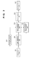
- FIG. 6 is a flowchart showing image processing in a First Embodiment.
- FIGS. 7A and 7B are graphs showing merged tone conversion curves and feedback coefficients in a reference region.
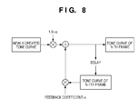
- FIG. 8 is a schematic diagram showing a process of merging tone conversion curves based on the feedback coefficient.
- FIG. 9 is a flowchart showing image processing in a Second Embodiment.
- a method for creating an image in which sensitivity to contrast variation is suppressed in a region being observed by setting a feedback coefficient for the region being observed to a large value, and in which contrast variation is reflected (i.e. is taken account of) in the remaining region by setting the feedback coefficient for the remaining region to a small value.
- reflected what is meant is that the contrast variation is somehow acknowledged in the non-reference region. For instance, if display processing is completed, the contrast variation is displayed and thus the contrast variation that has occurred is reflected in the display. On the other hand, if full display processing is not performed and only internal processing is performed that does not give rise to a display, the contrast variation is calculated and taken account of in the processing of the merged tone conversion curve.
- an image processing apparatus 100 includes a Central Processing Unit, CPU 101; a Read-Only Memory, ROM 102; a Random-Access Memory, RAM 103; an image processing unit 104; a hard disk drive, HDD 105; an input/output interface, I/F 106 and a network interface, I/F 107.
- the constituent elements 101 to 107 are connected via a system bus 108.
- the CPU 101 controls the overall apparatus in accordance with computer programs stored in the ROM 102, the HDD 105, and the like.
- the ROM 102 is a memory that stores startup programs, control data, and the like.
- the RAM 103 is a memory in which programs are developed when the CPU 101 executes processing, with various tables, a work region, and the like, being defined.
- the image processing unit 104 performs image processing such as tone conversion (detailed later) on input X-ray images.
- the image processing unit 104 is implemented as a dedicated image processing board, but may be realized as a software module. In other words, the image processing unit 104 may be appropriately implemented depending on purpose.
- the HDD 105 stores an operating system (OS), application software and the like.
- the input/output I/F 106 is an interface with an output apparatus such as a display and an input apparatus such as a keyboard or a mouse.
- the network I/F 107 is an interface with an external network such as local area network (LAN).
- LAN local area network
- the image processing unit 104 is connected to a network 140 of the X-ray imaging system.
- This network 140 may constitute a control area network (CAN), or it may constitute an optical fibre.
- An X-ray generation apparatus 110, a medical monitor 120 and an X-ray sensor (planar detector) 130 are connected to the network 140.
- a picture archiving and communication system (PACS) and an intra-modality hard disk apparatus for storing X-ray images may also be connected to the network 140. Imaging of an object may be controlled by issuing commands from the image processing unit 104 to the X-ray generation apparatus 110 or to the X-ray sensor 130 in the X-ray imaging system.
- PPS picture archiving and communication system
- Imaging of an object may be controlled by issuing commands from the image processing unit 104 to the X-ray generation apparatus 110 or to the X-ray sensor 130 in the X-ray imaging system.
- the image processing unit 104 includes an image input unit 201, a tone conversion curve computation unit 202, a reference region extraction unit 203, a tone conversion curve merging unit 204, a tone conversion curve storage unit 205, a tone conversion unit 206, and an image output unit 207.
- the image input unit 201 inputs an X-ray image to be processed, and performs processing required leading up to the process of tone conversion (discussed later).
- required processing involves, for example, correcting X-ray sensor characteristics or correcting system characteristics.
- the image input unit 201 also performs image enhancement and processing to suppress random noise as necessary.
- the tone conversion curve computation unit 202 computes a tone conversion curve for performing tone conversion on the X-ray image processed by the image input unit 201.
- the reference region extraction unit 203 extracts "a region to be closely observed" for the tone conversion curve merging unit 204 to refer to when merging tone conversion curves.
- the tone conversion curve merging unit 204 merges the tone conversion curve of the previous frame and the tone conversion curve of the current frame.
- the tone conversion curve storage unit 205 saves the tone conversion curve merged by the tone conversion curve merging unit 204. This merged tone conversion curve storage unit 205 may be located in the RAM 103.
- the tone conversion unit 206 performs tone conversion on the input X-ray image, using the tone conversion curve merged by the tone conversion curve merging unit 204.
- the image output unit 207 performs required processing on the processed image, and outputs the image to the medical monitor 120, the hard disk apparatus, or the like.
- “required processing” may involve, for example, monitor gamma conversion, geometric conversion, or the like.
- FIG. 3A is a histogram of pixel values in an N-1 th image or frame of an X-ray image series.
- series what is meant is either a sequence of frames that are taken sequentially in time, or a plurality of frames taken simultaneously.
- the series of frames could be several frames that have been extracted from a single X-ray image, the several frames having different levels of luminance or intensity for the pixels in the image. For example, if the object being X-rayed has moved during the exposure of the X-ray, a series of frames may usefully be extracted from the image that have different intensity levels.
- the dashed and dotted line of FIG. 3A indicates the optimal or linear tone conversion curve for this histogram.
- “optimal” refers to the histogram range being distributed over the entire output range.
- the output range is the range of pixel values making up the image that is output of the image output unit 207 and may be missing maximum and minimum value input pixels, as will be discussed later.
- FIG. 3B is a histogram of pixel values in an N th frame of the X-ray image sequence.
- the range of the histogram along the x-axis changes in the N th frame relative to the N-1 th frame due to variation in available input pixel value caused by variation in the object, injection of contrast dye or the like.
- the range of input pixel values depends on the luminance of the light received by the X-ray sensor 130, the change in range of the input pixel value is more likely to be caused by object variation than X-ray variation as discussed above.
- the optimal or linear tone conversion curve for this histogram is as shown by the dashed and double-dotted line. Note that in FIGS. 3A and 3B , reference numeral 301 denotes the region, such as an internal organ, being closely observed.
- contrast in each frame is determined by the gradient of the tone conversion curve.
- the gradient of the tone conversion curve decreases and contrast is reduced when changing from the N-1 th frame to the N th frame, as a result of taking into account variation of luminance in the object being X-rayed.
- the maximum and minimum input pixel values i.e. those with low and high values that occur less frequently
- These values may either not exist in the first place because of the lack of high-contrast objects such as contrast dye, or because of the settings of the X-ray sensor 130, or the (luminance or intensity) pixel values may be clipped below and above a certain threshold during the processing of the image.
- the threshold may be set to remove dark patches or particularly bright patches caused by metal implants, for instance.
- the result in the present embodiment is that the gradient of output pixel value over input pixel value is steeper for the first image (N-1) than for the second image (N), the latter of which does take into account all input pixel values (i.e. even pixels that have higher and lower values) .
- a merged tone conversion curve (solid line) is created by taking an average of the N-1 th and N th frame tone conversion curves.
- the way this averaging is performed practically is that the maximum and minimum pixel values in the histogram of FIG. 3B are fed back to the image input unit 201 and the averaging is performed taking these values into account for the output of the N th image.
- the contrast of the N-1 th frame is maintained in the region 401 being closely observed by weighting the merged tone conversion curve to approximate more closely the tone conversion curve of the N-1 th frame in that region 401, as shown in FIG. 4B .
- the less distinct contrast in this region is thus more visible to the viewer.
- the contrast of the N th frame is displayed in the region outside the closely observed region 401 by weighting the merged tone conversion curve to approach the tone conversion curve of the N th frame as the distance from the region 401 increases. In this way, larger extremes in contrast, such as that caused by contrast dyes, may be seen in the region outside the closely observed region.
- a way that this might be done is by obtaining contrast values for a plurality of pixels in the N-1 th frame; obtaining contrast values for a plurality of pixels in the N th frame; and effectively generating a third frame that contains the contrast values of the plurality of pixels of the N th frame in the reference region of the third frame and the contrast values of the plurality of pixels of the N-1 th frame in a region other than the reference region.
- a tone conversion curve in the third frame that is not necessarily exactly the same as the tone conversion curve of the N-1 th frame in the reference region, but approaches it; and that is not exactly the same as the tone conversion curve of the N th frame outside the reference region, but that approaches it or that curves gradually between the two contrast value gradients.
- This is done by multiplying an average of the tone conversion curves of the N-1 th and N th frames (shown as the solid line in FIG. 4A ) by a third curve (dotted line in FIG. 5 ) that makes the desired adjustment to the third frame's tone conversion curve.
- This third curve is known as a feedback coefficient ⁇ .
- the feedback coefficient ⁇ is set as shown in FIG. 5 .
- the feedback coefficient ⁇ is set so that when it is multiplied by the average of the tone conversion curves of the N-1 th and N th frames, the resultant merged tone conversion curve approaches the tone conversion curve of the N-1 th frame the larger the value of ⁇ , and approaches the tone conversion curve of the Nth frame the smaller its value as shown in FIG. 4B .
- This feedback coefficient ⁇ will be further discussed later. It is thereby possible to suppress image flicker in the region 401 being closely observed but to reflect variation in contrast over the image as a whole.
- the feedback coefficient ⁇ is chosen by the tone conversion curve computation unit 202 so as to give the desired resultant tone curve. It preferably has a maximum at the reference region (the region being closely observed) and a minimum outside this region. This will be discussed in detail below.
- Image processing in a First Embodiment to acquire an X-ray image from the X-ray imaging system and perform tone conversion on the X-ray image will be described using FIG. 6 .
- an X-ray image to undergo tone conversion is input from the X-ray system by the image input unit 201 (S601).
- correction that takes into account the characteristics of the X-ray sensor 130 and the characteristics of the X-ray system is performed as preprocessing (S602).
- Correcting the characteristics of the X-ray sensor 130 may involve performing offset correction, defect correction, or the like.
- Correcting the characteristics of the X-ray system may involve performing modulation transfer function (MTF) improvement, grid line correction, or the like.
- MTF modulation transfer function
- a noise suppression process for suppressing random noise or system noise, and an enhancement process for enhancing edges or the like is performed as necessary, besides correcting the characteristics of the X-ray sensor 130 and the system characteristics.
- the preprocessed X-ray image is an original image.
- Scene change detection is then performed (S603)
- a scene change is where the object being X-rayed changes or where the observation region being closely observed changes between frames.
- a scene change is also detected in the case where the brightness of the image is unstable due to X-ray manipulation or the like.
- the detection method a scene change is detected if the average brightness of the entire image exceeds a prescribed threshold, or if variation in the X-ray tube voltage or tube current exceeds a prescribed threshold.
- the processing proceeds directly to S607.
- the processing proceeds to S604, and an object region is extracted from the original image by the reference region extraction unit 203.
- regions outside a treatment field or where there is no object are detected from the original image, and the remaining region is recognized as the object region.
- Methods for recognizing the treatment field include a method that involves deriving a profile and calculating differential values, and a method using neural networks.
- the method for detecting regions where there is no object may involve creating a histogram of pixel values and performing detection based on the brightness values of the pixels. The object region may thus be extracted using these methods.
- recognition of the object region can be performed after the removal of artefacts from the image that may arise from implanted metal, etc. in the object as necessary.
- Such artefacts may be determined by high brightness value of pixels in the area showing the implanted metal or other reflective/high density material.
- the very bright pixel values in the histogram may thus be extracted to remove these types of image artefact.
- the extraction process based on pixel brightness may thus give rise to a histogram shape as shown in FIG. 3A .
- a reference region is extracted based on the extracted object region (S605).
- the reference region is the region to be closely observed 301, 401.
- An anatomical element such as the representation in image form of an internal organ may be used to specify this reference region.
- imaging region information i.e. information regarding a desired region in the image
- a histogram is created representing pixel values of the object region, and the reference region is determined based on the imaging region information and the shape of the histogram. For example, in the case of imaging the abdominal region, this region can be divided broadly into the intestines, organs other than the intestines, bone and the remaining region.
- automated discrimination analysis is applied to the histogram to divide the histogram into four regions, and allocate the anatomical structures mentioned each to a region.
- the histogram range allocated to the intestine which is in this example the region to be focused on the most, is determined as the reference region.
- imaging technique information i.e. information regarding an imaging technique
- a histogram is created that represents pixel values of the object region, and the reference region is determined based on the imaging technique information and the shape of the histogram.
- this region can be broadly divided into the renal vessel, the kidney, organs other than the kidney, and the remaining region. Accordingly, automated discrimination analysis is applied to the histogram to divide the histogram into five regions, and allocate the anatomical structures each to a region.
- the reference region is dependent on the imaging technique being used (in this case, renal angiography)
- the reference region is determined as being a region that is relevant to angiography. Therefore, the histogram range allocated to the renal vessel and the kidney, which are the regions to be focused on the most in angiography, is then determined as the reference region.
- a statistical element may be used when extracting the reference region.
- a histogram for example, is created as the statistical element, and the region between the 40% and 60% points of a cumulative histogram may be determined as the reference region in that histogram.
- the region between the 40% and 60% points of the histogram range itself may be determined as the reference region.
- a prescribed ROI (region of interest) containing the centre of an object region may be used as the statistical element.
- a rectangular ROI N*N containing the centre of the object region is set, and a histogram of pixel values within the ROI is computed.
- the region between the 40% and 60% points of a cumulative histogram of the histogram within the ROI is determined as the reference region.
- a prescribed pixel range may be determined as the reference region based on the centre pixel of the reference region, with the average value in the abovementioned ROI as the centre pixel.
- a feedback coefficient is computed with respect to the obtained reference region (S606).
- This feedback coefficient may be a function in which the feedback coefficient reaches its maximum value within the reference region, as shown in FIG. 5 .
- the feedback coefficient may be approximated by a cubic function such as equation 1 below, where ⁇ min is the minimum value of the feedback coefficient, x is a current pixel value for the feedback coefficient at the corresponding point, x max is the maximum pixel value in the original image, and x basis is the pixel value of the original image at which the feedback coefficient reaches its maximum value within the reference region.
- k is a weighted coefficient dependent on the distance from the reference region.
- x basis is determined as being an intermediate point in the reference region range or the 50% point of the cumulative histogram in the reference region range.
- the function of equation 1 can be used for variation in contrast such as shown in FIG. 7A , but cannot be applied to variation in contrast such as shown in FIG. 7B .
- the function of the feedback coefficient in the case shown in FIG. 7B is computed by performing approximation by spline interpolation, polynomial interpolation, or alternatively an N-dimensional function, based on the minimum value ⁇ min and maximum value ⁇ max of the feedback coefficient.
- a previous tone conversion curve is used as described above.
- the maximum feedback coefficient value ⁇ max is desirably 0.5 or more.
- a tone conversion curve is computed by the tone conversion curve computation unit 202 (S607)
- a basic shape to serve as the basis of the tone conversion curve such as a straight line or a sigmoid function is determined in advance.
- the tone conversion curve is computed such that the object region computed at S604 is allocated to the abovementioned basic shape.
- the tone conversion curve merging unit 204 merges the saved past tone conversion curve of one frame previous and the new tone conversion curve computed at S607 for each pixel value of the original image, based on the feedback coefficient computed at S606 (S608), thus effectively creating a third frame containing the merged tone curve applied to each pixel value of the original image.
- FIG. 8 shows the process of merging tone conversion curves based on the feedback coefficient.
- the newly created tone curve for the N th frame is multiplied by 1- ⁇ and the tone curve of the N-1 th frame is multiplied by ⁇ . These two products are added together to give rise to a merged tone conversion curve.
- Tc merge x ⁇ x ⁇ Tc old x + 1 - ⁇ x ⁇ Tc new x
- the tone conversion curve merged by the tone conversion curve merging unit 204 is saved to the tone conversion curve storage unit 205 (S609).
- the tone conversion unit 206 performs tone conversion on the original image using the merged tone conversion curve (S610).
- postprocessing is performed as necessary prior to outputting the image (S611). Note that postprocessing may involve bit conversion, geometric conversion, or P value conversion. Processing such as monitor gamma conversion is also performed when outputting the image to the medical monitor 120.
- the image output unit 207 outputs the image that has undergone tone conversion at S610 and postprocessing at S611 to the medical monitor 120, the HDD 105, the intra-modality hard disk apparatus, or the like (S612).
- the image can be stabilized in the region being closely observed, and an image that reflects the variation in contrast over the entire image or image series can be created.
- an image is created that is limited by a predefined range of pixel intensity or luminosity. This limited range is used to show a large range of pixel intensities (i.e. from very dark to very bright) in a region outside a region of interest, but within the region of interest, a smaller range of pixel intensities (excluding extremes of intensity) "spread out" over the same, limited, predefined range to make the contrast (i.e. difference between brightnesses) clearer to see.
- the configurations of the image processing apparatus and the X-ray imaging system in the Second Embodiment are the same as the configurations in the First Embodiment shown in FIGS. 1 and 2 , and description thereof will be omitted.
- image processing in the Second Embodiment to acquire an X-ray image from the X-ray imaging system and perform tone conversion on the X-ray image will be described using FIG. 9 .
- the processing of S901 to S907 and S910 to S912 shown in FIG. 9 is the same as the processing of S601 to S607 and S610 to S612 shown in FIG. 6 . Accordingly, the processing of S908 and S909 will be described.
- the tone conversion curve computation unit 202 saves the new tone conversion curve computed at S907 to the tone conversion curve storage unit 205 (S908).
- the saved new tone conversion curve equates to the tone conversion curve before being merged.
- the new tone conversion curve computed at S907 and past tone conversion curves that have been saved are merged based on the feedback coefficient computed at S906 (S909).
- Tc merge a merged tone conversion curve Tc merge is represented by equation 3 below, where Tc new is the new tone conversion curve, Tc oldmerge is the combination of past tone conversion curves, and x is a pixel value of the original image.
- Tc merge x ⁇ x ⁇ Tc oldmerge x + 1 - ⁇ x ⁇ Tc new x
- Tc oldmerge n kTc old ⁇ n - 1 + 1 - k ⁇ Tc old ⁇ n - 2
- Tc old (n-1) is the tone conversion curve computed at S907 in the n-1 th frame. Tone conversion curves created at S907 in the past are merged, and the resultant (past) tone conversion curve is merged as Tc oldmerge (n).
- aspects of the present invention can also be realized by a computer of a system or apparatus (or devices such as a CPU (Central Processing Unit) or MPU (Microprocessor unit)) that reads out and executes a program recorded on a memory apparatus to perform the functions of the above-described embodiment(s), and by a method, the steps of which are performed by a computer of a system or apparatus by, for example, reading out and executing a program recorded on a memory apparatus to perform the functions of the above-described embodiment(s).
- the program is provided to the computer for example via a network or from a recording medium of various types serving as the memory apparatus (e.g., computer-readable medium).
Landscapes
- Engineering & Computer Science (AREA)
- Multimedia (AREA)
- Signal Processing (AREA)
- Physics & Mathematics (AREA)
- General Physics & Mathematics (AREA)
- Theoretical Computer Science (AREA)
- Image Processing (AREA)
- Apparatus For Radiation Diagnosis (AREA)
Applications Claiming Priority (1)
| Application Number | Priority Date | Filing Date | Title |
|---|---|---|---|
| JP2009152872A JP2011005050A (ja) | 2009-06-26 | 2009-06-26 | 画像処理方法及び画像処理装置 |
Publications (2)
| Publication Number | Publication Date |
|---|---|
| EP2267655A2 true EP2267655A2 (fr) | 2010-12-29 |
| EP2267655A3 EP2267655A3 (fr) | 2011-04-06 |
Family
ID=42670513
Family Applications (1)
| Application Number | Title | Priority Date | Filing Date |
|---|---|---|---|
| EP10165001A Withdrawn EP2267655A3 (fr) | 2009-06-26 | 2010-06-04 | Appareil et procédé de traitement d'images |
Country Status (5)
| Country | Link |
|---|---|
| US (1) | US20100329533A1 (fr) |
| EP (1) | EP2267655A3 (fr) |
| JP (1) | JP2011005050A (fr) |
| KR (1) | KR101264182B1 (fr) |
| CN (2) | CN103544684A (fr) |
Cited By (13)
| Publication number | Priority date | Publication date | Assignee | Title |
|---|---|---|---|---|
| WO2015191791A1 (fr) * | 2014-06-14 | 2015-12-17 | Microsoft Technology Licensing, Llc | Amélioration automatique de la qualité vidéo avec lissage temporel et commande manuelle par l'utilisateur |
| US9367490B2 (en) | 2014-06-13 | 2016-06-14 | Microsoft Technology Licensing, Llc | Reversible connector for accessory devices |
| US9373179B2 (en) | 2014-06-23 | 2016-06-21 | Microsoft Technology Licensing, Llc | Saliency-preserving distinctive low-footprint photograph aging effect |
| US9384335B2 (en) | 2014-05-12 | 2016-07-05 | Microsoft Technology Licensing, Llc | Content delivery prioritization in managed wireless distribution networks |
| US9384334B2 (en) | 2014-05-12 | 2016-07-05 | Microsoft Technology Licensing, Llc | Content discovery in managed wireless distribution networks |
| US9430667B2 (en) | 2014-05-12 | 2016-08-30 | Microsoft Technology Licensing, Llc | Managed wireless distribution network |
| US9614724B2 (en) | 2014-04-21 | 2017-04-04 | Microsoft Technology Licensing, Llc | Session-based device configuration |
| US9639742B2 (en) | 2014-04-28 | 2017-05-02 | Microsoft Technology Licensing, Llc | Creation of representative content based on facial analysis |
| US9773156B2 (en) | 2014-04-29 | 2017-09-26 | Microsoft Technology Licensing, Llc | Grouping and ranking images based on facial recognition data |
| US9874914B2 (en) | 2014-05-19 | 2018-01-23 | Microsoft Technology Licensing, Llc | Power management contracts for accessory devices |
| JP2018033745A (ja) * | 2016-08-31 | 2018-03-08 | 富士フイルム株式会社 | 画像処理装置、方法およびプログラム |
| US10111099B2 (en) | 2014-05-12 | 2018-10-23 | Microsoft Technology Licensing, Llc | Distributing content in managed wireless distribution networks |
| US10691445B2 (en) | 2014-06-03 | 2020-06-23 | Microsoft Technology Licensing, Llc | Isolating a portion of an online computing service for testing |
Families Citing this family (19)
| Publication number | Priority date | Publication date | Assignee | Title |
|---|---|---|---|---|
| JP5711542B2 (ja) | 2011-01-13 | 2015-05-07 | 矢崎総業株式会社 | 基板接続用端子および回路基板の保持構造 |
| JP5828649B2 (ja) * | 2011-03-09 | 2015-12-09 | キヤノン株式会社 | 画像処理装置、画像処理方法、及びコンピュータプログラム |
| CN103747734B (zh) * | 2011-07-19 | 2016-03-09 | 株式会社日立医疗器械 | X射线图像诊断装置及x射线发生装置的控制方法 |
| WO2013042416A1 (fr) * | 2011-09-22 | 2013-03-28 | 富士フイルム株式会社 | Dispositif de traitement d'image radiographique en mouvement, dispositif de prise d'image radiographique en mouvement, système de prise d'image radiographique en mouvement, procédé de prise d'image radiographique en mouvement, programme de prise d'image radiographique en mouvement, et support mémoire pour programme de prise d'image radiographique en mouvement |
| WO2013042410A1 (fr) * | 2011-09-22 | 2013-03-28 | 富士フイルム株式会社 | Dispositif de traitement fluoroscopique, dispositif de fluoroscopie, système de fluoroscopie, procédé de fluoroscopie, et programme de fluoroscopie |
| JPWO2015174206A1 (ja) * | 2014-05-16 | 2017-04-20 | 株式会社日立製作所 | 画像診断装置及び階調情報設定方法 |
| JP6309350B2 (ja) * | 2014-06-03 | 2018-04-11 | キヤノンメディカルシステムズ株式会社 | 医用画像表示装置 |
| US9717006B2 (en) | 2014-06-23 | 2017-07-25 | Microsoft Technology Licensing, Llc | Device quarantine in a wireless network |
| JP2017000675A (ja) * | 2015-06-16 | 2017-01-05 | 株式会社日立製作所 | 医用画像処理装置及びx線撮像装置 |
| KR101850871B1 (ko) * | 2015-08-26 | 2018-04-23 | 주식회사 디알텍 | 방사선 영상의 처리방법 및 방사선 촬영시스템 |
| JP2018149166A (ja) | 2017-03-14 | 2018-09-27 | コニカミノルタ株式会社 | 放射線画像処理装置 |
| CN107886479A (zh) * | 2017-10-31 | 2018-04-06 | 建荣半导体(深圳)有限公司 | 一种图像hdr转换方法、装置、图像处理芯片及存储装置 |
| US10740881B2 (en) * | 2018-03-26 | 2020-08-11 | Adobe Inc. | Deep patch feature prediction for image inpainting |
| JP7211172B2 (ja) | 2019-03-08 | 2023-01-24 | コニカミノルタ株式会社 | 動態画像解析システム及び動態画像処理装置 |
| JP7334608B2 (ja) * | 2019-12-19 | 2023-08-29 | 株式会社Jvcケンウッド | 映像信号処理装置及び映像信号処理方法 |
| JP7307033B2 (ja) | 2020-06-05 | 2023-07-11 | 富士フイルム株式会社 | 処理装置、処理装置の作動方法、処理装置の作動プログラム |
| CN113393406B (zh) * | 2021-05-20 | 2025-02-07 | 沈阳铸造研究所有限公司 | 一种铸件x射线高动态图像色调映射方法 |
| CN113868457B (zh) * | 2021-08-24 | 2025-07-11 | 浙江大华技术股份有限公司 | 一种基于图像聚档的图像处理方法及相关装置 |
| JP2023074958A (ja) * | 2021-11-18 | 2023-05-30 | キヤノンメディカルシステムズ株式会社 | 医用画像処理装置、医用画像処理方法及びプログラム |
Citations (2)
| Publication number | Priority date | Publication date | Assignee | Title |
|---|---|---|---|---|
| JPH0450547B2 (fr) | 1983-09-22 | 1992-08-14 | Citizen Watch Co Ltd | |
| JP3334321B2 (ja) | 1994-02-28 | 2002-10-15 | 株式会社島津製作所 | X線テレビジョン装置 |
Family Cites Families (24)
| Publication number | Priority date | Publication date | Assignee | Title |
|---|---|---|---|---|
| US5287418A (en) * | 1989-10-25 | 1994-02-15 | Dainippon Screen Mfg. Co., Ltd. | Method and apparatus for producing a corrected image from an original image |
| JPH04347142A (ja) * | 1991-05-24 | 1992-12-02 | Konica Corp | 放射線画像処理装置 |
| JPH07255012A (ja) * | 1994-03-15 | 1995-10-03 | Fujitsu Ltd | 放射線画像処理装置 |
| JP3317317B2 (ja) * | 1994-06-09 | 2002-08-26 | 株式会社島津製作所 | デジタルx線撮影装置 |
| CN1162363A (zh) * | 1994-10-26 | 1997-10-15 | 伊美申公司 | 通过空间直方图分析实现对比度增强 |
| US5982951A (en) * | 1996-05-28 | 1999-11-09 | Canon Kabushiki Kaisha | Apparatus and method for combining a plurality of images |
| US6229624B1 (en) * | 1998-04-09 | 2001-05-08 | Eastman Kodak Company | Transform for digital images |
| JP4634591B2 (ja) * | 2000-09-29 | 2011-02-16 | 株式会社東芝 | X線診断装置 |
| KR100574536B1 (ko) * | 2000-11-30 | 2006-04-27 | 캐논 가부시끼가이샤 | 화상처리장치, 화상처리방법, 기억매체 및 프로그램 |
| US7023580B2 (en) * | 2001-04-20 | 2006-04-04 | Agilent Technologies, Inc. | System and method for digital image tone mapping using an adaptive sigmoidal function based on perceptual preference guidelines |
| US7295691B2 (en) * | 2002-05-15 | 2007-11-13 | Ge Medical Systems Global Technology Company, Llc | Computer aided diagnosis of an image set |
| JP4533587B2 (ja) * | 2003-02-07 | 2010-09-01 | 株式会社東芝 | 医用画像の貼り合わせ装置 |
| US7454078B2 (en) * | 2003-07-22 | 2008-11-18 | Warner Bros. Entertainment Inc. | Method and apparatus for flicker removal from an image sequence |
| JP4439882B2 (ja) * | 2003-11-14 | 2010-03-24 | キヤノン株式会社 | 放射線画像処理装置及び処理方法 |
| JP4484579B2 (ja) * | 2004-05-11 | 2010-06-16 | キヤノン株式会社 | 画像処理装置及びその方法、プログラム |
| JP4786150B2 (ja) * | 2004-07-07 | 2011-10-05 | 株式会社東芝 | 超音波診断装置および画像処理装置 |
| JP4143581B2 (ja) * | 2004-08-24 | 2008-09-03 | Necフィールディング株式会社 | 災害対処システム、災害対処方法、災害対処装置、及び災害対処プログラム |
| CN100407765C (zh) * | 2005-09-07 | 2008-07-30 | 逐点半导体(上海)有限公司 | 图像对比度增强装置及增强方法 |
| CN2838183Y (zh) * | 2005-10-19 | 2006-11-15 | 上海广电(集团)有限公司中央研究院 | 一种动态提高视频图像视觉效果的装置 |
| JP4778859B2 (ja) * | 2006-08-10 | 2011-09-21 | 富士通株式会社 | 画像処理装置、画像処理方法及び画像処理プログラム |
| JP4353223B2 (ja) * | 2006-09-07 | 2009-10-28 | ソニー株式会社 | 画像データ処理装置、画像データ処理方法および撮像システム |
| US8150110B2 (en) * | 2006-11-22 | 2012-04-03 | Carestream Health, Inc. | ROI-based rendering for diagnostic image consistency |
| JP4850689B2 (ja) * | 2006-12-22 | 2012-01-11 | キヤノン株式会社 | 画像処理装置、画像処理方法、画像処理プログラム並びに記憶媒体 |
| US20110019889A1 (en) * | 2009-06-17 | 2011-01-27 | David Thomas Gering | System and method of applying anatomically-constrained deformation |
-
2009
- 2009-06-26 JP JP2009152872A patent/JP2011005050A/ja not_active Ceased
-
2010
- 2010-06-04 EP EP10165001A patent/EP2267655A3/fr not_active Withdrawn
- 2010-06-15 US US12/816,013 patent/US20100329533A1/en not_active Abandoned
- 2010-06-28 KR KR1020100061032A patent/KR101264182B1/ko not_active Expired - Fee Related
- 2010-06-28 CN CN201310478506.9A patent/CN103544684A/zh active Pending
- 2010-06-28 CN CN2010102123012A patent/CN101930595A/zh active Pending
Patent Citations (2)
| Publication number | Priority date | Publication date | Assignee | Title |
|---|---|---|---|---|
| JPH0450547B2 (fr) | 1983-09-22 | 1992-08-14 | Citizen Watch Co Ltd | |
| JP3334321B2 (ja) | 1994-02-28 | 2002-10-15 | 株式会社島津製作所 | X線テレビジョン装置 |
Non-Patent Citations (2)
| Title |
|---|
| ANONYMOUS: "Acutance", Retrieved from the Internet <URL:https://en.wikipedia.org/wiki/Acutance> [retrieved on 20130503] * |
| ANONYMOUS: "Contrast (vision)", Retrieved from the Internet <URL:https://en.wikipedia.org/wiki/Contrast_%28vision%29> [retrieved on 20130503] * |
Cited By (20)
| Publication number | Priority date | Publication date | Assignee | Title |
|---|---|---|---|---|
| US9614724B2 (en) | 2014-04-21 | 2017-04-04 | Microsoft Technology Licensing, Llc | Session-based device configuration |
| US10311284B2 (en) | 2014-04-28 | 2019-06-04 | Microsoft Technology Licensing, Llc | Creation of representative content based on facial analysis |
| US9639742B2 (en) | 2014-04-28 | 2017-05-02 | Microsoft Technology Licensing, Llc | Creation of representative content based on facial analysis |
| US10607062B2 (en) | 2014-04-29 | 2020-03-31 | Microsoft Technology Licensing, Llc | Grouping and ranking images based on facial recognition data |
| US9773156B2 (en) | 2014-04-29 | 2017-09-26 | Microsoft Technology Licensing, Llc | Grouping and ranking images based on facial recognition data |
| US9430667B2 (en) | 2014-05-12 | 2016-08-30 | Microsoft Technology Licensing, Llc | Managed wireless distribution network |
| US10111099B2 (en) | 2014-05-12 | 2018-10-23 | Microsoft Technology Licensing, Llc | Distributing content in managed wireless distribution networks |
| US9384335B2 (en) | 2014-05-12 | 2016-07-05 | Microsoft Technology Licensing, Llc | Content delivery prioritization in managed wireless distribution networks |
| US9384334B2 (en) | 2014-05-12 | 2016-07-05 | Microsoft Technology Licensing, Llc | Content discovery in managed wireless distribution networks |
| US9874914B2 (en) | 2014-05-19 | 2018-01-23 | Microsoft Technology Licensing, Llc | Power management contracts for accessory devices |
| US10691445B2 (en) | 2014-06-03 | 2020-06-23 | Microsoft Technology Licensing, Llc | Isolating a portion of an online computing service for testing |
| US9477625B2 (en) | 2014-06-13 | 2016-10-25 | Microsoft Technology Licensing, Llc | Reversible connector for accessory devices |
| US9367490B2 (en) | 2014-06-13 | 2016-06-14 | Microsoft Technology Licensing, Llc | Reversible connector for accessory devices |
| WO2015191791A1 (fr) * | 2014-06-14 | 2015-12-17 | Microsoft Technology Licensing, Llc | Amélioration automatique de la qualité vidéo avec lissage temporel et commande manuelle par l'utilisateur |
| US9934558B2 (en) | 2014-06-14 | 2018-04-03 | Microsoft Technology Licensing, Llc | Automatic video quality enhancement with temporal smoothing and user override |
| US9460493B2 (en) | 2014-06-14 | 2016-10-04 | Microsoft Technology Licensing, Llc | Automatic video quality enhancement with temporal smoothing and user override |
| US9892525B2 (en) | 2014-06-23 | 2018-02-13 | Microsoft Technology Licensing, Llc | Saliency-preserving distinctive low-footprint photograph aging effects |
| US9373179B2 (en) | 2014-06-23 | 2016-06-21 | Microsoft Technology Licensing, Llc | Saliency-preserving distinctive low-footprint photograph aging effect |
| JP2018033745A (ja) * | 2016-08-31 | 2018-03-08 | 富士フイルム株式会社 | 画像処理装置、方法およびプログラム |
| US10430930B2 (en) | 2016-08-31 | 2019-10-01 | Fujifilm Corporation | Image processing apparatus, image processing method, and image processing program for performing dynamic range compression process |
Also Published As
| Publication number | Publication date |
|---|---|
| CN103544684A (zh) | 2014-01-29 |
| CN101930595A (zh) | 2010-12-29 |
| JP2011005050A (ja) | 2011-01-13 |
| US20100329533A1 (en) | 2010-12-30 |
| KR101264182B1 (ko) | 2013-05-14 |
| KR20110000537A (ko) | 2011-01-03 |
| EP2267655A3 (fr) | 2011-04-06 |
Similar Documents
| Publication | Publication Date | Title |
|---|---|---|
| EP2267655A2 (fr) | Appareil et procédé de traitement d'images | |
| JP7194143B2 (ja) | 肝臓腫瘍例のレビューを容易にするシステムおよび方法 | |
| US8798352B2 (en) | X-ray radioscopy device, moving picture processing method, program, and storage medium | |
| JP5610761B2 (ja) | X線画像処理装置、x線画像処理システム、x線画像処理方法、及びコンピュータプログラム | |
| KR101493375B1 (ko) | 화상처리장치, 화상처리방법, 및 컴퓨터 판독가능한 기억매체 | |
| EP2750101A1 (fr) | Système vidéo endoscopique à contraste dynamique et à amélioration des détails | |
| US9922409B2 (en) | Edge emphasis in processing images based on radiation images | |
| US11406340B2 (en) | Method for converting tone of chest X-ray image, storage medium, image tone conversion apparatus, server apparatus, and conversion method | |
| US4802093A (en) | X-ray image-processing apparatus utilizing grayscale transformation | |
| EP0905650B1 (fr) | Appareil et procédé d'amélioration d'images | |
| CN110853024B (zh) | 医疗图像处理方法、装置、存储介质及电子设备 | |
| KR20120003811A (ko) | 화상처리장치, 방사선 촬영 시스템, 화상처리방법 및 프로그램을 기억한 기억매체 | |
| EP2192508A1 (fr) | Procédé et système pour pour rendre des images de diagnostic sur un dispositif d'affichage | |
| CN103561654B (zh) | 医用图像处理装置、x射线诊断装置以及医用图像处理方法 | |
| CN111166362B (zh) | 医学图像的显示方法及装置、存储介质及电子设备 | |
| JP2005020338A (ja) | 異常陰影検出方法および装置並びにプログラム | |
| JP2001344601A (ja) | 画像処理装置及び画像処理プログラム | |
| US20100061656A1 (en) | Noise reduction of an image signal | |
| US20050207632A1 (en) | Image processing apparatus and method | |
| JP4127537B2 (ja) | 画像処理方法および装置並びにプログラム | |
| JP4571378B2 (ja) | 画像処理方法および装置並びにプログラム | |
| JP2009054013A (ja) | 画像処理装置 | |
| JPH1141541A (ja) | 画像処理方法、画像処理装置、画像収集装置、及び画像処理システム | |
| JP3066919B2 (ja) | 画像処理方法及びこれを用いたシステム | |
| JP2006053859A (ja) | 画像処理装置および方法並びにプログラム |
Legal Events
| Date | Code | Title | Description |
|---|---|---|---|
| PUAI | Public reference made under article 153(3) epc to a published international application that has entered the european phase |
Free format text: ORIGINAL CODE: 0009012 |
|
| AK | Designated contracting states |
Kind code of ref document: A2 Designated state(s): AL AT BE BG CH CY CZ DE DK EE ES FI FR GB GR HR HU IE IS IT LI LT LU LV MC MK MT NL NO PL PT RO SE SI SK SM TR |
|
| AX | Request for extension of the european patent |
Extension state: BA ME RS |
|
| PUAL | Search report despatched |
Free format text: ORIGINAL CODE: 0009013 |
|
| AK | Designated contracting states |
Kind code of ref document: A3 Designated state(s): AL AT BE BG CH CY CZ DE DK EE ES FI FR GB GR HR HU IE IS IT LI LT LU LV MC MK MT NL NO PL PT RO SE SI SK SM TR |
|
| AX | Request for extension of the european patent |
Extension state: BA ME RS |
|
| 17P | Request for examination filed |
Effective date: 20111006 |
|
| 17Q | First examination report despatched |
Effective date: 20130515 |
|
| 17Q | First examination report despatched |
Effective date: 20130527 |
|
| 17Q | First examination report despatched |
Effective date: 20130723 |
|
| STAA | Information on the status of an ep patent application or granted ep patent |
Free format text: STATUS: THE APPLICATION HAS BEEN WITHDRAWN |
|
| 18W | Application withdrawn |
Effective date: 20150407 |