EP2267864A2 - Kontaktlose Ladevorrichtung mit Anzeigeelement - Google Patents
Kontaktlose Ladevorrichtung mit Anzeigeelement Download PDFInfo
- Publication number
- EP2267864A2 EP2267864A2 EP10006474A EP10006474A EP2267864A2 EP 2267864 A2 EP2267864 A2 EP 2267864A2 EP 10006474 A EP10006474 A EP 10006474A EP 10006474 A EP10006474 A EP 10006474A EP 2267864 A2 EP2267864 A2 EP 2267864A2
- Authority
- EP
- European Patent Office
- Prior art keywords
- information notification
- charger body
- load device
- information
- charger
- Prior art date
- Legal status (The legal status is an assumption and is not a legal conclusion. Google has not performed a legal analysis and makes no representation as to the accuracy of the status listed.)
- Withdrawn
Links
Images


Classifications
-
- H—ELECTRICITY
- H02—GENERATION; CONVERSION OR DISTRIBUTION OF ELECTRIC POWER
- H02J—ELECTRIC POWER NETWORKS; CIRCUIT ARRANGEMENTS OR SYSTEMS FOR SUPPLYING OR DISTRIBUTING ELECTRIC POWER; SYSTEMS FOR STORING ELECTRIC ENERGY
- H02J7/00—Circuit arrangements for charging or discharging batteries or for supplying loads from batteries
- H02J7/02—Circuit arrangements for charging or discharging batteries or for supplying loads from batteries for charging batteries from AC mains by converters
-
- H—ELECTRICITY
- H02—GENERATION; CONVERSION OR DISTRIBUTION OF ELECTRIC POWER
- H02J—ELECTRIC POWER NETWORKS; CIRCUIT ARRANGEMENTS OR SYSTEMS FOR SUPPLYING OR DISTRIBUTING ELECTRIC POWER; SYSTEMS FOR STORING ELECTRIC ENERGY
- H02J50/00—Circuit arrangements or systems for wireless supply or distribution of electric power
- H02J50/10—Circuit arrangements or systems for wireless supply or distribution of electric power using inductive coupling
- H02J50/12—Circuit arrangements or systems for wireless supply or distribution of electric power using inductive coupling of the resonant type
-
- H—ELECTRICITY
- H02—GENERATION; CONVERSION OR DISTRIBUTION OF ELECTRIC POWER
- H02J—ELECTRIC POWER NETWORKS; CIRCUIT ARRANGEMENTS OR SYSTEMS FOR SUPPLYING OR DISTRIBUTING ELECTRIC POWER; SYSTEMS FOR STORING ELECTRIC ENERGY
- H02J50/00—Circuit arrangements or systems for wireless supply or distribution of electric power
- H02J50/80—Circuit arrangements or systems for wireless supply or distribution of electric power involving the exchange of data, concerning supply or distribution of electric power, between transmitting devices and receiving devices
-
- H—ELECTRICITY
- H02—GENERATION; CONVERSION OR DISTRIBUTION OF ELECTRIC POWER
- H02J—ELECTRIC POWER NETWORKS; CIRCUIT ARRANGEMENTS OR SYSTEMS FOR SUPPLYING OR DISTRIBUTING ELECTRIC POWER; SYSTEMS FOR STORING ELECTRIC ENERGY
- H02J7/00—Circuit arrangements for charging or discharging batteries or for supplying loads from batteries
- H02J7/70—Circuit arrangements for charging or discharging batteries or for supplying loads from batteries characterised by the mechanical construction
- H02J7/731—Circuit arrangements for charging or discharging batteries or for supplying loads from batteries characterised by the mechanical construction specially adapted for holding portable devices containing batteries
-
- H—ELECTRICITY
- H02—GENERATION; CONVERSION OR DISTRIBUTION OF ELECTRIC POWER
- H02J—ELECTRIC POWER NETWORKS; CIRCUIT ARRANGEMENTS OR SYSTEMS FOR SUPPLYING OR DISTRIBUTING ELECTRIC POWER; SYSTEMS FOR STORING ELECTRIC ENERGY
- H02J7/00—Circuit arrangements for charging or discharging batteries or for supplying loads from batteries
- H02J7/80—Circuit arrangements for charging or discharging batteries or for supplying loads from batteries including monitoring or indicating arrangements
- H02J7/82—Control of state of charge [SOC]
Definitions
- the present invention relates to a non-contact charger for charging a rechargeable battery of a load device such as an electric toothbrush handle portion.
- a conventional non-contact charger transmits power in a non-contact manner through electromagnetic induction that occurs between a primary coil of a non-contact charger and a secondary coil of a load device.
- the non-contact charger uses a pickup coil to retrieve high-frequency power generated by leakage magnetic flux that occurs between the primary coil and the secondary coil. Then, the non-contact charger uses the power as a power supply to illuminate a light emitting diode (for example, refer to Japanese Laid-Open Patent Publication No. 9-298847 ). More specifically, the non-contact charger converts the high-frequency power, which is retrieved by the pickup coil and corresponds to the leakage magnetic flux, into DC voltage.
- the non-contact charger feeds back the converted DC voltage to a DC voltage source of a primary circuit and illuminates the light emitting diode with the DC voltage that corresponds to the leakage magnetic flux. Illuminating the light emitting diode notifies a user that the load device is being charged.
- a notification element such as the light emitting diode is arranged in the primary circuit, that is a circuit connecting the primary coil with a conductor.
- the light emitting diode must be arranged in a rearward part of a case for the non-contact charger to provide an insulation distance between the primary circuit and the outer surface of the case. This enlarges the case, which, in turn, enlarges the non-contact charger.
- the light-emitting diode is arranged in the primary circuit.
- a top-end model includes the charging notification light emitting diode and a low-end model does not, each model would require a dedicated electrical circuit and case. This would increase the manufacturing cost.
- the present invention provides a non-contact charger that avoids enlargement and reduces manufacturing costs.
- One aspect of the present invention is a non-contact charger including a primary coil that transmits power in a non-contact manner to a load device through electromagnetic induction performed with a secondary coil of the load device when charging the load device, a charger body including the primary coil, and an information notification block fixed to the charger body.
- the information notification block includes a notification element that notifies a user of information of at least one of the charger body and the load device.
- An auxiliary coil that is included in the information notification block is connected to the notification element.
- the information notification block uses power transmitted in a non-contact manner through electromagnetic induction between the primary coil and the auxiliary coil to activate the notification element to provide notification of the information of at least one of the charger body and the load device.
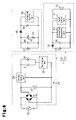
- a non-contact charger according to one embodiment of the present invention will now be discussed with reference to Figs. 1 to 3 .
- an electric toothbrush which serves as a chargeable electric system, includes a non-contact charger 11 and an electric toothbrush handle portion 12, which serves as a load device.
- the non-contact charger 11 includes a charger body 21 and an information notification block 22, which is fixed to the charger body 21.
- the charger body 21 includes a body case 23 and a primary circuit 24, which is accommodated in the body case 23.
- the body case 23 is formed from a resin and has the shape of a thin box.
- the primary circuit 24 is laid out on a substrate, which is held on a planar inner surface of the body case 23.
- the interior of the body case 23 is filled with a potting resin serving as a water resistant structure.
- the primary circuit 24 includes a bridge rectification circuit 26, which is formed by four diodes and connected to an external AC power supply 25, and a smoothing capacitor 27, which smoothes the output of the bridge rectification circuit 26.
- the primary circuit 24 further includes a voltage control unit 28 and an oscillation unit 29.
- the voltage control unit 28 controls DC output voltage at a predetermined constant voltage value (e.g., 100 V) irrelevant of the value of the voltage from the bridge rectification circuit 26 (voltage value of the external AC power supply 25).
- the oscillation unit 29 converts the output voltage from the voltage control unit 28 to a high-frequency voltage having a predetermined frequency (e.g., 50 kHz).
- the primary circuit 24 also includes a primary coil (a first induction coil) 30 and a resonance capacitor 31 The primary coil 30 generates magnetic field lines with the high-frequency voltage.
- the resonance capacitor 31 is connected in parallel to the primary coil 30.
- the information notification block 22 includes an information notification case 32 (refer to Fig. 2 ), which is formed from a resin, an auxiliary coil 33 (refer to Figs. 2 and 3 ), a resistor 34 (refer to Fig. 3 ), a light emitting diode 35 (refer to Figs. 2 and 3 ), and a resonance capacitor 36 (refer to Fig. 3 ).
- the auxiliary coil 33 is held in the information notification case 32.
- the light emitting diode 35 is one example of a notification element and a light emitting element.
- the information notification case 32 is formed to be arrangeable on the charger body 21 (body case 23).
- the information notification case 32 includes covers 32a and 33b, which cover at least three surfaces of the charger body 21 (the body case 23) facing different directions.
- the covers 32a and 32b cover the front and the two sides of the charger body 21 (the body case 23).
- the information notification case 32 is formed to cover an upper surface of the charger body 21 (the body case 23) excluding a portion corresponding to the primary coil 30.
- a holder is formed in the information notification case 32 at a location corresponding to the primary coil 30. In the illustrated example, the holder is defined by the wall of a holding socket 32c, which extends vertically through the information notification case 32.
- the wall of the holding socket 32c is formed in conformance with the profile of a basal portion of the electric toothbrush handle portion 12 and cooperates with the upper surface of the body case 23 to hold the electric toothbrush handle portion 12 when inserted therein. Further, referring to Figs. 1 and 2 , the auxiliary coil 33 is arranged in the vicinity of the primary coil 30 along (outside) the wall of the holding socket 32c.
- the auxiliary coil 33 is connected via the resistor 34 to an anode side of the light emitting diode 35. Further, the auxiliary coil 33 is connected in parallel to the resonance capacitor 36. As shown in Figs. 1 and 2 , the light emitting diode 35 has a light emitting portion exposed from the front of the information notification case 32.
- the information notification block 22 is not connected to the external AC power supply 25 and there is no possibility of the user receiving an electrical shock.
- the information notification case 32 is not filled with a potting resin that serves as a water resistant structure.
- the information notification case 32 has a simple water resistant structure, which is obtained just by eliminating large openings from its outer surface.
- the electric toothbrush handle portion 12 which has an overall rod-shape, includes a secondary coil (a second induction coil) 41 (refer to Figs. 2 and 3 ), a light emitting diode 42 (refer to Figs. 2 and 3 ), a resistor 43 (refer to Fig. 3 ), a resonance capacitor 44 (refer to Fig. 3 ), a rectification diode 45, and a rechargeable battery 46 (refer to Fig. 3 ).
- the secondary coil 41 is arranged in the basal portion of the electric toothbrush handle portion 12 in correspondence with the primary coil 30.
- the secondary coil 41 is connected via the resistor 43 to the anode side of the light emitting diode 42. Further, the secondary coil 41 is connected in parallel to the resonance capacitor 44 and connected via the rectification diode 45 to the rechargeable battery 46.
- the rechargeable battery 46 is connected to a drive circuit (not shown). When a switch (not shown) arranged on the electric toothbrush handle portion 12 is operated, drive voltage is supplied to a motor (not shown), which drives a toothbrush portion 47 (refer to Figs. 1 and 2 ).
- the primary circuit 24, which includes the primary coil 30, may be referred to as a charger body electrical circuit.
- the electrical circuit accommodated in the electric toothbrush handle portion 12 and including the secondary coil 41 and the rechargeable battery 46, which are connected to each other by a conductor, may be referred to as a load device electrical circuit.
- the electrical circuit accommodated in the information notification block 22 and including the auxiliary coil 33 and the notification element (light emitting diode 35), which are connected to each other by a conductor, may be referred to as an information notification block electrical circuit.
- the information notification block electrical circuit is not connected by a power transmission conductor to both of the charger body electrical circuit and the load device electrical circuit.
- the external AC power supply 25 is connected to the charger body 21 via a power cable but the information notification block 22 does not have a contact or a power cable electrically connectable to the external AC power supply 25 ( Figs. 2 and 3 ).
- the information notification block 22 is incapable of direct connection to the external AC power supply 25.
- the information notification block 22 includes the light emitting diode 35, which notifies the user of information indicating the activation state of the charger body 21.
- the notification element may be changed to another element that notifies the user of information related to the charger body 21 or the load device (electric toothbrush handle portion 12).
- the power transmitted in a non-contact manner through electromagnetic induction between the primary coil 30 and the auxiliary coil 33 is used as a power supply for the notification element to provide notification of information.
- an information notification block 51 in an information notification block 51, a rectification diode 52 is connected to one terminal of the auxiliary coil 33. Further, an information management unit 53 is arranged in lieu of the light emitting diode 35 and the resistor 34. The information management unit 53 is connected to a display 54, such as a liquid crystal display that serves as the notification element and shows various types of information. In this example (refer to Fig. 4 ), an information control unit 55 is connected to the rechargeable battery 46 of the electric toothbrush handle portion 12. The information control unit 55 and the information management unit 53 of the information notification block 51 are capable of communicating information through a contact or non-contact structure.
- the display 54 Based on the information obtained from the information control unit 55, the display 54 shows information indicating the state of charge of the rechargeable battery 46 (information indicating whether or not charging has been completed) or information indicating the usage time (replacement timing based on the usage time of consumable components, such as the toothbrush portion 47 of the electric toothbrush). Obviously, information indicating the activation state of the charger body 21 may also be simultaneously shown on the display 54.
- the example of Fig. 4 also arranges the notification element (display 54) in the information notification block 51 and not in the charger body 21. Thus, the information notification case does not accommodate potting resin together with the notification element.
- an information notification block 63 may replace the display 54 of the above modification (refer to Fig 4 ) with a vibration control unit 61 and a vibration generation motor 62, which is connected to the vibration control unit 61 and serves as the notification element.
- the state of charge of the rechargeable battery 46 information indicating whether or not charging has been completed
- information indicating the usage time replacement timing based on the usage time of consumable components, such as the toothbrush portion 47 of the electric toothbrush
- an information notification block 73 may replace the display 54 of the above modification (refer to Fig 4 ) with a sound control unit 71 and a speaker 72, which is connected to the sound control unit 71 and serves as the notification element.
- the state of charge of the rechargeable battery 46 information indicating whether or not charging has been completed
- information indicating the usage time replacement timing based on the usage time of consumable components, such as the toothbrush portion 47 of the electric toothbrush
- the potting resin When using the vibration generation motor or speaker in the charger body 21, the potting resin must be filled in the charger body 21 so as not to interfere with vibration or sound.
- the notification elements (motor 62 and speaker 72) are arranged in the information notification blocks 63 and 73 and not in the charger body 21.
- the information notification case does not accommodate potting resin together with the notification element.
- the information notification block 22 includes the covers 32a and 32b, which cover at least three surfaces of the charger body 21 (the body case 23) facing different directions, which are the front and the two sides of the charger body 21.
- the present invention is not limited in such a manner.
- an information notification block 81 does not include the covers 32a and 32b.
- the information notification block 22 may be, for example, snap-fitted to the charger body 21 (body case 23) and detachably attached.
- the user may easily change the design (color or shape) of the information notification block 22.
- the notification element light emitting diode 35
- replacement of only the information notification block 22 is facilitated.
- potting resin is filled into the charger body 21 so that the body case 23 is water resistant.
- a welded structure may be used to obtain the water resistance.
- the charger body 21 does not necessarily have to be water resistant.
- the information notification block 22 (information notification case 32) includes the holding socket 32c to hold the electric toothbrush handle portion 12.
- the present invention is not limited in such a manner, and a structure for holding the electric toothbrush handle portion 12 may be arranged in only the charger body 21 (body case 23), such as a cylindrical portion formed in the upper surface of the charger body 21.
- the chargeable electric system is not limited to the electric toothbrush of which the load device is the electric toothbrush handle portion 12.
- the chargeable electric device may be an electric razor of which an electric razor handle portion serves as the load device that transmits power from a non-contact charger in a non-contact manner.
Landscapes
- Engineering & Computer Science (AREA)
- Power Engineering (AREA)
- Computer Networks & Wireless Communication (AREA)
- Charge And Discharge Circuits For Batteries Or The Like (AREA)
- Brushes (AREA)
- Secondary Cells (AREA)
Applications Claiming Priority (1)
| Application Number | Priority Date | Filing Date | Title |
|---|---|---|---|
| JP2009150997A JP2011010444A (ja) | 2009-06-25 | 2009-06-25 | 非接触充電器 |
Publications (2)
| Publication Number | Publication Date |
|---|---|
| EP2267864A2 true EP2267864A2 (de) | 2010-12-29 |
| EP2267864A3 EP2267864A3 (de) | 2014-07-02 |
Family
ID=42953771
Family Applications (1)
| Application Number | Title | Priority Date | Filing Date |
|---|---|---|---|
| EP10006474.0A Withdrawn EP2267864A3 (de) | 2009-06-25 | 2010-06-22 | Kontaktlose Ladevorrichtung mit Anzeigeelement |
Country Status (3)
| Country | Link |
|---|---|
| US (1) | US20100327803A1 (de) |
| EP (1) | EP2267864A3 (de) |
| JP (1) | JP2011010444A (de) |
Cited By (20)
| Publication number | Priority date | Publication date | Assignee | Title |
|---|---|---|---|---|
| EP2801498A1 (de) | 2013-05-07 | 2014-11-12 | Brusa Elektronik AG | Anordnung und Verfahren zum induktiven Laden von mobilen Geräten |
| EP3072210A4 (de) * | 2013-11-11 | 2017-08-16 | Thoratec Corporation | Resonante stromübertragungssysteme mit kommunikation |
| US9997928B2 (en) | 2012-07-27 | 2018-06-12 | Tc1 Llc | Self-tuning resonant power transfer systems |
| US10148126B2 (en) | 2015-08-31 | 2018-12-04 | Tc1 Llc | Wireless energy transfer system and wearables |
| US10177604B2 (en) | 2015-10-07 | 2019-01-08 | Tc1 Llc | Resonant power transfer systems having efficiency optimization based on receiver impedance |
| US10186760B2 (en) | 2014-09-22 | 2019-01-22 | Tc1 Llc | Antenna designs for communication between a wirelessly powered implant to an external device outside the body |
| US10218193B2 (en) | 2014-07-29 | 2019-02-26 | Nicoventures Holdings Limited | E-cigarette and re-charging pack |
| US10251987B2 (en) | 2012-07-27 | 2019-04-09 | Tc1 Llc | Resonant power transmission coils and systems |
| US10265450B2 (en) | 2014-10-06 | 2019-04-23 | Tc1 Llc | Multiaxial connector for implantable devices |
| US10291067B2 (en) | 2012-07-27 | 2019-05-14 | Tc1 Llc | Computer modeling for resonant power transfer systems |
| US10373756B2 (en) | 2013-03-15 | 2019-08-06 | Tc1 Llc | Malleable TETs coil with improved anatomical fit |
| US10383990B2 (en) | 2012-07-27 | 2019-08-20 | Tc1 Llc | Variable capacitor for resonant power transfer systems |
| US10434235B2 (en) | 2012-07-27 | 2019-10-08 | Tci Llc | Thermal management for implantable wireless power transfer systems |
| US10525181B2 (en) | 2012-07-27 | 2020-01-07 | Tc1 Llc | Resonant power transfer system and method of estimating system state |
| US10610692B2 (en) | 2014-03-06 | 2020-04-07 | Tc1 Llc | Electrical connectors for implantable devices |
| US10695476B2 (en) | 2013-11-11 | 2020-06-30 | Tc1 Llc | Resonant power transfer systems with communications |
| US10770923B2 (en) | 2018-01-04 | 2020-09-08 | Tc1 Llc | Systems and methods for elastic wireless power transmission devices |
| CN111725863A (zh) * | 2020-05-29 | 2020-09-29 | 汤聿修 | 一种酒店电动牙刷充电设备 |
| US10898292B2 (en) | 2016-09-21 | 2021-01-26 | Tc1 Llc | Systems and methods for locating implanted wireless power transmission devices |
| US11197990B2 (en) | 2017-01-18 | 2021-12-14 | Tc1 Llc | Systems and methods for transcutaneous power transfer using microneedles |
Families Citing this family (17)
| Publication number | Priority date | Publication date | Assignee | Title |
|---|---|---|---|---|
| JP2013027074A (ja) * | 2011-07-15 | 2013-02-04 | Panasonic Corp | 非接触給電装置 |
| US20130127405A1 (en) * | 2011-11-17 | 2013-05-23 | Helmut Scherer | Wireless charging system and apparatus, and control method thereof |
| DE102011086826A1 (de) * | 2011-11-22 | 2013-05-23 | Robert Bosch Gmbh | System mit einem Handwerkzeugakku und zumindest einer Handwerkzeugakkuladevorrichtung |
| JP6071638B2 (ja) * | 2012-02-28 | 2017-02-01 | 日立マクセル株式会社 | 非接触充電装置を備える小形電気機器、および非接触式の充電システム |
| JP2014068987A (ja) * | 2012-10-01 | 2014-04-21 | Olympus Corp | 医療用無線給電システム |
| US20140196227A1 (en) * | 2013-01-17 | 2014-07-17 | Body worx USA LLC | Novel Back Brush and Soap Dispensing Device |
| WO2014132486A1 (ja) * | 2013-02-27 | 2014-09-04 | 日立マクセル株式会社 | 非接触充電装置を備える小形電気機器、および非接触式の充電システム |
| KR101963906B1 (ko) * | 2013-03-19 | 2019-03-29 | 지이 하이브리드 테크놀로지스, 엘엘씨 | 무선 전력 전송 시스템, 이에 이용되는 무선 충전 기능을 구비한 가구 및 무선 전력 전송 장치 |
| US9314096B1 (en) * | 2013-04-03 | 2016-04-19 | Michelle L. Holmes | Rechargeable toothpaste-dispensing toothbrush assembly |
| JP6291860B2 (ja) | 2014-01-21 | 2018-03-14 | 株式会社Ihi | 非接触給電システム及び磁束回収装置 |
| CN106300588A (zh) * | 2015-05-29 | 2017-01-04 | 富泰华工业(深圳)有限公司 | 辅助装置 |
| US20170105825A1 (en) * | 2015-10-16 | 2017-04-20 | Colgate-Palmolive Company | Case for powered oral care implement and system incorporating the same |
| DE102016201789A1 (de) | 2016-02-05 | 2017-08-10 | Robert Bosch Gmbh | Aufnahmeeinheit und Verfahren zum Aufnehmen von zumindest einer elektronischen Medikamentenabgabevorrichtung und/oder einem elektronischen Vitalparametermessgerät |
| WO2017145266A1 (ja) * | 2016-02-23 | 2017-08-31 | Tdk株式会社 | 非接触給電装置及び非接触電力伝送装置 |
| USD803153S1 (en) * | 2016-03-09 | 2017-11-21 | Noksibcho Aloe Co., Ltd. | Charger for electric toothbrush |
| WO2018171897A1 (en) * | 2017-03-24 | 2018-09-27 | Epcos Schweiz Gmbh | Power supply system for wireless power transfer |
| JP6467657B2 (ja) * | 2017-05-29 | 2019-02-13 | 株式会社ミック | 歯磨き支援システム、歯磨き支援方法、歯磨き支援装置、及び、歯磨き支援プログラム |
Citations (1)
| Publication number | Priority date | Publication date | Assignee | Title |
|---|---|---|---|---|
| JPH09298847A (ja) | 1996-04-30 | 1997-11-18 | Sony Corp | 非接触充電器 |
Family Cites Families (8)
| Publication number | Priority date | Publication date | Assignee | Title |
|---|---|---|---|---|
| JPH0819189A (ja) * | 1994-07-01 | 1996-01-19 | Sanyo Electric Co Ltd | 充電表示装置及び充電装置 |
| DE29618742U1 (de) * | 1996-10-28 | 1997-01-16 | Rowenta-Werke GmbH, 63071 Offenbach | Kombination einer wiederaufladbaren elektrischen Zahnbürste mit einem Spülbecher |
| FR2772208B1 (fr) * | 1997-12-05 | 2000-02-25 | Sgs Thomson Microelectronics | Dispositif d'alimentation d'une charge non lineaire, notamment un magnetron d'un four a micro-ondes |
| JP2005143181A (ja) * | 2003-11-05 | 2005-06-02 | Seiko Epson Corp | 非接触電力伝送装置 |
| US20070072474A1 (en) * | 2005-04-27 | 2007-03-29 | Nigel Beasley | Flexible power adapter systems and methods |
| KR100736053B1 (ko) * | 2005-10-24 | 2007-07-06 | 삼성전자주식회사 | 유도 방식에 의해 무선으로 전원을 공유하는 장치 및 방법 |
| US7793121B2 (en) * | 2007-03-01 | 2010-09-07 | Eastman Kodak Company | Charging display system |
| JP4725604B2 (ja) * | 2008-06-25 | 2011-07-13 | セイコーエプソン株式会社 | 送電制御装置、送電装置、受電制御装置、受電装置及び電子機器 |
-
2009
- 2009-06-25 JP JP2009150997A patent/JP2011010444A/ja active Pending
-
2010
- 2010-06-21 US US12/819,613 patent/US20100327803A1/en not_active Abandoned
- 2010-06-22 EP EP10006474.0A patent/EP2267864A3/de not_active Withdrawn
Patent Citations (1)
| Publication number | Priority date | Publication date | Assignee | Title |
|---|---|---|---|---|
| JPH09298847A (ja) | 1996-04-30 | 1997-11-18 | Sony Corp | 非接触充電器 |
Cited By (35)
| Publication number | Priority date | Publication date | Assignee | Title |
|---|---|---|---|---|
| US10383990B2 (en) | 2012-07-27 | 2019-08-20 | Tc1 Llc | Variable capacitor for resonant power transfer systems |
| US10251987B2 (en) | 2012-07-27 | 2019-04-09 | Tc1 Llc | Resonant power transmission coils and systems |
| US10525181B2 (en) | 2012-07-27 | 2020-01-07 | Tc1 Llc | Resonant power transfer system and method of estimating system state |
| US9997928B2 (en) | 2012-07-27 | 2018-06-12 | Tc1 Llc | Self-tuning resonant power transfer systems |
| US10434235B2 (en) | 2012-07-27 | 2019-10-08 | Tci Llc | Thermal management for implantable wireless power transfer systems |
| US10291067B2 (en) | 2012-07-27 | 2019-05-14 | Tc1 Llc | Computer modeling for resonant power transfer systems |
| US10668197B2 (en) | 2012-07-27 | 2020-06-02 | Tc1 Llc | Resonant power transmission coils and systems |
| US10636566B2 (en) | 2013-03-15 | 2020-04-28 | Tc1 Llc | Malleable TETS coil with improved anatomical fit |
| US10373756B2 (en) | 2013-03-15 | 2019-08-06 | Tc1 Llc | Malleable TETs coil with improved anatomical fit |
| WO2014181268A2 (de) | 2013-05-07 | 2014-11-13 | Brusa Elektronik Ag | Anordnung und verfahren zum induktiven laden von mobilen geräten |
| EP2801498A1 (de) | 2013-05-07 | 2014-11-12 | Brusa Elektronik AG | Anordnung und Verfahren zum induktiven Laden von mobilen Geräten |
| US10695476B2 (en) | 2013-11-11 | 2020-06-30 | Tc1 Llc | Resonant power transfer systems with communications |
| US10873220B2 (en) | 2013-11-11 | 2020-12-22 | Tc1 Llc | Resonant power transfer systems with communications |
| US11179559B2 (en) | 2013-11-11 | 2021-11-23 | Tc1 Llc | Resonant power transfer systems with communications |
| EP3072210A4 (de) * | 2013-11-11 | 2017-08-16 | Thoratec Corporation | Resonante stromübertragungssysteme mit kommunikation |
| US10615642B2 (en) | 2013-11-11 | 2020-04-07 | Tc1 Llc | Resonant power transfer systems with communications |
| US10610692B2 (en) | 2014-03-06 | 2020-04-07 | Tc1 Llc | Electrical connectors for implantable devices |
| US10873196B2 (en) | 2014-07-29 | 2020-12-22 | Nicoventures Holdings Limited | E-cigarette and re-charging pack |
| US10218193B2 (en) | 2014-07-29 | 2019-02-26 | Nicoventures Holdings Limited | E-cigarette and re-charging pack |
| US12095052B2 (en) | 2014-07-29 | 2024-09-17 | Nicoventures Trading Limited | E-cigarette and re-charging pack |
| US11811027B2 (en) | 2014-07-29 | 2023-11-07 | Nicoventures Trading Limited | E-cigarette and re-charging pack |
| US10536013B2 (en) | 2014-07-29 | 2020-01-14 | Nicoventures Holdings Limited | E-cigarette and re-charging pack |
| US10186760B2 (en) | 2014-09-22 | 2019-01-22 | Tc1 Llc | Antenna designs for communication between a wirelessly powered implant to an external device outside the body |
| US11245181B2 (en) | 2014-09-22 | 2022-02-08 | Tc1 Llc | Antenna designs for communication between a wirelessly powered implant to an external device outside the body |
| US10265450B2 (en) | 2014-10-06 | 2019-04-23 | Tc1 Llc | Multiaxial connector for implantable devices |
| US10148126B2 (en) | 2015-08-31 | 2018-12-04 | Tc1 Llc | Wireless energy transfer system and wearables |
| US10770919B2 (en) | 2015-08-31 | 2020-09-08 | Tc1 Llc | Wireless energy transfer system and wearables |
| US10177604B2 (en) | 2015-10-07 | 2019-01-08 | Tc1 Llc | Resonant power transfer systems having efficiency optimization based on receiver impedance |
| US10804744B2 (en) | 2015-10-07 | 2020-10-13 | Tc1 Llc | Resonant power transfer systems having efficiency optimization based on receiver impedance |
| US10898292B2 (en) | 2016-09-21 | 2021-01-26 | Tc1 Llc | Systems and methods for locating implanted wireless power transmission devices |
| US11317988B2 (en) | 2016-09-21 | 2022-05-03 | Tc1 Llc | Systems and methods for locating implanted wireless power transmission devices |
| US11197990B2 (en) | 2017-01-18 | 2021-12-14 | Tc1 Llc | Systems and methods for transcutaneous power transfer using microneedles |
| US10770923B2 (en) | 2018-01-04 | 2020-09-08 | Tc1 Llc | Systems and methods for elastic wireless power transmission devices |
| CN111725863B (zh) * | 2020-05-29 | 2021-09-28 | 汤聿修 | 一种酒店电动牙刷充电设备 |
| CN111725863A (zh) * | 2020-05-29 | 2020-09-29 | 汤聿修 | 一种酒店电动牙刷充电设备 |
Also Published As
| Publication number | Publication date |
|---|---|
| US20100327803A1 (en) | 2010-12-30 |
| EP2267864A3 (de) | 2014-07-02 |
| JP2011010444A (ja) | 2011-01-13 |
Similar Documents
| Publication | Publication Date | Title |
|---|---|---|
| EP2267864A2 (de) | Kontaktlose Ladevorrichtung mit Anzeigeelement | |
| US8810196B2 (en) | Inductive charger and charging method | |
| JP5362568B2 (ja) | 電磁気エネルギ転送のための装置、システム及び方法 | |
| EP1763120A2 (de) | Berührungsloser Batterielader | |
| WO2015050073A1 (ja) | 補聴器及び補聴器充電システム | |
| EP3282559B1 (de) | Vorrichtung zur kontaktfreien stromübertragung | |
| EP3282558B1 (de) | Stromübertragungsvorrichtung für vorrichtung zur kontaktlosen stromversorgung | |
| JP6604708B2 (ja) | 補聴器 | |
| KR101976214B1 (ko) | 무선 충전 기능을 구비한 무선 마이크 및 이를 충전하기 위한 무선 전력 전송 장치 | |
| US8351302B2 (en) | Power supply for clock | |
| JP2012070566A (ja) | 非接触充電式の電気機器およびその充電システム | |
| HK1147603A (en) | Non-contact charger with an indicator | |
| JP2011160535A (ja) | 電子機器 | |
| KR20150049784A (ko) | 음향알림부재를 포함하는 충전기 | |
| KR100301430B1 (ko) | 배터리및그를충전하기위한배터리충전시스템 | |
| CN209282885U (zh) | 充电装置 | |
| US20090195078A1 (en) | Inductive electric power structure and system | |
| KR20120008628A (ko) | 피씨비 일체형 무접점 배터리 장치 및 충전 시스템 | |
| JP2014099954A (ja) | 非接触アダプタ及び受電用カセット | |
| JP2013070544A (ja) | 非接触電力伝送電源アダプター | |
| JPH04131144U (ja) | 充電装置 |
Legal Events
| Date | Code | Title | Description |
|---|---|---|---|
| PUAI | Public reference made under article 153(3) epc to a published international application that has entered the european phase |
Free format text: ORIGINAL CODE: 0009012 |
|
| 17P | Request for examination filed |
Effective date: 20100707 |
|
| AK | Designated contracting states |
Kind code of ref document: A2 Designated state(s): AL AT BE BG CH CY CZ DE DK EE ES FI FR GB GR HR HU IE IS IT LI LT LU LV MC MK MT NL NO PL PT RO SE SI SK SM TR |
|
| AX | Request for extension of the european patent |
Extension state: BA ME RS |
|
| REG | Reference to a national code |
Ref country code: HK Ref legal event code: DE Ref document number: 1147603 Country of ref document: HK |
|
| RAP1 | Party data changed (applicant data changed or rights of an application transferred) |
Owner name: PANASONIC CORPORATION |
|
| PUAL | Search report despatched |
Free format text: ORIGINAL CODE: 0009013 |
|
| STAA | Information on the status of an ep patent application or granted ep patent |
Free format text: STATUS: THE APPLICATION HAS BEEN WITHDRAWN |
|
| AK | Designated contracting states |
Kind code of ref document: A3 Designated state(s): AL AT BE BG CH CY CZ DE DK EE ES FI FR GB GR HR HU IE IS IT LI LT LU LV MC MK MT NL NO PL PT RO SE SI SK SM TR |
|
| AX | Request for extension of the european patent |
Extension state: BA ME RS |
|
| RIC1 | Information provided on ipc code assigned before grant |
Ipc: H02J 7/00 20060101ALI20140523BHEP Ipc: H02J 7/02 20060101AFI20140523BHEP |
|
| 18W | Application withdrawn |
Effective date: 20140604 |
|
| REG | Reference to a national code |
Ref country code: HK Ref legal event code: WD Ref document number: 1147603 Country of ref document: HK |