EP2268121A1 - Dispositif de montage de composants électroniques - Google Patents
Dispositif de montage de composants électroniques Download PDFInfo
- Publication number
- EP2268121A1 EP2268121A1 EP10010899A EP10010899A EP2268121A1 EP 2268121 A1 EP2268121 A1 EP 2268121A1 EP 10010899 A EP10010899 A EP 10010899A EP 10010899 A EP10010899 A EP 10010899A EP 2268121 A1 EP2268121 A1 EP 2268121A1
- Authority
- EP
- European Patent Office
- Prior art keywords
- suction nozzle
- electronic component
- nozzle
- vertical movement
- time
- Prior art date
- Legal status (The legal status is an assumption and is not a legal conclusion. Google has not performed a legal analysis and makes no representation as to the accuracy of the status listed.)
- Withdrawn
Links
Images






Classifications
-
- H—ELECTRICITY
- H05—ELECTRIC TECHNIQUES NOT OTHERWISE PROVIDED FOR
- H05K—PRINTED CIRCUITS; CASINGS OR CONSTRUCTIONAL DETAILS OF ELECTRIC APPARATUS; MANUFACTURE OF ASSEMBLAGES OF ELECTRICAL COMPONENTS
- H05K13/00—Apparatus or processes specially adapted for manufacturing or adjusting assemblages of electric components
- H05K13/08—Monitoring manufacture of assemblages
-
- H—ELECTRICITY
- H05—ELECTRIC TECHNIQUES NOT OTHERWISE PROVIDED FOR
- H05K—PRINTED CIRCUITS; CASINGS OR CONSTRUCTIONAL DETAILS OF ELECTRIC APPARATUS; MANUFACTURE OF ASSEMBLAGES OF ELECTRICAL COMPONENTS
- H05K13/00—Apparatus or processes specially adapted for manufacturing or adjusting assemblages of electric components
- H05K13/02—Feeding of components
-
- H—ELECTRICITY
- H05—ELECTRIC TECHNIQUES NOT OTHERWISE PROVIDED FOR
- H05K—PRINTED CIRCUITS; CASINGS OR CONSTRUCTIONAL DETAILS OF ELECTRIC APPARATUS; MANUFACTURE OF ASSEMBLAGES OF ELECTRICAL COMPONENTS
- H05K13/00—Apparatus or processes specially adapted for manufacturing or adjusting assemblages of electric components
- H05K13/04—Mounting of components, e.g. of leadless components
- H05K13/0404—Pick-and-place heads or apparatus, e.g. with jaws
- H05K13/0408—Incorporating a pick-up tool
- H05K13/041—Incorporating a pick-up tool having multiple pick-up tools
-
- H—ELECTRICITY
- H05—ELECTRIC TECHNIQUES NOT OTHERWISE PROVIDED FOR
- H05K—PRINTED CIRCUITS; CASINGS OR CONSTRUCTIONAL DETAILS OF ELECTRIC APPARATUS; MANUFACTURE OF ASSEMBLAGES OF ELECTRICAL COMPONENTS
- H05K13/00—Apparatus or processes specially adapted for manufacturing or adjusting assemblages of electric components
- H05K13/04—Mounting of components, e.g. of leadless components
- H05K13/0404—Pick-and-place heads or apparatus, e.g. with jaws
- H05K13/0413—Pick-and-place heads or apparatus, e.g. with jaws with orientation of the component while holding it; Drive mechanisms for gripping tools, e.g. lifting, lowering or turning of gripping tools
-
- Y—GENERAL TAGGING OF NEW TECHNOLOGICAL DEVELOPMENTS; GENERAL TAGGING OF CROSS-SECTIONAL TECHNOLOGIES SPANNING OVER SEVERAL SECTIONS OF THE IPC; TECHNICAL SUBJECTS COVERED BY FORMER USPC CROSS-REFERENCE ART COLLECTIONS [XRACs] AND DIGESTS
- Y10—TECHNICAL SUBJECTS COVERED BY FORMER USPC
- Y10T—TECHNICAL SUBJECTS COVERED BY FORMER US CLASSIFICATION
- Y10T29/00—Metal working
- Y10T29/53—Means to assemble or disassemble
- Y10T29/5313—Means to assemble electrical device
- Y10T29/53174—Means to fasten electrical component to wiring board, base, or substrate
-
- Y—GENERAL TAGGING OF NEW TECHNOLOGICAL DEVELOPMENTS; GENERAL TAGGING OF CROSS-SECTIONAL TECHNOLOGIES SPANNING OVER SEVERAL SECTIONS OF THE IPC; TECHNICAL SUBJECTS COVERED BY FORMER USPC CROSS-REFERENCE ART COLLECTIONS [XRACs] AND DIGESTS
- Y10—TECHNICAL SUBJECTS COVERED BY FORMER USPC
- Y10T—TECHNICAL SUBJECTS COVERED BY FORMER US CLASSIFICATION
- Y10T29/00—Metal working
- Y10T29/53—Means to assemble or disassemble
- Y10T29/5313—Means to assemble electrical device
- Y10T29/53191—Means to apply vacuum directly to position or hold work part
Definitions
- the invention provides an electronic component mounting apparatus including: a component feeding unit supplying an electronic component; a suction nozzle picking the electronic component supplied from the component feeding unit by suction; a horizontal axis moving the suction nozzle in a horizontal direction; a vertical movement mechanism vertically moving the suction nozzle; and a control device starting the horizontal axis based on a rising speed of the suction nozzle and start delay time of the horizontal axis after the electronic component is picked by suction by the suction nozzle or after the electronic component picked by suction by the suction nozzle is mounted on a printed board.
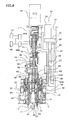
- a numeral 62 designates a nozzle support member fixed to a lower portion of the first cylinder 57 and rotates by ⁇ with the first cylinder 57.
- a vertical movement support piece 63 is formed on a lower end of this nozzle support member 62, horizontally lying in a circumference direction. This vertical movement support piece 63 vertically moves together with vertical movement of the first cylinder 57. The lowering of the vertical movement support piece 63 makes a predetermined suction nozzle 15 among a plurality of nozzles lower.
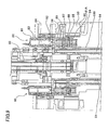
- the solenoid valve 82 has a circular electromagnet 83 provided on an inner surface of the case 81, a path switch body 85 provided with a cylindrical permanent magnet 84 corresponding to the electromagnet 83 in its upper portion and vertically moving inside the case 81 according to electrical conduction and electrical non-conduction through the electromagnet 83, and so on.
- An air blow path 86, a nozzle connection path 87, and a vacuum leading path 88 are formed between the path switch body 85 and a cylinder portion 81A in the lower portion of the case 81 in due order from upper to lower sides.
- the nozzle axis 64 has a nozzle axis path 100 connected with an inner path of the nozzle 15 and the nozzle connection path 87.
- a numeral 49A designates a switch valve connected with the air switch valve 80 in one end, which switches its connection with the vacuum source 47 and the air supply source 48 so as to make the suction nozzle 15 suck and blow respectively.
- a numeral 49B designates an open-close valve connected with the air switch valve 80 in one end and with the air supply source 48 in another end. This is a valve used for mounting an electronic component by the suction nozzle 15 by establishing a state of blowing air from the air supply source 48 by its opening before the air switch valve 80 switches from air suction to air blow and then breaking vacuum when the air switch valve 80 switches to the air blow as the suction nozzle 15 picking the electronic component starts lowering.
- the CPU 90 determines the lowering start position of the suction nozzle 15 during its movement, based on the start delay time of the nozzle vertical movement motor 51 for vertically moving the suction nozzle 15, that is, the time (NL axis start delay) tZ from the time when the CPU 90 outputs an operation signal for the nozzle vertical movement motor 51 until the time when the nozzle vertical movement motor 51 actually starts operating, which is stored in the RAM 92, and the time tnl from the time when the suction nozzle 15 starts lowering until the time when the suction nozzle 15 reaches the distance L3 at its lowering speed (set for each of the types of the electronic components and stored as the component library data in the RAM 92 in advance), and then the CPU 90 outputs an operation signal for the nozzle vertical movement motor 51 as early as possible. This realizes the earlier timing to start the lowering of the suction nozzle 15 during the movement of the mounting head 16, that is, during the movement of the su
- the CPU 90 determines the lowering start position of the suction nozzle 15 during its movement based on the time (NL axis start delay) tZ from the time when the CPU 90 outputs an operation signal for the nozzle vertical movement motor 51 until the time when the nozzle vertical movement motor 51 actually starts operating, and the time tnl from the time when the suction nozzle 15 starts lowering until the time when the suction nozzle 15 reaches the distance L3 at its lowering speed, and the CPU 90 outputs an operation signal for the nozzle vertical movement motor 51 as early as possible.
- the CPU 90 forms a state of air blow from the air supply source 48 by opening the open-close valve 49B before it switches the air switch valve 80 (the electromagnet 83 of the solenoid valve 82) corresponding to the suction nozzle 15 holding the electronic component which the line sensor unit 37 detects as being attached with wrong posture switches from the air suction side to the air blow side by electrical non-conduction. Then, the CPU 90 switches the air switch valve 80 to the air blow side when the suction nozzle 15 holding the electronic component starts lowering, and breaks the vacuum of the suction nozzle 15 by air from the air supply source 48 through the open-close valve 49B, thereby dropping the electronic component D in the collection box 79 to complete the individual discharge (collection) operation.
- the air switch valve 80 the electromagnet 83 of the solenoid valve 82
- the air from the air supply source 48 is blown in the inner path of the suction nozzle 15 through the air blow path 86, the nozzle connection path 87, and the nozzle axis path 100, and blown to the outside of the suction nozzle 15, thereby dropping the electronic component D to complete the individual discharge (collection) operation.
- air blow pressure from the suction nozzle 15 is low since the path from the open-close valve 49B to the air switch valve 80 is not closed.
- the corresponding air switch valve 80 is switched to the air blow side when the suction nozzle 15 holding the electronic component by suction starts lowering, and the vacuum suction of the suction nozzle 15 is broken by air from the air supply source 48 through the open-close valve 49B, and the electronic component is mounted on the printed board P.
Landscapes
- Engineering & Computer Science (AREA)
- Manufacturing & Machinery (AREA)
- Microelectronics & Electronic Packaging (AREA)
- Operations Research (AREA)
- Supply And Installment Of Electrical Components (AREA)
Applications Claiming Priority (2)
| Application Number | Priority Date | Filing Date | Title |
|---|---|---|---|
| JP2005287152A JP4695954B2 (ja) | 2005-09-30 | 2005-09-30 | 電子部品装着装置 |
| EP06020543A EP1771060B1 (fr) | 2005-09-30 | 2006-09-29 | Dispositif de montage de composants électroniques |
Related Parent Applications (1)
| Application Number | Title | Priority Date | Filing Date |
|---|---|---|---|
| EP06020543.2 Division | 2006-09-29 |
Publications (2)
| Publication Number | Publication Date |
|---|---|
| EP2268121A1 true EP2268121A1 (fr) | 2010-12-29 |
| EP2268121A8 EP2268121A8 (fr) | 2011-09-21 |
Family
ID=37635777
Family Applications (2)
| Application Number | Title | Priority Date | Filing Date |
|---|---|---|---|
| EP06020543A Ceased EP1771060B1 (fr) | 2005-09-30 | 2006-09-29 | Dispositif de montage de composants électroniques |
| EP10010899A Withdrawn EP2268121A1 (fr) | 2005-09-30 | 2006-09-29 | Dispositif de montage de composants électroniques |
Family Applications Before (1)
| Application Number | Title | Priority Date | Filing Date |
|---|---|---|---|
| EP06020543A Ceased EP1771060B1 (fr) | 2005-09-30 | 2006-09-29 | Dispositif de montage de composants électroniques |
Country Status (5)
| Country | Link |
|---|---|
| US (1) | US20070074387A1 (fr) |
| EP (2) | EP1771060B1 (fr) |
| JP (1) | JP4695954B2 (fr) |
| KR (1) | KR101227314B1 (fr) |
| CN (1) | CN1942093B (fr) |
Cited By (1)
| Publication number | Priority date | Publication date | Assignee | Title |
|---|---|---|---|---|
| CN112566486A (zh) * | 2020-11-27 | 2021-03-26 | 江苏高明安光电有限公司 | 一种液晶显示屏贴片机 |
Families Citing this family (15)
| Publication number | Priority date | Publication date | Assignee | Title |
|---|---|---|---|---|
| JP2007221050A (ja) * | 2006-02-20 | 2007-08-30 | Yamagata Casio Co Ltd | 作業ヘッドの移動制御方法と部品実装装置 |
| JP4764449B2 (ja) * | 2008-03-25 | 2011-09-07 | ヤマハ発動機株式会社 | 部品装着装置 |
| KR101594083B1 (ko) | 2009-08-04 | 2016-02-16 | 한화테크윈 주식회사 | 전자 부품 제조 장치 |
| JP4926236B2 (ja) * | 2009-12-28 | 2012-05-09 | 株式会社日立ハイテクインスツルメンツ | 電子部品の装着方法 |
| JP5702157B2 (ja) * | 2011-01-11 | 2015-04-15 | Juki株式会社 | 電子部品実装装置 |
| JP5927497B2 (ja) * | 2012-06-08 | 2016-06-01 | パナソニックIpマネジメント株式会社 | 部品実装装置および部品実装方法 |
| JP5927496B2 (ja) * | 2012-06-08 | 2016-06-01 | パナソニックIpマネジメント株式会社 | 部品実装装置および部品実装方法 |
| JP5877315B2 (ja) * | 2012-06-19 | 2016-03-08 | パナソニックIpマネジメント株式会社 | 部品実装装置、パーツフィーダ及び部品実装装置におけるパーツフィーダ引き抜き規制解除方法 |
| JP2014038946A (ja) * | 2012-08-16 | 2014-02-27 | Sony Corp | 実装装置、部材の配置方法及び基板の製造方法 |
| CN103152994B (zh) * | 2013-02-04 | 2017-03-01 | 广东工业大学 | 一种多吸嘴同步吸贴的高效贴片头 |
| TW201432319A (zh) * | 2013-02-05 | 2014-08-16 | Hon Hai Prec Ind Co Ltd | 光纖連接器組裝裝置 |
| DE102014003711A1 (de) * | 2013-04-05 | 2014-10-09 | Heidelberger Druckmaschinen Ag | Zylinder zum Transport von Druckbogen entlang eines UV- oder Elektronenstrahltrockners |
| CN103747666B (zh) * | 2014-01-22 | 2016-06-29 | 哈尔滨工业大学 | 全自动贴片机吸嘴头升降轴机械原点定位电气控制方法 |
| CN107052797B (zh) * | 2017-06-13 | 2023-04-11 | 昆山嘉斯特自动化技术有限公司 | 一种单向阀组装机 |
| CN117619774A (zh) * | 2022-08-09 | 2024-03-01 | 无锡奥特维科技股份有限公司 | 一种硅片收片方法 |
Citations (4)
| Publication number | Priority date | Publication date | Assignee | Title |
|---|---|---|---|---|
| US5339248A (en) * | 1992-08-27 | 1994-08-16 | Matsushita Electric Industrial Co., Ltd. | Apparatus for mounting electronic component on substrate |
| JP2001156498A (ja) | 1999-11-30 | 2001-06-08 | Yamaha Motor Co Ltd | 表面実装部品装着機における持ち帰り電子部品の検出方法 |
| EP1189497A2 (fr) * | 2000-09-18 | 2002-03-20 | Matsushita Electric Industrial Co., Ltd. | Machine et procédé pour le montage de composants sur un substrat |
| US20040168310A1 (en) * | 1999-09-03 | 2004-09-02 | Matsushita Electric Industrial Co., Ltd. | Method and apparatus for mounting components |
Family Cites Families (11)
| Publication number | Priority date | Publication date | Assignee | Title |
|---|---|---|---|---|
| JPH07109957B2 (ja) * | 1988-06-21 | 1995-11-22 | 松下電器産業株式会社 | 電子部品装着方法 |
| JP3058708B2 (ja) * | 1991-04-09 | 2000-07-04 | 松下電器産業株式会社 | 部品装着機 |
| JP3229748B2 (ja) * | 1994-05-18 | 2001-11-19 | 三洋電機株式会社 | 電子部品自動装着装置 |
| JPH08162797A (ja) * | 1994-12-08 | 1996-06-21 | Matsushita Electric Ind Co Ltd | 電子部品実装装置 |
| EP1050384A4 (fr) * | 1996-12-25 | 2000-11-08 | Matsushita Electric Industrial Co Ltd | Tete-support de piece, dispositif de montage de piece et procede de fixation de piece |
| US6374484B1 (en) * | 1997-08-29 | 2002-04-23 | Matsushita Electric Industrial Co., Ltd. | Parts mounting method and apparatus |
| JPH11251792A (ja) * | 1998-03-03 | 1999-09-17 | Matsushita Electric Ind Co Ltd | 電子部品装着機 |
| US6629007B1 (en) * | 1998-12-25 | 2003-09-30 | Matsushita Electric Industrial Co., Ltd. | Apparatus and method for notifying lack of component in advance, component mounting apparatus, and article of manufacture comprising computer usable medium |
| US6571462B1 (en) * | 1999-04-27 | 2003-06-03 | Matsushita Electric Industrial Co., Ltd | Electronic component mounting apparatus using duplicate sources of components |
| US6862803B2 (en) * | 2000-08-29 | 2005-03-08 | Matsushita Electric Industrial Co., Ltd. | Method for mounting electronic component |
| JP4109905B2 (ja) * | 2002-05-31 | 2008-07-02 | 松下電器産業株式会社 | 部品実装基板生産装置 |
-
2005
- 2005-09-30 JP JP2005287152A patent/JP4695954B2/ja not_active Expired - Fee Related
-
2006
- 2006-09-26 CN CN2006101399086A patent/CN1942093B/zh active Active
- 2006-09-28 US US11/528,695 patent/US20070074387A1/en not_active Abandoned
- 2006-09-29 KR KR1020060095452A patent/KR101227314B1/ko active Active
- 2006-09-29 EP EP06020543A patent/EP1771060B1/fr not_active Ceased
- 2006-09-29 EP EP10010899A patent/EP2268121A1/fr not_active Withdrawn
Patent Citations (4)
| Publication number | Priority date | Publication date | Assignee | Title |
|---|---|---|---|---|
| US5339248A (en) * | 1992-08-27 | 1994-08-16 | Matsushita Electric Industrial Co., Ltd. | Apparatus for mounting electronic component on substrate |
| US20040168310A1 (en) * | 1999-09-03 | 2004-09-02 | Matsushita Electric Industrial Co., Ltd. | Method and apparatus for mounting components |
| JP2001156498A (ja) | 1999-11-30 | 2001-06-08 | Yamaha Motor Co Ltd | 表面実装部品装着機における持ち帰り電子部品の検出方法 |
| EP1189497A2 (fr) * | 2000-09-18 | 2002-03-20 | Matsushita Electric Industrial Co., Ltd. | Machine et procédé pour le montage de composants sur un substrat |
Cited By (1)
| Publication number | Priority date | Publication date | Assignee | Title |
|---|---|---|---|---|
| CN112566486A (zh) * | 2020-11-27 | 2021-03-26 | 江苏高明安光电有限公司 | 一种液晶显示屏贴片机 |
Also Published As
| Publication number | Publication date |
|---|---|
| EP1771060A1 (fr) | 2007-04-04 |
| US20070074387A1 (en) | 2007-04-05 |
| JP2007096238A (ja) | 2007-04-12 |
| KR101227314B1 (ko) | 2013-01-28 |
| EP1771060B1 (fr) | 2012-11-21 |
| EP2268121A8 (fr) | 2011-09-21 |
| JP4695954B2 (ja) | 2011-06-08 |
| CN1942093B (zh) | 2011-11-16 |
| KR20070037382A (ko) | 2007-04-04 |
| CN1942093A (zh) | 2007-04-04 |
Similar Documents
| Publication | Publication Date | Title |
|---|---|---|
| EP1771060B1 (fr) | Dispositif de montage de composants électroniques | |
| EP1521515B1 (fr) | Dispositif de montage de composants électriques | |
| US8186047B2 (en) | Method of mounting electronic component | |
| US7246429B2 (en) | Electronic component mounting apparatus | |
| US7159305B2 (en) | Electronic component mounting apparatus | |
| US7581310B2 (en) | Electronic component mounting apparatus | |
| EP1781078B1 (fr) | Appareil pour monter des composants électroniques | |
| EP1814375B1 (fr) | Appareil de montage de composant électronique | |
| JP4713353B2 (ja) | 電子部品装着装置 | |
| JP2007036163A (ja) | 電子部品装着装置 |
Legal Events
| Date | Code | Title | Description |
|---|---|---|---|
| PUAI | Public reference made under article 153(3) epc to a published international application that has entered the european phase |
Free format text: ORIGINAL CODE: 0009012 |
|
| AC | Divisional application: reference to earlier application |
Ref document number: 1771060 Country of ref document: EP Kind code of ref document: P |
|
| AK | Designated contracting states |
Kind code of ref document: A1 Designated state(s): DE NL |
|
| RIN1 | Information on inventor provided before grant (corrected) |
Inventor name: FUKUSHIMA, YOSHIHARU Inventor name: KAMEDA, MAKIO Inventor name: IEIZUMI, KAZUYOSHI Inventor name: KASHITANI, HISAYOSHI |
|
| 17P | Request for examination filed |
Effective date: 20110629 |
|
| STAA | Information on the status of an ep patent application or granted ep patent |
Free format text: STATUS: THE APPLICATION IS DEEMED TO BE WITHDRAWN |
|
| 18D | Application deemed to be withdrawn |
Effective date: 20140401 |