EP2268223B1 - Lichtbasiertes gerät zur endovaskulären behandlung pathologisch veränderter blutgefässe - Google Patents
Lichtbasiertes gerät zur endovaskulären behandlung pathologisch veränderter blutgefässe Download PDFInfo
- Publication number
- EP2268223B1 EP2268223B1 EP09734317.2A EP09734317A EP2268223B1 EP 2268223 B1 EP2268223 B1 EP 2268223B1 EP 09734317 A EP09734317 A EP 09734317A EP 2268223 B1 EP2268223 B1 EP 2268223B1
- Authority
- EP
- European Patent Office
- Prior art keywords
- light
- catheter
- vessel
- applicator
- light applicator
- Prior art date
- Legal status (The legal status is an assumption and is not a legal conclusion. Google has not performed a legal analysis and makes no representation as to the accuracy of the status listed.)
- Active
Links
Images


Classifications
-
- A—HUMAN NECESSITIES
- A61—MEDICAL OR VETERINARY SCIENCE; HYGIENE
- A61B—DIAGNOSIS; SURGERY; IDENTIFICATION
- A61B18/00—Surgical instruments, devices or methods for transferring non-mechanical forms of energy to or from the body
- A61B18/18—Surgical instruments, devices or methods for transferring non-mechanical forms of energy to or from the body by applying electromagnetic radiation, e.g. microwaves
- A61B18/20—Surgical instruments, devices or methods for transferring non-mechanical forms of energy to or from the body by applying electromagnetic radiation, e.g. microwaves using laser
- A61B18/22—Surgical instruments, devices or methods for transferring non-mechanical forms of energy to or from the body by applying electromagnetic radiation, e.g. microwaves using laser the beam being directed along or through a flexible conduit, e.g. an optical fibre; Couplings or hand-pieces therefor
- A61B18/24—Surgical instruments, devices or methods for transferring non-mechanical forms of energy to or from the body by applying electromagnetic radiation, e.g. microwaves using laser the beam being directed along or through a flexible conduit, e.g. an optical fibre; Couplings or hand-pieces therefor with a catheter
-
- A—HUMAN NECESSITIES
- A61—MEDICAL OR VETERINARY SCIENCE; HYGIENE
- A61B—DIAGNOSIS; SURGERY; IDENTIFICATION
- A61B18/00—Surgical instruments, devices or methods for transferring non-mechanical forms of energy to or from the body
- A61B18/18—Surgical instruments, devices or methods for transferring non-mechanical forms of energy to or from the body by applying electromagnetic radiation, e.g. microwaves
- A61B18/20—Surgical instruments, devices or methods for transferring non-mechanical forms of energy to or from the body by applying electromagnetic radiation, e.g. microwaves using laser
- A61B2018/2035—Beam shaping or redirecting; Optical components therefor
- A61B2018/20361—Beam shaping or redirecting; Optical components therefor with redirecting based on sensed condition, e.g. tissue analysis or tissue movement
-
- A—HUMAN NECESSITIES
- A61—MEDICAL OR VETERINARY SCIENCE; HYGIENE
- A61B—DIAGNOSIS; SURGERY; IDENTIFICATION
- A61B18/00—Surgical instruments, devices or methods for transferring non-mechanical forms of energy to or from the body
- A61B18/18—Surgical instruments, devices or methods for transferring non-mechanical forms of energy to or from the body by applying electromagnetic radiation, e.g. microwaves
- A61B18/20—Surgical instruments, devices or methods for transferring non-mechanical forms of energy to or from the body by applying electromagnetic radiation, e.g. microwaves using laser
- A61B18/22—Surgical instruments, devices or methods for transferring non-mechanical forms of energy to or from the body by applying electromagnetic radiation, e.g. microwaves using laser the beam being directed along or through a flexible conduit, e.g. an optical fibre; Couplings or hand-pieces therefor
- A61B2018/2255—Optical elements at the distal end of probe tips
- A61B2018/2261—Optical elements at the distal end of probe tips with scattering, diffusion or dispersion of light
-
- A—HUMAN NECESSITIES
- A61—MEDICAL OR VETERINARY SCIENCE; HYGIENE
- A61B—DIAGNOSIS; SURGERY; IDENTIFICATION
- A61B90/00—Instruments, implements or accessories specially adapted for surgery or diagnosis and not covered by any of the groups A61B1/00 - A61B50/00, e.g. for luxation treatment or for protecting wound edges
- A61B90/36—Image-producing devices or illumination devices not otherwise provided for
- A61B90/37—Surgical systems with images on a monitor during operation
Definitions
- the following presents a new, light-based method of endovascular treatment, in particular of pathologically altered blood vessels.
- ELT Endovascular Laser Therapy
- the therapy light is absorbed by the tissue and / or blood, which causes the vein wall to heat up, leading in turn initially to a thermal necrosis of the cells in the blood vessel wall with a collagen contraction and wall thickening, usually followed by a thrombotic closure of the treated vein.
- the subsequent inflammatory reaction and repair processes lead, sometimes not before after a number of weeks, to the obliteration of the truncal vein that has been treated and thus to the hemodynamic disconnection of the treated vein segment and branch varicose veins that were supplied by this.
- the aim of endovascular therapy is inter alia to close pathologically altered blood vessels using a minimally invasive method.
- a procedure currently known and practiced to achieve this therapeutic aim is as follows: After puncturing the vessel to be treated, a simple fiberglass or complex-structure energy applicator or light applicator is positioned intravenously usually via a type of catheter system using a sort of Seldinger technique and therapeutic light is applied in this way. Before or during the treatment, however, the catheter system, which is only used for positioning, is generally pulled out of the vessel along with the light applicator, whilst emitting the laser light. It is assumed that the blood vessel closes immediately with this treatment method, especially because of the instant contraction and/or the formation of a thrombus.
- the desired vessel or cavity is punctured with a sharp hollow needle, also called access needle or trocar, optionally with ultrasound guidance if necessary.
- a round-tipped guidewire is then advanced through the lumen of the access needle, and the access needle is withdrawn.
- the catheter or "catheter sheath” is inserted along the guidewire into the cavity or vessel, optionally after enlarging the puncture channel employing a dilator.
- the guidewire is withdrawn.
- Ultrasound guidance or fluoroscopy may be used to confirm the position of the catheter and to manoeuvre it to the desired location. Injection of radiocontrast may be used to visualise organs.
- Interventional procedures such as thermoablation, angioplasty, embolisation or biopsy, may be performed.
- the sheath is withdrawn.
- a sealing device may be used to close the hole made by the procedure.
- the light emitting part of the light applicator usually a special fibre tip or especially a bare fibre tip, is always shifted through the open distal end of the catheter (catheter sheath) and is used in contact with the vessel and/or fluid within the vessel withdrawing applicator and catheter (catheter sheath) together while applying light.
- Other approaches of the prior art directly introduce the light applicator only into the vessel. This is an one step technique.
- the light applicator Upon percutaneous puncture of the vessel, the light applicator is introduced into the vessel and moved to the location of interest within the vessel, often with ultrasound guidance and while the light applicator is moved back (in direct contact with the vessel or fluid within the vessel) light energy is applied to the length of the vessel that shall be treated. A repeated moving of the light applicator to the same position is impossible. A punctual adhesion of tissue or blood on the surface of the applicator may even lead to a local overheating of the vessel or the applicator.
- WO99/12489 US 7,396,355 , US 6,752,803 and US 6,258,084 disclose an electrocatheter suitable for shrinking blood vessels upon applying energy.
- the catheter comprises working electrodes, which are - when used - expanded from the catheter and are in direct contact with the blood vessel to be treated.
- a tumescent fluid is injected into the tissue surrounding the treatment site.
- a further development of this electrocatheter is disclosed in WO 00/10475 , US 6,769,433 and US 7,406,970 .
- the electrode is put in apposition with the vessel wall and the wall is pre-shaped before applying energy to the electrodes.
- WO 2007/014063 discloses a catheter including a therapeutic element, such as a resistive heating element usable to deliver energy for ligating, or reducing the diameter of a vessel.
- US20060069417 discloses a catheter, which introduces electrodes in a vein for a minimally invasive treatment of venous insufficiency by the application of energy to cause selective heating of the vein.
- the catheter is positioned within the vein to be treated, and the electrodes on the catheter are moved toward one side of the vein.
- RF energy is applied in a directional manner from the electrodes at the working end of the catheter to cause localized heating and corresponding shrinkage of the adjacent venous tissue.
- WO00/44296 and EP 1156751 B1 disclose an endovascular laser device for treating varicose veins.
- the device of EP 1156751 B1 comprises a
- EP 1527748 discloses an endovascular laser treatment delivery device having a translucent longitudinal tube that allows visual check of aiming beam to locate an optical fiber tip during its insertion.
- this device of EP 1156751 B1 may cause unwanted damage to the interior wall of the vessel to be treated due to the exposure of the fibre optic line to the vessel wall.
- the free fibre optic line of EP 1156751 B1 may cause pain and small injuries such as perforations and hematomas.
- a blood vessel treatment device comprising: a light applicator connected to the light emitting unit, and a catheter/applicator tube for inserting the light applicator into and for guiding the light applicator within a vessel, wherein said catheter and said light applicator are arranged and adapted such that in use at any time said light applicator does not make intraluminal contact with any vessel wall and the light applicator is capable of delivering light energy through the sheath of the catheter so as to emit light energy to cause damage to a vessel wall, preferably so as to result in a subsequent decrease in the diameter of said vessel.
- This device surprisingly overcomes the problems in the art arising from applying high energy densities while contacting the light applicator directly to the vessel, such as high local temperatures, protein agglomeration or aggregation, carbonizing of organic material or unwanted destruction of healthy structures or ingredients of body fluid or the applicator itself.
- the catheter is not removed until the application of energy to the vessel has been completed (i.e. the catheter is still in place while the applicator has already been removed), the vessel - upon removal of the catheter - shrinks or collapses as intended.
- vessels may be treated safely, which encompass many bendings or vessels at bends or at constrictions may be treated, since the catheter protects the vessel from the risk of local damage arising from contact with the light applicator.
- a punctual adhesion of tissue or blood on the surface of the applicator is methodically and technically excluded, inhibiting local overheating of the vessel or the applicator.
- the catheter protects the vessel from damage. In case of break-down, the fragments of the light applicator can be easily withdrawn from the vessel, since they remain inside the catheter.
- an ultrasound or radioactive imaging unit for imaging the treated vessel and/ or a temperature or coagulation detecting unit are placed within the catheter.
- the device is preferably a sterile device. Sterilization and reuse of the applicator is comparatively easy, since the light applicator is not in contact with body fluids, tissue or the vessel to be treated.
- the device is open at the distal end and the catheter may be introduced into the vessel employing the Seldinger Technique.
- the device is closed at the distal end and the catheter may be introduced into the vessel in a one-step-process, without the need of using a wire guide. Both embodiments are described in detail below and are exemplarily shown in Figure 2 .
- the devices of these two embodiments may even be compatible with each other, i.e. the device of the present invention may such that it can be inserted employing both techniques. Accordingly, in a third embodiment - for the first time to our knowledge with the same device - a change between these two techniques even during the therapeutic intervention is possible; just the catheter has to be changed or only to be modified, e.g. cut, at the tip.
- a kit comprising one or more light applicators, e.g.
- a catheter for inserting the light applicator into and for guiding the light applicator within a vessel for different purposes or different laser units; a catheter for inserting the light applicator into and for guiding the light applicator within a vessel; a guide wire; and an access needle, wherein said catheter and said light applicator are arranged and adapted such that in use at any time said light applicator does not make intraluminal contact with any vessel wall and the light applicator is capable of delivering light energy through the sheath of the catheter so as to emit light energy to cause damage to a vessel wall, preferably so as to result in a subsequent decrease in the diameter of said vessel.
- the method of the present disclosure is represented by two preferred examples.
- the device is open at the distal end and is introduced into the vessel employing the Seldinger Technique or kind of Seldinger Technique.
- the device is closed at the distal end and the catheter may be introduced into the vessel in a one-step-process, without the need of a wire guide. All these methods allow for cosmetic treatment of varicose veins or alternatively the treatment of pathologically altered blood vessels for medical purposes.
- the light applicator is guided in the catheter system for the duration of the therapy (e.g. with a speed of approx. 1-5 mm/s) and the catheter itself is only pulled out of the vessel after completion of the light treatment, preferably until after the damaging of the vessel wall treated by (laser) light is achieved. Because the light applicator is guided in the catheter system, there is no direct contact between the light applicator and the blood vessel wall (see illustration in figure 1 ). In addition, with this measure, the vessel or vein to be closed is prevented, during the entire laser application by a sort of catheter system, from shrinking immediately or completely closing.
- This catheter system is therefore also a central component of a suitable blood vessel treatment device or light application system and light is passed through it during the continuous or a section-wise treatment.
- the catheter itself may also redefine or further optimize the desired light emission properties of the light applicator.
- the blood vessel is largely kept open for the duration of the therapy, and the immediate closure of the vessel is prevented.
- the treated blood vessel may only be obliterated after treatment when the catheter system is removed.
- the present invention provides a vessel treatment device comprising: a light applicator connected to the light emitting unit; and a catheter for inserting the light applicator into and for guiding the light applicator within a vessel, wherein said catheter and said light applicator are arranged and adapted such that in use at any time said light applicator does not make intraluminal contact with any vessel wall and the light applicator is capable of delivering light energy through the sheath of the catheter so as to emit light energy to cause damage to a vessel wall, preferably so as to result in a subsequent decrease in the diameter of said vessel.
- the device is suitable to treat any hollow vessel in a mammal, preferably in a human.
- the "vessel” may be any hollow anatomical structure.
- the vessel is a blood vessel, most preferably a vein.
- Conditions of said vessel to be treated in line with the present invention encompass the treatment of varicose veins for cosmetic and/or therapeutic purposes and, optionally, in connection with a tumescence local anesthesia.
- the vessel treatment device further comprises a light emitting unit, said light emitting unit being connected to the light applicator.
- the light may be laser light.
- the light emitting unit may be a laser, e.g. a pulsed laser or CW laser, or another means for inducing a thermal effect. Any conventional or commercially available laser may be employed.
- the wavelength of the laser light or emitted by the laser is in the range of about 500-2000 nm referring to the optical properties of tissue, preferably in the range of 700-1500 nm.
- the Power of the light emitting unit, e.g. of the laser may be in the range of 1 to 150 W, preferably in the range of 10 to 50 W, more preferably 15 to 40 W.
- the Energy and the power density applied per cm 2 at the emitting surface or emitting area of the light applicator is much lower (at least 1 to 3 magnitudes lower) than in conventional applicators, since the energy emitting part ("emitting surface” or “emitting area") of the applicator is much larger than in the prior art, where only a bare fiber or other locally very confined tip area emits light.
- the length of emitting surface or emitting area is preferably in the range of 3 to 70 mm, more preferably in the range of 10 to 30 mm. In a preferred example the emitting part is about 25mm long.
- the area of the emitting surface or emitting area of the light applicator is in the range of 0,1 cm 2 to 10 cm 2 , preferably 0,5 cm 2 to 5 cm 2 , most preferably 1 cm 2 to 3 cm 2 .
- the power density at the emitting surface or emitting area of the light applicator is in the range of 1 to 200 W/cm 2 , preferably 10 to 100 W/cm 2 , and most preferably 20 to 35 W/cm 2 .
- the radiation profile and the easy movability of the light applicator may be adapted to allow to overcome the disadvantages of the point-shaped energy application of the prior art, e.g. protein carbonization. The overall energy needed can be better controlled employing the movable light applicator and/or the radiation profile of the present invention.
- the light applicator is connectable to the light emitting unit.
- the light applicator is a fibre optic line, preferably comprising a light applicator tip or a fibre optic tip, most preferably a cylindrical diffuser.
- the light applicator may have a length of e.g. 10 to 500 cm, preferably 30 - 300 cm, more preferably, 200 - 300 cm. This applies in particular, if the light applicator is a fibre optic line.
- the diameter of the light applicator may e.g. be between 0,1 and 2,5 mm, preferably in the range of 0,3 to 1,9 mm, more preferably in the range of 0,5 to 1,8 mm, even more preferably in the range of 0,7 to 1,7 mm, even more preferably in the range of 1,0-1,6, most preferably in the range of 1,1 to 1,2 mm.
- the diameter of the catheter is always a bit (approximately 0,1 to 2 mm) bigger than of the corresponding light applicator.
- a catheter, which is inserted using the Seldinger Technique is normally of a larger diameter compared to a catheter inserted in a one step procedure.
- the diameter of the fibre optic tip is between 0,1 and 2,5 mm, preferably in the range of 0,6 to 2,4 mm, more preferably in the range of 1,0 - 2,3 mm; even more preferably in the range of 1,3 to 2,2 mm, even more preferably in the range of 1,4 to 2,1 mm; even most preferably in the range of 1,5 - 1,9 mm.
- the light applicator may be of a uniform cylindrical shape. In one embodiment, the light applicator emits light in a cylindrical, ideally radial profile.
- the light applicator comprises light emitting areas, which are locally or systemically distributed in front of the fibre surface and are capable of emitting light more or less perpendicular to the fibre axis.
- the light emitting areas are placed at the distal end of the light applicator and extend over 1 to 10 cm, preferably 2 to 5 cm.
- the light emitting areas may comprise scattering particles.
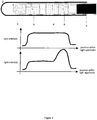
- Figure 3 shows a homogeneous and an inhomogeneous cylindrical radiation profile.
- the homogeneous cylindrical radiation profile preferably has a length along the axis of 1 to 5 cm, more preferably 2 to 4 cm, most preferably 2 to 3 cm. This leads to a reduced light intensity, as compared to the prior art, which conventionally employs a non-areal, but point-shaped light emission by a optic fibre laser tip, thereby applying very high local intensities.
- an inhomogeneous distribution may be reasonable to further reduce the total necessary light energy.
- At the proximal end of the emitting area more light is applied as at the distal end.
- This mode of emitting light causing fast preheating of the tissue at the proximal end, saves energy since the total energy required is somewhat lower when compared to homogenous profile, as e.g. shown in Fig 3a .
- the exact shape of the preferred embodiment is a kind of exponential decay, as this can be easily realized by volume scattering.
- the inhomogeneous cylindrical radiation profile preferably has a length along the axis of 1 to 5 cm, more preferably 2 to 4 cm, most preferably 2 to 3 cm.
- the catheter is for inserting the light applicator into the vessel and for guiding the light applicator within the vessel.
- any conventional catheter may be employed, as long as this catheter is highly transparent for the therapeutic light and inter alia photochemically inert.
- it is made of Teflon or PTFE.
- a catheter this is meant to encompass also any applicator tube in general.
- the catheter in particular the sheath of the catheter, i.e. its tubular envelop, is partially, more preferably fully optically transmissible for light emitted from the light applicator.
- the surface of the catheter or the sheath of the catheter may have a coating, e.g. a hydrophilic coating.
- a hydrophilic coating allows for easier inset into and removing out of the blood vessel.
- the distal end of the catheter is closed. More preferably, also the sheath of the catheter is cylindrical and fully optically transmissible for light emitted from the light applicator.
- the sheath of the catheter may even help, e.g. to homogenize, the radiation profile.
- Catheter and light applicator are arranged and adapted such that in use at any time said light applicator does not make intraluminal contact with any vessel wall.
- the light applicator is placed within the sheath of the catheter, and may be flushed, preferably by a transparent physiological solution.
- the catheter may be open to or in open contact with the fluid within the vessel, although the light applicator does not protrude from the catheter or the catheter sheath and stays safely secured inside the catheter.
- the device may be introduced employing the Seldinger Techniques, i.e. using a guide wire in analogy to classical insertion processes of the prior art as explained above.
- the light applicator is not shifted through the open distal end of the catheter so that the light applicator does not make intraluminal contact with the vessel, i.e. the applicator does not make intraluminal contact with any vessel wall (see also figure 2 , "principle A").
- the catheter in this embodiment is flushable and flushing fluid, preferably an aqueous solution, more preferably a physiological solution may be used to clean and / or cool the light applicator.
- the device may be introduced employing a one step technique, i.e. without using a guide wire. After puncture of the vessel, the catheter is inserted into the vessel (see also figure 2 , "principle B").
- the catheter may or may not encompass the light applicator during the insertion step depending on the rigidity of the device encompassing catheter and light applicator needed.
- the catheter alone is more flexible, while catheter together with light applicator is a more rigid unit.
- the light applicator is intended not to be in contact with blood when in use. These embodiments minimize the risk to create carbonization effects in the vessel, since neither vessel, nor blood are in contact with the light applicator and there is no primary heat of the light applicator as energy is transferred by the emitted light. Also secondary heat within the applicator can be attenuated given by the spacing between light applicator inside the catheter and the (part of the) vessel to be treated.
- the minimal distance from the light applicator tip to the distal end of the catheter is in the range of 1,0 to 30 mm, preferably in the range of 2,0 to 20 mm, more preferably in the range of 3,0 to 10 mm, most preferably in the range of 5,0 to 8,0 mm.
- the light applicator is capable of delivering light energy through the sheath of the catheter and to cause damage to a vessel wall. This delivering of light energy preferably results in a subsequent decrease in the diameter of said vessel wall; most preferably until the shrinkage or collapse of vessel wall.
- the light applicator during use may be placed repeatedly at the same position within the vessel with or without moving the catheter.
- the light applicator is movable within the catheter; more preferably the light applicator is movable within the catheter when in use.
- the light applicator is movable with constant velocity, e.g. with a velocity of 1 to 5 mm/s, preferably 1,0 to 4,0 mm/s, more preferably 2,0 to 3,0 mm/s; most preferably, the velocity is controlled by a velocity control unit.
- Visible pilot light coupled into the applicator, could also be used, for example, to determine the position of the light applicator.
- Other types of labels may be used alternatively, e.g. fluorescent markers.
- the blood vessel treatment device of the invention further comprises an ultrasound, magnetic resonance or radioactive imaging unit for imaging the vessel to be treated; and/ or a velocity control unit for controlling the velocity with which the light applicator is moved within the catheter and /or a temperature or coagulation detecting unit inside the catheter for determining the temperature or tissue properties at the position, where the vessel is damaged and/or an imaging unit, connected to the one or more of the three units above for displaying the data measured by these one or more units.
- a closed loop unit may be present based on the imaging unit, which closed loop unit provides a feedback controlling the parameters light intensity and / or velocity or segmentation of movement.
- Segmentation of movement means that the light applicator is moved stepwise, i.e. moved to one position in the catheter, keep for a short time interval and moved to a next position, and so on.
- the temperature when using the device of the present invention is preferably kept in the range between 37°C and 200 °C, more preferably below 150°C, most preferably below 100°C.
- Each position is preferably "heated” by employing the light applicator for 1 to 25 s, more preferably 2 to15 s, most preferably 5 to10 s. This time range helps to allow a mild treatment, thereby avoiding high temperatures. If more energy needs to be applied to a particular position in order to deliberately damage or shrink the vessel, the light applicator can be moved and used several times to treat the same position.
- the present invention provides a kit comprising one or more light applicators; a catheter for inserting light applicator into and for guiding the light applicator within a vessel; a guide wire; and an access needle, wherein said catheter and said light applicator are arranged and adapted such that in use at any time said light applicator does not make intraluminal contact with any vessel wall and the light applicator is capable of delivering light energy through the sheath of the catheter so as to emit light energy to cause damage to a vessel wall, preferably so as to result in a subsequent decrease in the diameter of said vein wall.
- the kit may be used to prepare the device of the first aspect of the present invention and to insert said device employing the Seldinger Technique.
- the present disclosure provides a method of applying light energy from a light emitting unit to a vessel from within the vessel, the method comprising the steps of: introducing into the vessel the device of the invention and applying energy to the vessel until the vessel is damaged or collapses.
- the light emitting unit may be introduced into the vessel, e.g. in a miniaturized version, it is preferred herein that "introducing into the vessel the device of the invention” means that only the catheter and the light applicator are introduced into the vessel and the light emitting unit, if part of the device, is connected thereto, but stays outside the vessel.
- Collapse or “collapse of the vessel” in particular means that the structure of the vessel, in particular of the wall of the vessel is destroyed, preferably so as to close the vessel from any flood of fluid, preferably from flood of blood.
- “Damage” or “damage of the vessel” preferably means that the structure of the vessel, in particular of the wall of the vessel is altered in its geometry and/or stability.
- the diameter of the vessel decreases when damage of the vessel occurs. In one embodiment, the vessel decreases in its diameter to less than 90% of the original diameter, i.e.
- the vessel decreases in its diameter to less than 85%, to less than 80%, to less than 75%, to less than 70%, to less than 65%, to less than 60%, to less than 55%, to less than 50%, to less than 45%, to less than 40%, to less than 35%, to less than 30%, to less than 25%, to less than 20%, to less than 15%, to less than 10%, to less than 5%, to less than 4%, to less than 3%, to less than 2%, to less than 1% of the diameter before applying the light energy, most preferably it shrinks until the vessel is closed or until no fluid or blood can flow through at the damaged position ("obliteration").
- perivenous tumescence may be used to support the treatment, preferably by administering local anesthesia and/or for reducing the risk of damaging of surrounding tissues, in particular nerve tissues.
- the catheter is withdrawn from the vessel. This may be guided with optical, radioactive or acoustic labels, preferably placed at the distal end of the catheter.
- the method of this third aspect of the disclosure may also be used for damaging a vessel using light energy from a light emitting unit.
- the method of this third aspect of the disclosure further comprises the step of placing the light applicator repeatedly, i.e. at least twice, at the same position in the catheter and therewith in the vessel while continuing to apply energy to the vessel.
- the method comprises the step of moving the light applicator in the catheter and therewith in the vessel while continuing to apply energy to the vessel.
- the method of this third aspect of the disclosure comprises imaging the vessel to be treated, controlling the velocity with which the light applicator is moved within the catheter, or determining the temperature or tissue properties at the position, where the vessel is damaged.
- the device of the present invention can be used in the treatment of varicose veins and, in particular, in connection with a tumescence local anesthesia.
- the shrinking and / or closure of the vein is brought about by a combination of spontaneous contraction, thrombotic closure (on a comparatively small scale) and later fibrotic transformation of the blood vessel and support by secondary effects (such as wound healing).
- secondary effects such as wound healing.
- These biological effects are primarily induced through the effect of heat.
- the absorption of light which causes warming occurs here both in the blood and on the vein wall itself.
- the light in the method described here is emitted on a circular basis and preferably over a particular length. This ensures a more even treatment of the blood vessel.
- a cylindrical irradiation over a length of approx. 0,5-5 cm can sensibly balance out lack of homogeneity in the vessel wall and / or irregularities caused by movement of the applicator.
- this applicator may have a higher level of light emission at the proximal end of its irradiation area. This causes a higher level of energy to be given off at the proximal end of the irradiation area when the light applicator is withdrawn than at the distal end.
- body temperature approximately 37°C
- treatment temperature approximately 60-100°C
- Figure 2 also shows the introduction of the device of the present invention using a one step process ("principle b").
- the catheter itself is used as "guide wire” upon puncture with an access needle and guides the light applicator through the vessel.
- both are inserted simultaneously.
- the light applicator may also be inserted subsequently to the insertion of the catheter.
- the light applicator Upon positioning the catheter, the light applicator is used to apply energy.
- the light applicator is movable within the catheter and is capable of emitting light through the catheter, e.g. through the closed distal end and/or especially through the sheath of the catheter in a cylindrical manner.
- the light applicator may be removed from the catheter. Finally, the catheter is removed from the vessel.
- Inserting the catheter with or without the light applicator may depend upon the rigidity needed.
- the catheter alone is more flexible, while catheter together with light applicator forms a more rigid unit.
- Figure 3 shows exemplary radiation profiles of the light applicator in use.
- the light applicator is a cylindrical diffuser based on a conventional optical fibre 5.
- the upper graph shows a homogeneous cylindrical radiation profile.
- the lower graph shows an inhomogeneous cylindrical radiation profile.
- the profiles can be created for example by the arrangement of different concentration of volume scattering layers (c 1 to c n in the Figure) as desired.
- the figure shows different scatter layers c 1 to c n , each comprising a medium with scattering particles 6) which may be used to set up the radiation profile by coupling out a distinct portion of light.
- the device in figure 3 also shows an embodiment, which comprises a closure 7 of the light applicator.
- a closure 7 of the light applicator e.g. an ultrasound or x-ray label may be placed within the applicator yet outside the light-emitting region for not being absorbing.
Landscapes
- Health & Medical Sciences (AREA)
- Surgery (AREA)
- Physics & Mathematics (AREA)
- Life Sciences & Earth Sciences (AREA)
- Heart & Thoracic Surgery (AREA)
- Medical Informatics (AREA)
- Nuclear Medicine, Radiotherapy & Molecular Imaging (AREA)
- Electromagnetism (AREA)
- Engineering & Computer Science (AREA)
- Biomedical Technology (AREA)
- Optics & Photonics (AREA)
- Otolaryngology (AREA)
- Molecular Biology (AREA)
- Animal Behavior & Ethology (AREA)
- General Health & Medical Sciences (AREA)
- Public Health (AREA)
- Veterinary Medicine (AREA)
- Laser Surgery Devices (AREA)
- Radiation-Therapy Devices (AREA)
- Surgical Instruments (AREA)
Claims (13)
- Eine Vorrichtung für Behandlung von Blutgefäßen, umfassend:a) einen Lichtapplikator (3), verbunden mit einer Licht emittierenden Einheit; undb) einen Katheter (2) zum Einbringen des Lichtapplikators in das Gefäß und zur Führung des Lichtapplikators innerhalb des Gefäßes (1),wobei besagter Katheter und besagter Lichtapplikator so angeordnet und angepasst sind, so dass bei der Verwendung zu jeder Zeit besagter Lichtapplikator keinen intraluminalen Kontakt mit irgendeiner Gefäßwand hat,
der Lichtapplikator in der Lage ist, Lichtenergie durch die Ummantelung des Katheters zuzuführen, so dass Lichtenergie emittiert wird und so die Zerstörung einer Gefäßwand verursacht, die dann in Folge in einer nachfolgenden Verminderung des Durchmessers von besagtem Gefäß resultiert, und
wobei die Leistung der Licht emittierenden Einheit in einem Bereich von 1 bis 150 W, vorzugsweise 10 bis 50 W, liegt. - Die Vorrichtung von Anspruch 1, desweiteren umfassend eine Licht emittierende Einheit, wobei besagte Licht emittierende Einheit mit dem Lichtapplikator verbunden ist.
- Die Vorrichtung von Ansprüchen 1 oder 2, wobei das Licht Laserlicht ist von einer Wellenlänge in einem Bereich von 550-2000 nm.
- Die Vorrichtung von irgendeinem der Ansprüche 1-3, wobei der Lichtapplikator während der Verwendung wiederholt in der gleichen Position innerhalb des Gefäßes platziert sein kann, ohne dass der Katheter bewegt wird.
- Die Vorrichtung von Anspruch 4, wobei der Lichtapplikator während der Verwendung beweglich innerhalb des Katheters ist mit einer konstanten Geschwindigkeit v mit v = 1-5 mm/s oder beweglich ist in nachfolgenden Segmenten.
- Die Vorrichtung von irgendeinem der Ansprüche 1-5, wobei der Lichtapplikator innerhalb der Ummantelung des Katheters platziert ist und der Katheter am distalen Ende geschlossen ist, wobei vorzugsweise der minimale Abstand der Lichtapplikatorspitze zum distalen Ende des Katheters 1,0-30 mm beträgt.
- Die Vorrichtung von irgendeinem der Ansprüche 1-5, wobei der Lichtapplikator innerhalb der Ummantelung des Katheters platziert ist und der Katheter am distalen Ende offen ist.
- Die Vorrichtung von Anspruch 7, welche anwendbar ist für das Blutgefäß unter Verwendung der Seldinger-Technik oder einer Art einer Seldinger-Technik.
- Die Vorrichtung von irgendeinem der Ansprüche 1-8, wobei der Durchmesser des Lichtapplikators zwischen 0,1 und 2,5 mm beträgt.
- Die Vorrichtung von irgendeinem der Ansprüche 1-9, wobei der Lichtapplikator eine Faseroptikleiter ist, vorzugsweise umfassend einen zylindrischen Diffuser.
- Die Vorrichtung von irgendeinem der Ansprüche 1-10, wobei der Lichtapplikator Licht in einen zylindrischen Strahlungsprofil emittiert und vorzugsweise eine Länge entlang der Achse von 1 bis 5 cm hat.
- Die Vorrichtung von irgendeinem der Ansprüche 1-11, desweiteren umfassenda) eine Ultraschall-, magnetische Resonanz- oder radioaktive oder andere Kontrast-Einheit zur Bildgebung der Vorrichtung und des Gefäßes, das behandelt werden soll; und/oderb) eine Geschwindigkeitssteuer-Einheit zur Steuerung der Geschwindigkeit, mit welcher der Lichtapplikator innerhalb des Katheters bewegt wird; und/oderc) eine Temperatur- oder Koagulations-Mess-Einheit, innerhalb oder auf der Oberfläche des Katheters und/oder einen Applikator zur Bestimmung der Temperatur an der Position, wo das Gefäß beschädigt werden soll;d) eine bildgebende Einheit, verbunden mit den Einheiten von einer oder mehreren von a) bis c) zur Anzeige der Daten, gemessen durch besagte Einheiten a) bis c); und/odere) eine geschlossene Schleifen-Einheit, basierend auf der Rückkopplung d), welche die Parameter Lichtintensität und/oder Geschwindigkeit oder Segmentation der Bewegung steuert.
- Ein Kit, umfassenda) einen oder mehrere Lichtapplikatoren;b) einen oder mehrere Katheter zum Einbringen des Lichtapplikators in ein Gefäß und zum Führen des Lichtapplikators innerhalb eines Gefäßes;c) eine Zugangsnadel; undd) optional einen Leitungsdraht,wobei besagter Katheter und besagter Lichtapplikator angeordnet und angepasst sind, so dass bei der Verwendung zu jeder Zeit der Lichtapplikator keinen interluminalen Kontakt mit irgendeiner Gefäßwand hat,
der Lichtapplikator in der Lage ist, Lichtenergie durch die Ummantelung des Katheters zuzuführen, so dass Lichtenergie emittiert wird und so die Beschädigung einer Gefäßwand verursacht, die dann in einer nachfolgenden Verminderung des Durchmessers von besagtem Gefäß resultiert, und
wobei die Leistung der Licht emittierenden Einheit, verknüpft mit dem Lichtapplikator, in einem Bereich von 1 bis 150 W, vorzugsweise 10 bis 50 W, liegt.
Applications Claiming Priority (2)
| Application Number | Priority Date | Filing Date | Title |
|---|---|---|---|
| US4777908P | 2008-04-25 | 2008-04-25 | |
| PCT/EP2009/003027 WO2009130049A1 (en) | 2008-04-25 | 2009-04-24 | Light-based method for the endovascular treatment of pathologically altered blood vessels |
Publications (2)
| Publication Number | Publication Date |
|---|---|
| EP2268223A1 EP2268223A1 (de) | 2011-01-05 |
| EP2268223B1 true EP2268223B1 (de) | 2019-01-02 |
Family
ID=40888204
Family Applications (1)
| Application Number | Title | Priority Date | Filing Date |
|---|---|---|---|
| EP09734317.2A Active EP2268223B1 (de) | 2008-04-25 | 2009-04-24 | Lichtbasiertes gerät zur endovaskulären behandlung pathologisch veränderter blutgefässe |
Country Status (4)
| Country | Link |
|---|---|
| US (2) | US9149334B2 (de) |
| EP (1) | EP2268223B1 (de) |
| ES (1) | ES2710180T3 (de) |
| WO (1) | WO2009130049A1 (de) |
Families Citing this family (1)
| Publication number | Priority date | Publication date | Assignee | Title |
|---|---|---|---|---|
| US9108030B2 (en) * | 2013-03-14 | 2015-08-18 | Covidien Lp | Fluid delivery catheter with pressure-actuating needle deployment and retraction |
Family Cites Families (101)
| Publication number | Priority date | Publication date | Assignee | Title |
|---|---|---|---|---|
| DE8416748U1 (de) | 1984-08-30 | Messerschmitt-Bölkow-Blohm GmbH, 8012 Ottobrunn | Lichtleitereinkopplung für ein medizinisches Lasergerät | |
| US4519390A (en) * | 1982-10-15 | 1985-05-28 | Hgm, Inc. | Fiber optic laser catheter |
| US4722337A (en) * | 1983-08-22 | 1988-02-02 | Laserscope | Medical laser peripherals and connector system |
| US4693244A (en) * | 1984-05-22 | 1987-09-15 | Surgical Laser Technologies, Inc. | Medical and surgical laser probe I |
| US4592353A (en) * | 1984-05-22 | 1986-06-03 | Surgical Laser Technologies Ohio, Inc. | Medical and surgical laser probe |
| US5693043A (en) * | 1985-03-22 | 1997-12-02 | Massachusetts Institute Of Technology | Catheter for laser angiosurgery |
| US4736743A (en) * | 1986-05-12 | 1988-04-12 | Surgical Laser Technology, Inc. | Vaporization contact laser probe |
| US4781185A (en) * | 1986-07-21 | 1988-11-01 | Gv Medical, Inc. | Connecting apparatus for catheter assembly |
| US5200230A (en) * | 1987-06-29 | 1993-04-06 | Dunfries Investments Limited | Laser coating process |
| GB8725566D0 (en) * | 1987-10-31 | 1987-12-02 | Pilkington Medical Systems Ltd | Laser system |
| US4822997A (en) * | 1987-11-04 | 1989-04-18 | Fullen Research Corporation | Apparatus for and method of measuring and/or controlling the use of fiber optic conductors |
| US5071222A (en) * | 1987-12-29 | 1991-12-10 | Luxar Corporation | Lightpipe tip for contact laser surgery |
| US4852567A (en) | 1988-01-21 | 1989-08-01 | C. R. Bard, Inc. | Laser tipped catheter |
| US5112328A (en) * | 1988-01-25 | 1992-05-12 | Refractive Laser Research & Development Program, Ltd. | Method and apparatus for laser surgery |
| EP0368512A3 (de) * | 1988-11-10 | 1990-08-08 | Premier Laser Systems, Inc. | Medizinischer Laser mit variabler Wellenlänge |
| JP2681073B2 (ja) | 1989-01-17 | 1997-11-19 | 則雄 大工園 | レーザ光出射プローブとその製造方法 |
| JP2940940B2 (ja) | 1989-06-30 | 1999-08-25 | ホーヤ株式会社 | レーザ光伝送装置及び医療用レーザ装置 |
| JP3145379B2 (ja) | 1989-06-30 | 2001-03-12 | 株式会社エス・エル・ティ・ジャパン | レーザ導光プローブ |
| DE3934647C2 (de) * | 1989-10-17 | 1994-05-26 | Deutsche Aerospace | Chirurgisches Laserinstrument |
| US5133035A (en) * | 1989-11-14 | 1992-07-21 | Hicks John W | Multifiber endoscope with multiple scanning modes to produce an image free of fixed pattern noise |
| IL97130A (en) * | 1990-02-07 | 1995-07-31 | Coherent Inc | Transmission system while in contact with laser |
| DE4013455A1 (de) | 1990-04-27 | 1991-10-31 | Philips Patentverwaltung | Optisches steckerelement und verfahren zu seiner herstellung |
| US5154708A (en) * | 1990-05-15 | 1992-10-13 | Surgical Laser Technologies, Inc. | Unitary scalpel for contact laser surgery |
| US5490849A (en) * | 1990-07-13 | 1996-02-13 | Smith; Robert F. | Uniform-radiation caustic surface for photoablation |
| DE4025851A1 (de) | 1990-08-16 | 1992-02-20 | Messerschmitt Boelkow Blohm | Einrichtung zur messung rueckgestreuter strahlung |
| DE4026452C2 (de) | 1990-08-21 | 1993-12-02 | Schott Glaswerke | Vorrichtung zur Erkennung und Unterscheidung von unter eine Steckverbindung an einen Laser anschließbaren medizinischen Einwegapplikatoren |
| DE9013085U1 (de) | 1990-09-14 | 1990-11-15 | Souriau Electric Gmbh, 4006 Erkrath | Kalibrierstecker für einen faseroptischen Lichtwellenleiter |
| US5157747A (en) | 1991-01-18 | 1992-10-20 | At&T Bell Laboratories | Photorefractive optical fiber |
| CA2066963A1 (en) | 1991-05-15 | 1992-11-16 | Norio Daikuzono | Laser light irradiation apparatus |
| US5333603A (en) * | 1992-02-25 | 1994-08-02 | Daniel Schuman | Endoscope with palm rest |
| EP0637942B1 (de) * | 1992-04-24 | 1999-05-06 | Surgical Laser Technologies, Inc. | Medizinische vorrichtung |
| EP0680283B1 (de) * | 1992-04-24 | 1998-05-13 | Surgical Laser Technologies | Thermisch resistente medizinische sonde |
| DE4216254C2 (de) | 1992-05-16 | 1994-08-18 | Heraeus Kulzer Gmbh | Lichtleiter für ein Bestrahlungsgerät |
| DE4229566C2 (de) | 1992-09-04 | 1996-08-29 | Rosenberger Hochfrequenztech | Verfahren und Vorrichtung zur automatischen Erkennung eines über eine Stecker-Buchsenverbindung an ein Versorgungsgerät angeschlossenen Anschlußgerätes |
| US5409483A (en) * | 1993-01-22 | 1995-04-25 | Jeffrey H. Reese | Direct visualization surgical probe |
| US5360447A (en) * | 1993-02-03 | 1994-11-01 | Coherent, Inc. | Laser assisted hair transplant method |
| DE4403134A1 (de) * | 1993-05-14 | 1995-08-03 | Laser Medizin Zentrum Ggmbh Be | Kombinationsvorrichtung zur thermischen Verödung biologischen Gewebes |
| DE4318237A1 (de) * | 1993-06-01 | 1994-12-08 | Storz Medical Ag | Vorrichtung zur Behandlung von biologischem Gewebe und Körperkonkrementen |
| US5397327A (en) * | 1993-07-27 | 1995-03-14 | Coherent, Inc. | Surgical laser handpiece for slit incisions |
| US5416878A (en) * | 1993-07-29 | 1995-05-16 | Endeavor Surgical Products, Inc. | Surgical methods and apparatus using a bent-tip side-firing laser fiber |
| US5535399A (en) * | 1993-09-30 | 1996-07-09 | Quantum Corporation | Solid state disk drive unit having on-board backup non-volatile memory |
| US5690611A (en) * | 1994-07-08 | 1997-11-25 | Daig Corporation | Process for the treatment of atrial arrhythima using a catheter guided by shaped giding introducers |
| US8025661B2 (en) * | 1994-09-09 | 2011-09-27 | Cardiofocus, Inc. | Coaxial catheter instruments for ablation with radiant energy |
| US6423055B1 (en) * | 1999-07-14 | 2002-07-23 | Cardiofocus, Inc. | Phototherapeutic wave guide apparatus |
| US5681307A (en) * | 1994-10-26 | 1997-10-28 | Mcmahan; William H. | Fiber-optic plug and receptacle providing automatic appliance recognition |
| EP0717964A1 (de) * | 1994-12-22 | 1996-06-26 | Dornier Medizintechnik GmbH | Laserchirurgischer Applikator |
| US5743902A (en) * | 1995-01-23 | 1998-04-28 | Coherent, Inc. | Hand-held laser scanner |
| US6567582B1 (en) * | 1995-08-31 | 2003-05-20 | Biolase Tech Inc | Fiber tip fluid output device |
| DE19534590A1 (de) | 1995-09-11 | 1997-03-13 | Laser & Med Tech Gmbh | Scanning Ablation von keramischen Werkstoffen, Kunststoffen und biologischen Hydroxylapatitmaterialien, insbesondere Zahnhartsubstanz |
| US5860972A (en) * | 1995-10-26 | 1999-01-19 | Xintec Corporation | Method of detection and destruction of urinary calculi and similar structures |
| US5841562A (en) * | 1995-12-28 | 1998-11-24 | Lucent Technologies, Inc. | Bidirectional modular optoelectronic transceiver assembly |
| US5872618A (en) * | 1996-02-28 | 1999-02-16 | Nikon Corporation | Projection exposure apparatus |
| US5908417A (en) * | 1996-03-29 | 1999-06-01 | Fotona D.D. | Method and apparatus for laser-assisted hair transplantation |
| US5738679A (en) * | 1996-06-26 | 1998-04-14 | S.L.T. Japan Company Limited | Apparatus for laser treatment for living tissue |
| DE19629646C2 (de) | 1996-07-23 | 1998-09-10 | Wolf Gmbh Richard | Verfahren und Vorrichtung zur automatischen Identifikation von Komponenten medizinischer Gerätesysteme |
| US5797868A (en) * | 1996-07-25 | 1998-08-25 | Cordis Corporation | Photodynamic therapy balloon catheter |
| US5742718A (en) * | 1996-08-13 | 1998-04-21 | Eclipse Surgical Technologies, Inc. | Proprietary fiber connector and electronic security system |
| DE19636265B4 (de) * | 1996-09-06 | 2007-09-20 | Kaltenbach & Voigt Gmbh | Laserinstrument |
| US5782896A (en) * | 1997-01-29 | 1998-07-21 | Light Sciences Limited Partnership | Use of a shape memory alloy to modify the disposition of a device within an implantable medical probe |
| DE19710676C2 (de) * | 1997-03-16 | 1999-06-02 | Aesculap Meditec Gmbh | Anordnung zur Photoablation |
| AU8755898A (en) | 1997-04-11 | 1998-11-11 | Digital Optics Corporation | Optical transmission systems including optical rods with three-dimensional patterns thereon and related structures |
| US5951543A (en) * | 1997-06-30 | 1999-09-14 | Clinicon Corporation | Delivery system and method for surgical laser |
| DE19729978A1 (de) | 1997-07-12 | 1999-01-14 | Bayerische Motoren Werke Ag | Vorrichtung zum lösbaren Verbinden zweier Lichtleiter oder Lichtleiterbündel miteinander |
| US6273885B1 (en) * | 1997-08-16 | 2001-08-14 | Cooltouch Corporation | Handheld photoepilation device and method |
| EP1017451A1 (de) | 1997-09-24 | 2000-07-12 | United States Surgical Corporation | Geräte und verfahren zur durchführungtransmyokardialer revaskularisierung |
| US6193711B1 (en) * | 1997-12-12 | 2001-02-27 | Coherent, Inc. | Rapid pulsed Er:YAG laser |
| US6669694B2 (en) * | 2000-09-05 | 2003-12-30 | John H. Shadduck | Medical instruments and techniques for highly-localized thermally-mediated therapies |
| DE19821986C1 (de) * | 1998-05-18 | 2000-07-06 | Dornier Medtech Holding Int Gmbh | Laserinstrument |
| US6377591B1 (en) * | 1998-12-09 | 2002-04-23 | Mcdonnell Douglas Corporation | Modularized fiber optic laser system and associated optical amplification modules |
| US6398777B1 (en) * | 1999-02-01 | 2002-06-04 | Luis Navarro | Endovascular laser device and treatment of varicose veins |
| US6270491B1 (en) * | 1999-04-06 | 2001-08-07 | Duke University | Intensity controllable hand-held surgical light |
| US6398778B1 (en) * | 1999-06-18 | 2002-06-04 | Photonics Research Ontario | Optical fiber diffuser |
| DE10009004A1 (de) | 2000-02-25 | 2001-10-11 | Oralia Dentalprodukte Gmbh | Modularer Laserapplikator |
| DE10106297A1 (de) | 2000-06-08 | 2002-01-03 | Schleifring Und Appbau Gmbh | Optisches Datenübertragungssystem |
| US6477426B1 (en) * | 2000-06-20 | 2002-11-05 | Celsion Corporation | System and method for heating the prostate gland to treat and prevent the growth and spread of prostate tumors |
| AU2002245163A1 (en) * | 2000-10-20 | 2002-07-24 | Photomedex | Controlled dose delivery of ultraviolet light for treating skin disorders |
| US6829427B1 (en) * | 2000-10-24 | 2004-12-07 | Biolase Technology, Inc. | Fiber detector apparatus and related methods |
| JP4730490B2 (ja) | 2000-11-24 | 2011-07-20 | 大日本印刷株式会社 | 表示機能を持つ光ファイバーの作製方法 |
| US20020073082A1 (en) * | 2000-12-12 | 2002-06-13 | Edouard Duvillier | System modification processing technique implemented on an information storage and retrieval system |
| US20030130649A1 (en) * | 2000-12-15 | 2003-07-10 | Murray Steven C. | Method and system for treatment of benign prostatic hypertrophy (BPH) |
| WO2002052322A1 (en) * | 2000-12-22 | 2002-07-04 | Asah Medico A/S | An optical fibre connector assembly |
| US6986766B2 (en) * | 2001-06-15 | 2006-01-17 | Diomed Inc. | Method of endovenous laser treatment |
| WO2003005889A2 (en) * | 2001-07-10 | 2003-01-23 | Ams Research Corporation | Surgical kit for treating prostate tissue |
| AU2003251566A1 (en) * | 2002-06-19 | 2004-01-06 | Angiodynamics, Inc. | Endovascular treatment device with a protective sleeve |
| US7458967B2 (en) * | 2003-10-31 | 2008-12-02 | Angiodynamics, Inc. | Endovascular treatment apparatus and method |
| US6821025B2 (en) * | 2002-07-18 | 2004-11-23 | Westover Scientific, Inc. | Fiber-optic endface cleaning assembly and method |
| WO2004012805A2 (en) * | 2002-08-05 | 2004-02-12 | Miravant Medical Technologies | Light delivery catheter |
| DE10236175B4 (de) * | 2002-08-07 | 2005-05-19 | Dornier Medtech Systems Gmbh | Lasersystem mit fasergebundener Kommunikation |
| DE10245140B4 (de) * | 2002-09-27 | 2005-10-20 | Dornier Medtech Laser Gmbh | Intelligente Therapiefaser |
| AU2003287511A1 (en) * | 2002-10-31 | 2004-05-25 | Cooltouch, Incorporated | Endovenous closure of varicose veins with mid infrared laser |
| US7524316B2 (en) * | 2002-10-31 | 2009-04-28 | Cooltouch, Inc. | Endovenous closure of varicose veins with mid infrared laser |
| US7644715B2 (en) * | 2002-10-31 | 2010-01-12 | Cooltouch, Incorporated | Restless leg syndrome treatment |
| US20040199151A1 (en) * | 2003-04-03 | 2004-10-07 | Ceramoptec Industries, Inc. | Power regulated medical underskin irradiation treament system |
| US6926450B2 (en) * | 2003-07-16 | 2005-08-09 | Chen-Hung Hung | Optical connector |
| FR2864255B1 (fr) * | 2003-12-19 | 2006-02-24 | Inst Francais Du Petrole | Dispositif de connexion pour fibre optique |
| DE102005017798A1 (de) * | 2005-04-18 | 2006-11-09 | Dornier Medtech Laser Gmbh | Lichtleitfaser |
| US7492987B2 (en) * | 2005-12-19 | 2009-02-17 | Trimedyne, Inc. | Fiber optic laser energy delivery devices |
| EP1996106B1 (de) * | 2006-03-13 | 2014-04-30 | Bruno Anastasie | Laserinstrument für den gefässverschluss, insbesondere für intravenöse behandlung und zur perforation oder detersion von gewebe |
| US8876810B2 (en) * | 2006-03-20 | 2014-11-04 | Biolitec Pharma Marketing Ltd | Benign prostatic hyperplasia treatment method and device |
| US7215864B1 (en) * | 2006-07-24 | 2007-05-08 | All Optronics, Inc. | Low-cost portable fiber-optic connector cleaner |
| US20080033341A1 (en) * | 2006-08-04 | 2008-02-07 | Bay Holdings Ltd. | Methods and devices for reducing or blocking blood flow to a selected blood vessel or part thereof |
-
2009
- 2009-04-24 EP EP09734317.2A patent/EP2268223B1/de active Active
- 2009-04-24 ES ES09734317T patent/ES2710180T3/es active Active
- 2009-04-24 WO PCT/EP2009/003027 patent/WO2009130049A1/en not_active Ceased
-
2010
- 2010-10-25 US US12/911,613 patent/US9149334B2/en active Active
-
2013
- 2013-06-10 US US13/914,078 patent/US9168098B2/en active Active
Non-Patent Citations (1)
| Title |
|---|
| None * |
Also Published As
| Publication number | Publication date |
|---|---|
| EP2268223A1 (de) | 2011-01-05 |
| ES2710180T3 (es) | 2019-04-23 |
| US20110125140A1 (en) | 2011-05-26 |
| US20130289547A1 (en) | 2013-10-31 |
| WO2009130049A1 (en) | 2009-10-29 |
| US9168098B2 (en) | 2015-10-27 |
| US9149334B2 (en) | 2015-10-06 |
Similar Documents
| Publication | Publication Date | Title |
|---|---|---|
| US7524316B2 (en) | Endovenous closure of varicose veins with mid infrared laser | |
| US8257347B2 (en) | Vein treatment device and method | |
| CA2199384C (en) | Phototherapeutic apparatus | |
| JP2023133510A (ja) | 血管腔内治療装置 | |
| US20070282301A1 (en) | Dilatation Balloon Catheter Including External Means For Endoluminal Therapy And For Drug Activation | |
| US20070049911A1 (en) | Endovascular method and apparatus with feedback | |
| Sroka et al. | Endovenous laser therapy–application studies and latest investigations | |
| US20080208180A1 (en) | Endovascular treatment sheath having a heat insulative tip and method for using the same | |
| US8454586B2 (en) | Laser instrument for vascular occlusion, in particular for intravenous treatment, and for perforation or detersion of tissue | |
| EP2268223B1 (de) | Lichtbasiertes gerät zur endovaskulären behandlung pathologisch veränderter blutgefässe | |
| US20110130749A1 (en) | Method of endovenous laser treatment of varicose veins | |
| US20250143791A1 (en) | Systems, devices and methods for targeted tissue therapy | |
| US9149335B2 (en) | Contact free and perforation safe endoluminal laser treatment device and method | |
| US11129676B2 (en) | Device and method for vessel treatment | |
| EP1527798A2 (de) | Diffusionspritzskörper. | |
| KR102680892B1 (ko) | 치루 치료기 | |
| WO2026078263A1 (en) | Endovascular catheter system for targeted photothermal ablation of perivascular nerves | |
| WO1999042168A2 (en) | Method of intravascular electromagnetic radiation treatment | |
| AU5195700A (en) | Phototherapeutic apparatus |
Legal Events
| Date | Code | Title | Description |
|---|---|---|---|
| PUAI | Public reference made under article 153(3) epc to a published international application that has entered the european phase |
Free format text: ORIGINAL CODE: 0009012 |
|
| 17P | Request for examination filed |
Effective date: 20101025 |
|
| AK | Designated contracting states |
Kind code of ref document: A1 Designated state(s): AT BE BG CH CY CZ DE DK EE ES FI FR GB GR HR HU IE IS IT LI LT LU LV MC MK MT NL NO PL PT RO SE SI SK TR |
|
| AX | Request for extension of the european patent |
Extension state: AL BA RS |
|
| DAX | Request for extension of the european patent (deleted) | ||
| 17Q | First examination report despatched |
Effective date: 20140206 |
|
| STAA | Information on the status of an ep patent application or granted ep patent |
Free format text: STATUS: EXAMINATION IS IN PROGRESS |
|
| GRAP | Despatch of communication of intention to grant a patent |
Free format text: ORIGINAL CODE: EPIDOSNIGR1 |
|
| STAA | Information on the status of an ep patent application or granted ep patent |
Free format text: STATUS: GRANT OF PATENT IS INTENDED |
|
| INTG | Intention to grant announced |
Effective date: 20180726 |
|
| GRAS | Grant fee paid |
Free format text: ORIGINAL CODE: EPIDOSNIGR3 |
|
| GRAA | (expected) grant |
Free format text: ORIGINAL CODE: 0009210 |
|
| STAA | Information on the status of an ep patent application or granted ep patent |
Free format text: STATUS: THE PATENT HAS BEEN GRANTED |
|
| AK | Designated contracting states |
Kind code of ref document: B1 Designated state(s): AT BE BG CH CY CZ DE DK EE ES FI FR GB GR HR HU IE IS IT LI LT LU LV MC MK MT NL NO PL PT RO SE SI SK TR |
|
| REG | Reference to a national code |
Ref country code: GB Ref legal event code: FG4D |
|
| REG | Reference to a national code |
Ref country code: CH Ref legal event code: EP Ref country code: AT Ref legal event code: REF Ref document number: 1083426 Country of ref document: AT Kind code of ref document: T Effective date: 20190115 |
|
| REG | Reference to a national code |
Ref country code: IE Ref legal event code: FG4D |
|
| REG | Reference to a national code |
Ref country code: DE Ref legal event code: R096 Ref document number: 602009056504 Country of ref document: DE |
|
| REG | Reference to a national code |
Ref country code: ES Ref legal event code: FG2A Ref document number: 2710180 Country of ref document: ES Kind code of ref document: T3 Effective date: 20190423 |
|
| REG | Reference to a national code |
Ref country code: NL Ref legal event code: MP Effective date: 20190102 |
|
| REG | Reference to a national code |
Ref country code: LT Ref legal event code: MG4D |
|
| REG | Reference to a national code |
Ref country code: AT Ref legal event code: MK05 Ref document number: 1083426 Country of ref document: AT Kind code of ref document: T Effective date: 20190102 |
|
| PG25 | Lapsed in a contracting state [announced via postgrant information from national office to epo] |
Ref country code: NL Free format text: LAPSE BECAUSE OF FAILURE TO SUBMIT A TRANSLATION OF THE DESCRIPTION OR TO PAY THE FEE WITHIN THE PRESCRIBED TIME-LIMIT Effective date: 20190102 |
|
| PG25 | Lapsed in a contracting state [announced via postgrant information from national office to epo] |
Ref country code: SE Free format text: LAPSE BECAUSE OF FAILURE TO SUBMIT A TRANSLATION OF THE DESCRIPTION OR TO PAY THE FEE WITHIN THE PRESCRIBED TIME-LIMIT Effective date: 20190102 Ref country code: PT Free format text: LAPSE BECAUSE OF FAILURE TO SUBMIT A TRANSLATION OF THE DESCRIPTION OR TO PAY THE FEE WITHIN THE PRESCRIBED TIME-LIMIT Effective date: 20190502 Ref country code: FI Free format text: LAPSE BECAUSE OF FAILURE TO SUBMIT A TRANSLATION OF THE DESCRIPTION OR TO PAY THE FEE WITHIN THE PRESCRIBED TIME-LIMIT Effective date: 20190102 Ref country code: NO Free format text: LAPSE BECAUSE OF FAILURE TO SUBMIT A TRANSLATION OF THE DESCRIPTION OR TO PAY THE FEE WITHIN THE PRESCRIBED TIME-LIMIT Effective date: 20190402 Ref country code: LT Free format text: LAPSE BECAUSE OF FAILURE TO SUBMIT A TRANSLATION OF THE DESCRIPTION OR TO PAY THE FEE WITHIN THE PRESCRIBED TIME-LIMIT Effective date: 20190102 Ref country code: PL Free format text: LAPSE BECAUSE OF FAILURE TO SUBMIT A TRANSLATION OF THE DESCRIPTION OR TO PAY THE FEE WITHIN THE PRESCRIBED TIME-LIMIT Effective date: 20190102 |
|
| PG25 | Lapsed in a contracting state [announced via postgrant information from national office to epo] |
Ref country code: IS Free format text: LAPSE BECAUSE OF FAILURE TO SUBMIT A TRANSLATION OF THE DESCRIPTION OR TO PAY THE FEE WITHIN THE PRESCRIBED TIME-LIMIT Effective date: 20190502 Ref country code: GR Free format text: LAPSE BECAUSE OF FAILURE TO SUBMIT A TRANSLATION OF THE DESCRIPTION OR TO PAY THE FEE WITHIN THE PRESCRIBED TIME-LIMIT Effective date: 20190403 Ref country code: HR Free format text: LAPSE BECAUSE OF FAILURE TO SUBMIT A TRANSLATION OF THE DESCRIPTION OR TO PAY THE FEE WITHIN THE PRESCRIBED TIME-LIMIT Effective date: 20190102 Ref country code: LV Free format text: LAPSE BECAUSE OF FAILURE TO SUBMIT A TRANSLATION OF THE DESCRIPTION OR TO PAY THE FEE WITHIN THE PRESCRIBED TIME-LIMIT Effective date: 20190102 Ref country code: BG Free format text: LAPSE BECAUSE OF FAILURE TO SUBMIT A TRANSLATION OF THE DESCRIPTION OR TO PAY THE FEE WITHIN THE PRESCRIBED TIME-LIMIT Effective date: 20190402 |
|
| REG | Reference to a national code |
Ref country code: DE Ref legal event code: R097 Ref document number: 602009056504 Country of ref document: DE |
|
| PG25 | Lapsed in a contracting state [announced via postgrant information from national office to epo] |
Ref country code: CZ Free format text: LAPSE BECAUSE OF FAILURE TO SUBMIT A TRANSLATION OF THE DESCRIPTION OR TO PAY THE FEE WITHIN THE PRESCRIBED TIME-LIMIT Effective date: 20190102 Ref country code: RO Free format text: LAPSE BECAUSE OF FAILURE TO SUBMIT A TRANSLATION OF THE DESCRIPTION OR TO PAY THE FEE WITHIN THE PRESCRIBED TIME-LIMIT Effective date: 20190102 Ref country code: EE Free format text: LAPSE BECAUSE OF FAILURE TO SUBMIT A TRANSLATION OF THE DESCRIPTION OR TO PAY THE FEE WITHIN THE PRESCRIBED TIME-LIMIT Effective date: 20190102 Ref country code: DK Free format text: LAPSE BECAUSE OF FAILURE TO SUBMIT A TRANSLATION OF THE DESCRIPTION OR TO PAY THE FEE WITHIN THE PRESCRIBED TIME-LIMIT Effective date: 20190102 Ref country code: AT Free format text: LAPSE BECAUSE OF FAILURE TO SUBMIT A TRANSLATION OF THE DESCRIPTION OR TO PAY THE FEE WITHIN THE PRESCRIBED TIME-LIMIT Effective date: 20190102 Ref country code: SK Free format text: LAPSE BECAUSE OF FAILURE TO SUBMIT A TRANSLATION OF THE DESCRIPTION OR TO PAY THE FEE WITHIN THE PRESCRIBED TIME-LIMIT Effective date: 20190102 |
|
| PLBE | No opposition filed within time limit |
Free format text: ORIGINAL CODE: 0009261 |
|
| STAA | Information on the status of an ep patent application or granted ep patent |
Free format text: STATUS: NO OPPOSITION FILED WITHIN TIME LIMIT |
|
| REG | Reference to a national code |
Ref country code: CH Ref legal event code: PL |
|
| 26N | No opposition filed |
Effective date: 20191003 |
|
| REG | Reference to a national code |
Ref country code: BE Ref legal event code: MM Effective date: 20190430 |
|
| GBPC | Gb: european patent ceased through non-payment of renewal fee |
Effective date: 20190424 |
|
| PG25 | Lapsed in a contracting state [announced via postgrant information from national office to epo] |
Ref country code: LU Free format text: LAPSE BECAUSE OF NON-PAYMENT OF DUE FEES Effective date: 20190424 Ref country code: MC Free format text: LAPSE BECAUSE OF FAILURE TO SUBMIT A TRANSLATION OF THE DESCRIPTION OR TO PAY THE FEE WITHIN THE PRESCRIBED TIME-LIMIT Effective date: 20190102 |
|
| PG25 | Lapsed in a contracting state [announced via postgrant information from national office to epo] |
Ref country code: CH Free format text: LAPSE BECAUSE OF NON-PAYMENT OF DUE FEES Effective date: 20190430 Ref country code: GB Free format text: LAPSE BECAUSE OF NON-PAYMENT OF DUE FEES Effective date: 20190424 Ref country code: LI Free format text: LAPSE BECAUSE OF NON-PAYMENT OF DUE FEES Effective date: 20190430 |
|
| PG25 | Lapsed in a contracting state [announced via postgrant information from national office to epo] |
Ref country code: SI Free format text: LAPSE BECAUSE OF FAILURE TO SUBMIT A TRANSLATION OF THE DESCRIPTION OR TO PAY THE FEE WITHIN THE PRESCRIBED TIME-LIMIT Effective date: 20190102 Ref country code: BE Free format text: LAPSE BECAUSE OF NON-PAYMENT OF DUE FEES Effective date: 20190430 |
|
| PG25 | Lapsed in a contracting state [announced via postgrant information from national office to epo] |
Ref country code: TR Free format text: LAPSE BECAUSE OF FAILURE TO SUBMIT A TRANSLATION OF THE DESCRIPTION OR TO PAY THE FEE WITHIN THE PRESCRIBED TIME-LIMIT Effective date: 20190102 |
|
| PG25 | Lapsed in a contracting state [announced via postgrant information from national office to epo] |
Ref country code: IE Free format text: LAPSE BECAUSE OF NON-PAYMENT OF DUE FEES Effective date: 20190424 |
|
| PG25 | Lapsed in a contracting state [announced via postgrant information from national office to epo] |
Ref country code: CY Free format text: LAPSE BECAUSE OF FAILURE TO SUBMIT A TRANSLATION OF THE DESCRIPTION OR TO PAY THE FEE WITHIN THE PRESCRIBED TIME-LIMIT Effective date: 20190102 |
|
| PG25 | Lapsed in a contracting state [announced via postgrant information from national office to epo] |
Ref country code: HU Free format text: LAPSE BECAUSE OF FAILURE TO SUBMIT A TRANSLATION OF THE DESCRIPTION OR TO PAY THE FEE WITHIN THE PRESCRIBED TIME-LIMIT; INVALID AB INITIO Effective date: 20090424 Ref country code: MT Free format text: LAPSE BECAUSE OF FAILURE TO SUBMIT A TRANSLATION OF THE DESCRIPTION OR TO PAY THE FEE WITHIN THE PRESCRIBED TIME-LIMIT Effective date: 20190102 |
|
| PG25 | Lapsed in a contracting state [announced via postgrant information from national office to epo] |
Ref country code: MK Free format text: LAPSE BECAUSE OF FAILURE TO SUBMIT A TRANSLATION OF THE DESCRIPTION OR TO PAY THE FEE WITHIN THE PRESCRIBED TIME-LIMIT Effective date: 20190102 |
|
| REG | Reference to a national code |
Ref country code: DE Ref legal event code: R081 Ref document number: 602009056504 Country of ref document: DE Owner name: DORNIER MEDTECH SYSTEMS GMBH, DE Free format text: FORMER OWNER: DORNIER MEDTECH LASER GMBH, 82234 WESSLING, DE |
|
| PGFP | Annual fee paid to national office [announced via postgrant information from national office to epo] |
Ref country code: DE Payment date: 20250425 Year of fee payment: 17 |
|
| PGFP | Annual fee paid to national office [announced via postgrant information from national office to epo] |
Ref country code: ES Payment date: 20250505 Year of fee payment: 17 |
|
| PGFP | Annual fee paid to national office [announced via postgrant information from national office to epo] |
Ref country code: IT Payment date: 20250428 Year of fee payment: 17 |
|
| PGFP | Annual fee paid to national office [announced via postgrant information from national office to epo] |
Ref country code: FR Payment date: 20250426 Year of fee payment: 17 |