EP2268402B1 - Porte-échantillon et son procédé d'utilisation - Google Patents
Porte-échantillon et son procédé d'utilisation Download PDFInfo
- Publication number
- EP2268402B1 EP2268402B1 EP09727143.1A EP09727143A EP2268402B1 EP 2268402 B1 EP2268402 B1 EP 2268402B1 EP 09727143 A EP09727143 A EP 09727143A EP 2268402 B1 EP2268402 B1 EP 2268402B1
- Authority
- EP
- European Patent Office
- Prior art keywords
- sample holder
- sample
- hole
- substrate
- holes
- Prior art date
- Legal status (The legal status is an assumption and is not a legal conclusion. Google has not performed a legal analysis and makes no representation as to the accuracy of the status listed.)
- Not-in-force
Links
Images




Classifications
-
- G—PHYSICS
- G01—MEASURING; TESTING
- G01N—INVESTIGATING OR ANALYSING MATERIALS BY DETERMINING THEIR CHEMICAL OR PHYSICAL PROPERTIES
- G01N21/00—Investigating or analysing materials by the use of optical means, i.e. using sub-millimetre waves, infrared, visible or ultraviolet light
- G01N21/01—Arrangements or apparatus for facilitating the optical investigation
- G01N21/03—Cuvette constructions
-
- B—PERFORMING OPERATIONS; TRANSPORTING
- B01—PHYSICAL OR CHEMICAL PROCESSES OR APPARATUS IN GENERAL
- B01L—CHEMICAL OR PHYSICAL LABORATORY APPARATUS FOR GENERAL USE
- B01L3/00—Containers or dishes for laboratory use, e.g. laboratory glassware; Droppers
- B01L3/50—Containers for the purpose of retaining a material to be analysed, e.g. test tubes
- B01L3/508—Rigid containers without fluid transport within
- B01L3/5085—Rigid containers without fluid transport within for multiple samples, e.g. microtitration plates
- B01L3/50857—Rigid containers without fluid transport within for multiple samples, e.g. microtitration plates using arrays or bundles of open capillaries for holding samples
-
- B—PERFORMING OPERATIONS; TRANSPORTING
- B01—PHYSICAL OR CHEMICAL PROCESSES OR APPARATUS IN GENERAL
- B01L—CHEMICAL OR PHYSICAL LABORATORY APPARATUS FOR GENERAL USE
- B01L3/00—Containers or dishes for laboratory use, e.g. laboratory glassware; Droppers
- B01L3/50—Containers for the purpose of retaining a material to be analysed, e.g. test tubes
- B01L3/508—Rigid containers without fluid transport within
- B01L3/5088—Rigid containers without fluid transport within confining liquids at a location by surface tension, e.g. virtual wells on plates, wires
-
- G—PHYSICS
- G02—OPTICS
- G02B—OPTICAL ELEMENTS, SYSTEMS OR APPARATUS
- G02B21/00—Microscopes
- G02B21/34—Microscope slides, e.g. mounting specimens on microscope slides
-
- B—PERFORMING OPERATIONS; TRANSPORTING
- B01—PHYSICAL OR CHEMICAL PROCESSES OR APPARATUS IN GENERAL
- B01L—CHEMICAL OR PHYSICAL LABORATORY APPARATUS FOR GENERAL USE
- B01L2200/00—Solutions for specific problems relating to chemical or physical laboratory apparatus
- B01L2200/14—Process control and prevention of errors
- B01L2200/142—Preventing evaporation
-
- B—PERFORMING OPERATIONS; TRANSPORTING
- B01—PHYSICAL OR CHEMICAL PROCESSES OR APPARATUS IN GENERAL
- B01L—CHEMICAL OR PHYSICAL LABORATORY APPARATUS FOR GENERAL USE
- B01L2300/00—Additional constructional details
- B01L2300/04—Closures and closing means
-
- B—PERFORMING OPERATIONS; TRANSPORTING
- B01—PHYSICAL OR CHEMICAL PROCESSES OR APPARATUS IN GENERAL
- B01L—CHEMICAL OR PHYSICAL LABORATORY APPARATUS FOR GENERAL USE
- B01L2300/00—Additional constructional details
- B01L2300/08—Geometry, shape and general structure
- B01L2300/0809—Geometry, shape and general structure rectangular shaped
- B01L2300/0822—Slides
-
- B—PERFORMING OPERATIONS; TRANSPORTING
- B01—PHYSICAL OR CHEMICAL PROCESSES OR APPARATUS IN GENERAL
- B01L—CHEMICAL OR PHYSICAL LABORATORY APPARATUS FOR GENERAL USE
- B01L2300/00—Additional constructional details
- B01L2300/08—Geometry, shape and general structure
- B01L2300/0861—Configuration of multiple channels and/or chambers in a single devices
-
- B—PERFORMING OPERATIONS; TRANSPORTING
- B01—PHYSICAL OR CHEMICAL PROCESSES OR APPARATUS IN GENERAL
- B01L—CHEMICAL OR PHYSICAL LABORATORY APPARATUS FOR GENERAL USE
- B01L2300/00—Additional constructional details
- B01L2300/16—Surface properties and coatings
- B01L2300/161—Control and use of surface tension forces, e.g. hydrophobic, hydrophilic
-
- G—PHYSICS
- G01—MEASURING; TESTING
- G01N—INVESTIGATING OR ANALYSING MATERIALS BY DETERMINING THEIR CHEMICAL OR PHYSICAL PROPERTIES
- G01N21/00—Investigating or analysing materials by the use of optical means, i.e. using sub-millimetre waves, infrared, visible or ultraviolet light
- G01N21/01—Arrangements or apparatus for facilitating the optical investigation
- G01N21/03—Cuvette constructions
- G01N2021/0325—Cells for testing reactions, e.g. containing reagents
-
- G—PHYSICS
- G01—MEASURING; TESTING
- G01N—INVESTIGATING OR ANALYSING MATERIALS BY DETERMINING THEIR CHEMICAL OR PHYSICAL PROPERTIES
- G01N21/00—Investigating or analysing materials by the use of optical means, i.e. using sub-millimetre waves, infrared, visible or ultraviolet light
- G01N21/01—Arrangements or apparatus for facilitating the optical investigation
- G01N21/03—Cuvette constructions
- G01N2021/0346—Capillary cells; Microcells
-
- G—PHYSICS
- G01—MEASURING; TESTING
- G01N—INVESTIGATING OR ANALYSING MATERIALS BY DETERMINING THEIR CHEMICAL OR PHYSICAL PROPERTIES
- G01N21/00—Investigating or analysing materials by the use of optical means, i.e. using sub-millimetre waves, infrared, visible or ultraviolet light
- G01N21/01—Arrangements or apparatus for facilitating the optical investigation
- G01N21/03—Cuvette constructions
- G01N2021/0346—Capillary cells; Microcells
- G01N2021/035—Supports for sample drops
-
- G—PHYSICS
- G01—MEASURING; TESTING
- G01N—INVESTIGATING OR ANALYSING MATERIALS BY DETERMINING THEIR CHEMICAL OR PHYSICAL PROPERTIES
- G01N21/00—Investigating or analysing materials by the use of optical means, i.e. using sub-millimetre waves, infrared, visible or ultraviolet light
- G01N21/17—Systems in which incident light is modified in accordance with the properties of the material investigated
- G01N21/25—Colour; Spectral properties, i.e. comparison of effect of material on the light at two or more different wavelengths or wavelength bands
-
- G—PHYSICS
- G01—MEASURING; TESTING
- G01N—INVESTIGATING OR ANALYSING MATERIALS BY DETERMINING THEIR CHEMICAL OR PHYSICAL PROPERTIES
- G01N21/00—Investigating or analysing materials by the use of optical means, i.e. using sub-millimetre waves, infrared, visible or ultraviolet light
- G01N21/17—Systems in which incident light is modified in accordance with the properties of the material investigated
- G01N21/25—Colour; Spectral properties, i.e. comparison of effect of material on the light at two or more different wavelengths or wavelength bands
- G01N21/27—Colour; Spectral properties, i.e. comparison of effect of material on the light at two or more different wavelengths or wavelength bands using photo-electric detection ; circuits for computing concentration
- G01N21/274—Calibration, base line adjustment, drift correction
- G01N21/278—Constitution of standards
-
- G—PHYSICS
- G01—MEASURING; TESTING
- G01N—INVESTIGATING OR ANALYSING MATERIALS BY DETERMINING THEIR CHEMICAL OR PHYSICAL PROPERTIES
- G01N21/00—Investigating or analysing materials by the use of optical means, i.e. using sub-millimetre waves, infrared, visible or ultraviolet light
- G01N21/62—Systems in which the material investigated is excited whereby it emits light or causes a change in wavelength of the incident light
- G01N21/63—Systems in which the material investigated is excited whereby it emits light or causes a change in wavelength of the incident light optically excited
- G01N21/64—Fluorescence; Phosphorescence
-
- G—PHYSICS
- G01—MEASURING; TESTING
- G01N—INVESTIGATING OR ANALYSING MATERIALS BY DETERMINING THEIR CHEMICAL OR PHYSICAL PROPERTIES
- G01N21/00—Investigating or analysing materials by the use of optical means, i.e. using sub-millimetre waves, infrared, visible or ultraviolet light
- G01N21/75—Systems in which material is subjected to a chemical reaction, the progress or the result of the reaction being investigated
- G01N21/76—Chemiluminescence; Bioluminescence
-
- G—PHYSICS
- G01—MEASURING; TESTING
- G01N—INVESTIGATING OR ANALYSING MATERIALS BY DETERMINING THEIR CHEMICAL OR PHYSICAL PROPERTIES
- G01N35/00—Automatic analysis not limited to methods or materials provided for in any single one of groups G01N1/00 - G01N33/00; Handling materials therefor
- G01N35/00029—Automatic analysis not limited to methods or materials provided for in any single one of groups G01N1/00 - G01N33/00; Handling materials therefor provided with flat sample substrates, e.g. slides
-
- Y—GENERAL TAGGING OF NEW TECHNOLOGICAL DEVELOPMENTS; GENERAL TAGGING OF CROSS-SECTIONAL TECHNOLOGIES SPANNING OVER SEVERAL SECTIONS OF THE IPC; TECHNICAL SUBJECTS COVERED BY FORMER USPC CROSS-REFERENCE ART COLLECTIONS [XRACs] AND DIGESTS
- Y10—TECHNICAL SUBJECTS COVERED BY FORMER USPC
- Y10T—TECHNICAL SUBJECTS COVERED BY FORMER US CLASSIFICATION
- Y10T436/00—Chemistry: analytical and immunological testing
- Y10T436/25—Chemistry: analytical and immunological testing including sample preparation
-
- Y—GENERAL TAGGING OF NEW TECHNOLOGICAL DEVELOPMENTS; GENERAL TAGGING OF CROSS-SECTIONAL TECHNOLOGIES SPANNING OVER SEVERAL SECTIONS OF THE IPC; TECHNICAL SUBJECTS COVERED BY FORMER USPC CROSS-REFERENCE ART COLLECTIONS [XRACs] AND DIGESTS
- Y10—TECHNICAL SUBJECTS COVERED BY FORMER USPC
- Y10T—TECHNICAL SUBJECTS COVERED BY FORMER US CLASSIFICATION
- Y10T436/00—Chemistry: analytical and immunological testing
- Y10T436/25—Chemistry: analytical and immunological testing including sample preparation
- Y10T436/2575—Volumetric liquid transfer
Definitions
- the invention relates to a sample holder or sample plate and a method for using the same for analytical tests, such as DNA/RNA quantification, protein quantification and clinical tests.
- analytical tests such as DNA/RNA quantification, protein quantification and clinical tests.
- the invention relates to a sample holder for an analytical reader, such as an optical reader or an electrochemical reader, for performing such tests.
- sample holders for analytical tests are known in the form of microtiter plates or microplates.
- a microtiter plate a flat plate with multiple "wells" used as small test tubes.
- a microtiter plate typically has 6, 24, 96, 384 or even 1536 sample wells arranged in a rectangular matrix. Each well of a microtiter plate typically holds somewhere between tens of nanolitres to several millilitres of liquid.
- WO 02/30561 A discloses an apparatus for assay, synthesis and storage of diverse chemical and biological compositions.
- a composition can be contained in a through-hole that traverses a platen.
- the reagents can be contained within the hole by capillary action, attached to the walls of the hole.
- a membrane can be provided which is sandwiched between two platens. The membrane allows for chemical communication between certain holes.
- US 2002/072096 A1 disposes a microhole -array which can be covered by a covering sheet for covering the through-holes and retaining vapours within the reaction chamber.
- a covering sheet for covering the through-holes and retaining vapours within the reaction chamber.
- Such a sheet may be comprised of silicone rubber or glass.
- US 2004/053422 A1 discloses a microfluidic device with porous membranes for molecular sieving, metering, and separation of analyte fluids.
- a plurality of stacked microfluidic channels are defined in substrate layers such that (portions of) the analyte fluid flows through the porous membranes in a cascaded fashion.
- the object of the present invention is to provide for a new sample holder and a method of using such a sample holder.
- a sample holder or sample plate such as a plastic or glass microscope slide, is provided according to claim 1.
- sample holder or sample plate is particularly suited to be used in a method for analyzing sample employing an analytical reader, such as the "ESE-Quant Lateral Flow Reader” available from the company ESE GmbH, Stockach, Germany.
- analytical reader such as the "ESE-Quant Lateral Flow Reader” available from the company ESE GmbH, Stockach, Germany.
- a first embodiment of a sample holder or sample plate not forming part of the present invention as such is shown in plain view in figure 1a .
- the sample holder 10 is shown to have six holes 15 arranged in an array within the sample holder 10, wherein three of the holes have a diameter which is larger than the diameter of the three other holes.
- the holes 15 extend completely through the sample holder 10 as can be taken from the cross-sectional view taken along line A-A shown in figure 1b .
- the person skilled in the art will appreciate from the following detailed description that the present invention is not restricted to the number, size, shape and arrangement of holes 15 shown in figure 1a .
- a sample holder could have less than six holes, such as only one hole, or more than six holes, such as ten holes.
- all holes 15 have the same diameter and are cylindrical or circular.
- the sample holder 10 has a size similar to a conventional slide for a microscope, e.g. the following dimensions: 7,6 cm (length) x 2,6 cm (width) x 0,1 cm (height or thickness). It is contemplated that depending on the sample volume to be used larger sample holders can have a thickness of up to 10 cm. However, for most applications the thickness preferably lies in a range between 0,5 and 5 mm. For a given sample volume a larger thickness of the sample holder 10 and smaller hole diameters result in an increased height of the sample to be illuminated. This has the advantage that the analytical reader described below can perform absorption measurements, colorimetric measurements, measurements using reflection and the like. Furthermore, for a given volume an increased height of the sample within a hole leads to less evaporation due to a smaller surface area of the sample.
- the sample holder 10 (or more specifically, the substrate thereof) could be made from glass, plastic, metal or the like.
- the sample holder 10 (or at least certain regions thereof) could be made from a material that can be used as an optical reference or standard material for the measurements performed by means of an optical reader with the sample holder 10 and the samples located in the holes 15 thereof.
- the optical properties of the material of the sample holder 10 could be such that the sample holder 10 emits fluorescent light at certain well-defined wavelengths, when illuminated by suitable excitation radiation, and/or absorbs radiation at certain well-defined wavelengths, for instance in the UV and/or visible range.
- Suitable materials are, for instance, fluorescing minerals, such as ruby, fluorite, turquoise, amber, sapphire, zircon and the like.
- a sample holder 10 (or at least regions thereof) comprising a material having well-defined optical properties that can be used as a reference or standard for an optical reader provides for the advantage that more precise results can be achieved without having to employ an "external" reference, such as a sample standard within one of the holes of the sample holder.
- the holes 15 are filled by adding a sample and reagent mixture either sequentially or in one step.
- the holes 15 are sized such that the respective liquids, i.e. sample and reagent mixture, are held by surface tension and capillary forces therein. As can be taken from the hatched areas in figure 1a two of the holes 15 with a large diameter are filled by a mixture of sample and reagent.
- the diameters of the holes must be small enough so that the surface tension of the sample and reagent mixture will prevent the sample and reagent mixture from falling or dripping out of the hole in the form of a droplet due to gravity.
- the holes have diameters in the range of 0,1 - 10 mm. Most preferably, in the range of 0,5 - 3,0 mm.
- the inner surfaces of the substrate defining the holes 15 therein can by hydrophilic or hydrophobic surfaces (i.e. more hydrophilic or hydrophobic than the substrate).
- these inner surfaces defining the holes 15 could be coated with a layer made from a hydrophilic or a hydrophobic material.
- a sample holder 20 essentially consists of three parts in a sandwich like arrangement, namely a first substrate 22 with holes, a porous membrane 24 and a second substrate 26 with holes.
- the porous membrane 24 can serve as a carrier for reagents (e.g. dried down reagents).
- the porous membrane 24 allows air to vent during the filling process and the liquid to pass from one hole of the first substrate 22 through the porous membrane 24 to the corresponding hole of the second substrate 26.
- the porous membrane 24 can serve as a filter medium (e.g. to filter cells or blood bodies or other components) out of the solution.
- the porous membrane 24 may also block illumination radiation, such as visible or UV, to reach the hole of the second substrate 26 or may serve to measure migrating particles through the pores in dependence of time and temperature or other parameters.
- the membrane could comprise conductive elements, hydrophobic materials or hydrophilic materials.
- membranes or covers 31, 37 can be used to cover the holes 35 on the top and bottom side of the sample holder shown in figure 2a .
- These membranes or covers 31, 37 could be transparent for optical, electrochemical or other measurement techniques, and/or could comprise hydrophobic materials or hydrophilic materials.
- the holes 15, 25, 35 of the above described sample holders 10, 20, 30 can also be used as reaction vessels, e.g. for nucleic acid amplification and diagnostics tests, ELISA and the like. Instead of manually or robotically filling the holes 15, 25, 35 by means of a pipette, the holes 15, 25, 35 can also be filled by simply immersing the sample holders 10, 20, 30 in a liquid.
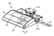
- the above described sample holders 10, 20, 30 are extremely well suited for the optical measuring device or analytical reader 50 shown in figure 3 and described in more detail in the international patent application PCT/EP2008/001468 .
- the measuring device 50 comprises a monolithic electrooptical module 52 comprising the optical and electronic parts for performing a measurement.
- This module 52 which is described in more detail in the afore-mentioned PCT/EP2008/001468 , is designed according to confocal principles rather than an off-axis geometry.
- the confocal optics of the device makes it unsensitive to mechanical unevenness of a sample and secures highest signal and lowest background intrinsic features of confocal design.
- the reader 50 comprises a slot 54 for receiving a sample holder 56 which could correspond to anyone of the above described sample holders 10, 20, 30.
- the sample holder 56 can be inserted into the slot 54 and can be moved relatively to the module 52. Additionally, the module 52 can be moved relatively to the sample holder 56.
- the reader 50 is provided with a key pad 58 for controlling the measurement and a display 60 for showing the obtained results of the measurements.
- the reader 50 can measure the color intensity or the fluorescence intensity or chemiluminescence intensity by absorption, reflectrometry, luminometry or fluorescence measurements, or other signals, such as electrochemical signals.
- the sensor and the sample slide are embedded in the reader, which is a stand alone device including housing, industrial design, electronics, optics, all necessary mechanical parts, display, memory, batteries, connectivity to USB port, printer, barcode reader, and optional wireless data transfer. It has a firmware for device control and data interpretation. Calibration curves can be saved in the internal memory.
- the reader 50 can be connected and be operated as well through an external computer.
- the sample holder (slide) can be inserted into the reader by a drawer like carriage and the filling of the holes can occur directly on the sample holder placed in this cartridge. Once the sample holder slides into the reader the reader scans the samples stepwise or on the fly. Results are directly displayed on the display 60 of the reader and/or on an external monitor of a PC connected to the reader 50 for processing and analyzing the results.
- Reagents to minimize or avoid evaporation of sample can be hygroscopic compounds such as, polyethylenglycols, diethylenglycol, glycerin, MgCl2, LiCl, CaCl2, Ca(N03)2, ZnCl2, and other organic and inorganic compounds such as alcohols and amines and the like.
- the device allows for a determination of that point in time when the first simple is applied (opening the carriage and start of the time measurement). Thereafter the samples (one or more) are applied. Finally the carriage carrying the samples is closed (end of the time measurement).
- the total time required for handling of the samples with a pipette can be determined and the time delay can be extrapolated from the first to the last sample.
- the respective samples will not occupy the whole respective spaces provided by the holes 15, 25, 30.
- the liquid (sample plus reagent mixture) in a given hole forms a meniscus, wherein the vertical thickness of the liquid generally is larger towards the walls of the holes than in the middle thereof (due to the capillary forces and the surface tension in this area).
- the shape of the meniscus (such as determined by the ratio of the peak intensity in the middle of a hole compared to the peak intensity at the wall thereof) can be used to determine the volume of the liquid.
- the determination of the volume of the sample and reagent mixture of a given hole can be used to take into account the effects of evaporation by determining the surface area of the evaporating liquid (i.e. sample and reagent mixture).
- Figure 4a shows exemplary meniscuses measured after 10 min of evaporation for the following example: Protein determination using Fluoroprofile assay (Sigma-Aldrich). Hole diameter: 1mm, volume: 1 ⁇ l; values in ⁇ g/ml, sensor focal length: 6mm, Excitation/Emission 470nm/625nm. Meniscus appears as "double peak".
- the signals at A, B, C, D, E, and F correspond to a blank, 100 ⁇ g/ml, 25 ⁇ g/ml, 6 ⁇ g/ml, 1 ⁇ g/ml and an empty hole, respectively.
- the person skilled in the art will appreciate that in order to resolve the double peak structure caused by a meniscus the resolution of the optical reader has to smaller than the hole diameter.
- Figure 4b shows the results of a protein determination using a Fluoroprofile assay (Sigma-Aldrich). Hole diameter: 1mm, volume: 1 ⁇ l; values in ⁇ g/ml, sensor focal length: 6mm, Excitation/Emission 470nm/625nm.
- the signals at A, B, C, D, E, and F correspond to a blank, 100 ⁇ g/ml, 25 ⁇ g/ml, 6 ⁇ g/ml, 1 ⁇ g/ml and an empty hole, respectively.
- Figures 4c shows the results of a DNA quantification using Quant-iT PicoGreen ds DNA Assay Kit. Volume 1 ⁇ l, sensor focal length: 6mm, Excitation/Emission 470nm/520nm.
- the signals at A, B, C, D, E, and F correspond to 50 ⁇ g/ml, 5 ⁇ g/ml, 0,5 ⁇ g/ml, 50 ⁇ g/ml, and 5 ⁇ g/ml, respectively.
- Figure 4d shows a close-up view of a portion of figure 4c .
- the described sample holders provide for the following advantage: minimized or no background of the sample holder influences the result; multiple samples can be measured at a time; easy handling and mixing of reagents in the holes possible; easy bubble free filling of holes; low costs for customer and manufacturer; disposable sample holder (slide with holes) as consumable; no contamination of analytical reader, no cleaning necessary; small sample volume; high sensitivity; evaporation of sample volume minimized by additional ingredients of the reagent mix; measurement possible within prolonged time period; sample can be reused if desired; no positioning error of sample; wide range of sample viscosity/composition possible; minimal optical crosstalk from hole to hole; sample remains in hole even if the slide is dropped; droplet geometry to a large degree does not depend on surface tension/viscosity of the sample (sample does not float on surface).
Landscapes
- Chemical & Material Sciences (AREA)
- Health & Medical Sciences (AREA)
- Analytical Chemistry (AREA)
- Physics & Mathematics (AREA)
- General Health & Medical Sciences (AREA)
- General Physics & Mathematics (AREA)
- Hematology (AREA)
- Clinical Laboratory Science (AREA)
- Chemical Kinetics & Catalysis (AREA)
- Pathology (AREA)
- Biochemistry (AREA)
- Immunology (AREA)
- Life Sciences & Earth Sciences (AREA)
- Optics & Photonics (AREA)
- Optical Measuring Cells (AREA)
- Apparatus Associated With Microorganisms And Enzymes (AREA)
- Automatic Analysis And Handling Materials Therefor (AREA)
- Devices For Use In Laboratory Experiments (AREA)
- Investigating, Analyzing Materials By Fluorescence Or Luminescence (AREA)
- Sampling And Sample Adjustment (AREA)
- Investigating Or Analysing Biological Materials (AREA)
Claims (12)
- Porte-échantillon (30) destiné à l'utilisation dans un dispositif de lecture analytique (50), tel qu'un dispositif de lecture optique ou électrochimique, le porte-échantillon (30) comprenant : un support présentant au moins un trou (35) de forme circulaire destiné à recevoir un échantillon à analyser, dans lequel le au moins un trou (35) s'étend complètement à travers le support et présente est dimensionnée de telle sorte que l'échantillon est maintenu dans le au moins un trou (35) au moyen de la tension de surface de l'échantillon, agissant entre une surface intérieure du support définissant le trou, et l'échantillon, où le support comprend un premier support supérieur (32) et un deuxième support inférieur (36) qui ensemble incorporent une membrane poreuse (34), les trous du premier support et les trous du deuxième support, qui correspondent en termes de forme, de dimensions et de disposition aux trous du deuxième support, définissent ensemble le au moins un trou (35) s'étendant complètement à travers le support, la membrane poreuse (34) étant située entre les supports, caractérisé en ce que le porte-échantillon (30) comprend en outre une première membrane (31) reliée à un côté supérieur du premier support supérieur (32) et une deuxième membrane (37) reliée à un côté inférieur du deuxième support inférieur (36) afin de recouvrir le trou (35) sur les côtés supérieur et/ou inférieur du porte-échantillon, où le porte-échantillon est conçu de telle sorte que le trou peut être rempli en immergeant le porte-échantillon dans un liquide.
- Porte-échantillon (30) selon la revendication 1, dans lequel la membrane poreuse (34) et/ou la première membrane (31) et/ou la deuxième membrane (37) sont composées d'un matériau hydrophile ou d'un matériau hydrophobe.
- Porte-échantillon (30) selon l'une quelconque des revendications 1 à 2, dans lequel le support est composé de verre, de plastique ou de métal et/ou d'un matériau présentant des propriétés optiques bien définies, tel que le rubis, la fluorine, la turquoise, l'ambre, le saphir, le zircon, de sorte que le porte-échantillon (30) peut être utilisé en tant qu'étalon optique pour des mesurages de l'échantillon dans le au moins un trou (35).
- Porte-échantillon (30) selon l'une quelconque des revendications 1 à 3, dans lequel la surface intérieure du support définissant le au moins un trou (35) est une surface hydrophile, de préférence obtenue en la recouvrant par un matériau hydrophile.
- Porte-échantillon (30) selon l'une quelconque des revendications 1 à 3, dans lequel la surface intérieure du support définissant le au moins un trou (35) est une surface hydrophobe, de préférence obtenue en la recouvrant par un matériau hydrophobe.
- Porte-échantillon (30) selon l'une quelconque des revendications 1 à 5, où le porte-échantillon (30) comprend une pluralité de trous (35), où une partie de la pluralité de trous (35) présente un diamètre supérieur au diamètre d'une autre partie de la pluralité de trous (35).
- Porte-échantillon (30) selon l'une quelconque des revendications 1 à 5, dans lequel le au moins un trou (35) présente un diamètre compris dans la plage allant de 0,1 à 10 mm.
- Porte-échantillon (30) selon la revendication 7, dans lequel le au moins un trou (35) présente un diamètre compris dans la plage allant de 0,5 à 3,0 mm.
- Procédé d'utilisation d'un porte-échantillon (30) selon l'une quelconque des revendications 1 à 8 dans un dispositif de lecture analytique (50), comprenant les étapes :de remplissage du au moins un trou (35) du porte-échantillon (30) avec un mélange d'échantillon et de réactif ;d'insertion du porte-échantillon (30) dans le dispositif de lecture analytique (50) ; etd'analyse du mélange d'échantillon et de réactif dans le au moins un trou (35) du porte-échantillon (30) au moyen du dispositif de lecture analytique (50).
- Procédé selon la revendication 9, comprenant l'étape supplémentaire d'ajout d'un agent anti-évaporation au au moins un trou (35) sélectionné à partir du groupe suivant destiné à réduire au minimum ou à éviter une évaporation de l'échantillon disposé dans le au moins un trou (15 ; 25 ; 35) du porte-échantillon (10, 20, 30), le groupe étant composé de polyéthylèneglycol, de diéthylèneglycol, de glycérine, de MgCl2, de LiCI, de CaCI2, de Ca(N03)2, de ZnCI2, et d'autres composés organiques et inorganiques, tels que des alcools et des amines.
- Procédé selon la revendication 9, dans lequel l'étape d'analyse du mélange d'échantillon et de réactif dans le au moins un trou (15 ; 25 ; 35) du porte-échantillon (10, 20, 30) au moyen du dispositif de lecture analytique (50) prend en compte les effets d'une évaporation en utilisant des étalonnages et/ou des modèles pour l'évaporation.
- Procédé selon la revendication 11, dans lequel l'étape d'analyse du mélange d'échantillon et de réactif dans le au moins un trou (15 ; 25 ; 35) du porte-échantillon (10, 20, 30) comprend en outre une détermination du volume du mélange d'échantillon et de réactif dans le au moins un trou (15 ; 25 ; 35) de sorte que le volume peut être utilisé afin de prendre en compte les effets d'une évaporation.
Priority Applications (1)
| Application Number | Priority Date | Filing Date | Title |
|---|---|---|---|
| EP09727143.1A EP2268402B1 (fr) | 2008-03-31 | 2009-03-31 | Porte-échantillon et son procédé d'utilisation |
Applications Claiming Priority (3)
| Application Number | Priority Date | Filing Date | Title |
|---|---|---|---|
| EP08006294 | 2008-03-31 | ||
| PCT/EP2009/002333 WO2009121556A1 (fr) | 2008-03-31 | 2009-03-31 | Porte-éprouvette et son procédé d'utilisation |
| EP09727143.1A EP2268402B1 (fr) | 2008-03-31 | 2009-03-31 | Porte-échantillon et son procédé d'utilisation |
Publications (2)
| Publication Number | Publication Date |
|---|---|
| EP2268402A1 EP2268402A1 (fr) | 2011-01-05 |
| EP2268402B1 true EP2268402B1 (fr) | 2013-06-19 |
Family
ID=40637749
Family Applications (1)
| Application Number | Title | Priority Date | Filing Date |
|---|---|---|---|
| EP09727143.1A Not-in-force EP2268402B1 (fr) | 2008-03-31 | 2009-03-31 | Porte-échantillon et son procédé d'utilisation |
Country Status (8)
| Country | Link |
|---|---|
| US (1) | US8563326B2 (fr) |
| EP (1) | EP2268402B1 (fr) |
| JP (1) | JP5300969B2 (fr) |
| KR (1) | KR101605575B1 (fr) |
| CN (1) | CN102026723B (fr) |
| AU (1) | AU2009231191B2 (fr) |
| CA (1) | CA2719877C (fr) |
| WO (1) | WO2009121556A1 (fr) |
Families Citing this family (19)
| Publication number | Priority date | Publication date | Assignee | Title |
|---|---|---|---|---|
| JP4229075B2 (ja) * | 2005-03-07 | 2009-02-25 | セイコーエプソン株式会社 | 有機エレクトロルミネッセンス装置及び電子機器 |
| EP2395346A3 (fr) * | 2008-04-17 | 2013-10-16 | QIAGEN Lake Constance GmbH | Norme de fluorescence et son utilisation |
| JP5731516B2 (ja) * | 2009-10-15 | 2015-06-10 | ポステック アカデミー−インダストリー ファンデーション | キュベット |
| GB2480596A (en) * | 2010-01-29 | 2011-11-30 | Kenneth John Cunningham | Disposable light scattering cuvette for liquid sample held by surface tension |
| GB201014805D0 (en) * | 2010-09-07 | 2010-10-20 | Multi Sense Technologies Ltd | Microfluidics based assay device |
| US20120261256A1 (en) * | 2011-04-13 | 2012-10-18 | Chang Chia-Pin | Sample holders and analytical instrument for point-of-care qualification of clinical samples |
| US9625465B2 (en) | 2012-05-15 | 2017-04-18 | Defined Diagnostics, Llc | Clinical diagnostic systems |
| US9213043B2 (en) | 2012-05-15 | 2015-12-15 | Wellstat Diagnostics, Llc | Clinical diagnostic system including instrument and cartridge |
| US9075042B2 (en) | 2012-05-15 | 2015-07-07 | Wellstat Diagnostics, Llc | Diagnostic systems and cartridges |
| US20140199758A1 (en) * | 2013-01-15 | 2014-07-17 | Aviv Biomedical, Inc. | Bilirubin hematolfluorometer and reagent kit |
| US20140329300A1 (en) * | 2013-05-01 | 2014-11-06 | Rarecyte, Inc. | Device for analyzing a sample and method of using the same |
| JP6185864B2 (ja) * | 2013-06-07 | 2017-08-23 | 本田技研工業株式会社 | 積分球 |
| US20170080426A1 (en) * | 2014-05-14 | 2017-03-23 | University Of Limerick | Device and method for testing compounds on living cells |
| WO2016138427A1 (fr) | 2015-02-27 | 2016-09-01 | Indx Lifecare, Inc. | Système de détection à guide d'ondes à source de lumière à balayage |
| CN108431664B (zh) * | 2015-12-23 | 2021-11-02 | 皇家飞利浦有限公司 | 荧光校准载片 |
| GB201611442D0 (en) | 2016-06-30 | 2016-08-17 | Lumiradx Tech Ltd | Fluid control |
| US11346850B2 (en) * | 2017-06-21 | 2022-05-31 | Gyntools Ltd | Assay system including assay apparatus and handheld single use assay devices for use therewith |
| AU2018374628A1 (en) * | 2017-12-01 | 2020-07-02 | Copan Italia S.P.A. | Support for the preservation of biological samples and correlated method of production |
| DE102023203424A1 (de) * | 2023-04-17 | 2024-10-17 | Robert Bosch Gesellschaft mit beschränkter Haftung | Mikrofluidische Vorrichtung, Verfahren zum Herstellen einer mikrofluidischen Vorrichtung und Verfahren zum Betreiben einer mikrofluidischen Vorrichtung |
Citations (1)
| Publication number | Priority date | Publication date | Assignee | Title |
|---|---|---|---|---|
| US20040053422A1 (en) * | 2002-09-17 | 2004-03-18 | Selena Chan | Microfluidic devices with porous membranes for molecular sieving, metering, and separations |
Family Cites Families (11)
| Publication number | Priority date | Publication date | Assignee | Title |
|---|---|---|---|---|
| US4682890A (en) | 1985-05-31 | 1987-07-28 | Health Research, Incorporated | Microsample holder and carrier therefor |
| US5284753A (en) * | 1991-03-20 | 1994-02-08 | Neuro Probe, Inc. | Multiple-site chemotactic test apparatus and method |
| US5290705A (en) * | 1992-01-13 | 1994-03-01 | R. E. Davis Chemical Corporation | Speciman support for optical analysis |
| US5314825A (en) | 1992-07-16 | 1994-05-24 | Schiapparelli Biosystems, Inc. | Chemical analyzer |
| JPH0694731A (ja) | 1992-09-11 | 1994-04-08 | Hitachi Ltd | 自動化学分析装置用検体蒸発監視装置 |
| US6893877B2 (en) | 1998-01-12 | 2005-05-17 | Massachusetts Institute Of Technology | Methods for screening substances in a microwell array |
| ATE477850T1 (de) | 1998-01-12 | 2010-09-15 | Massachusetts Inst Technology | Vorrichtung zur mikrotestdurchführung |
| WO2001061054A2 (fr) | 2000-02-18 | 2001-08-23 | Board Of Trustees Of The Leland Stanford Junior University | Appareils et procedes de conduite en parallele de reactions sur des microvolumes |
| JP4361271B2 (ja) * | 2000-10-10 | 2009-11-11 | バイオトローブ・インコーポレイテツド | アッセイ、合成、および保存用の器具、ならびに、その作製、使用、および操作の方法 |
| US20060094108A1 (en) | 2002-12-20 | 2006-05-04 | Karl Yoder | Thermal cycler for microfluidic array assays |
| JP2006322841A (ja) * | 2005-05-19 | 2006-11-30 | Shimadzu Corp | 分光測定方法及び分光光度計 |
-
2009
- 2009-03-31 CN CN200980111637.5A patent/CN102026723B/zh not_active Expired - Fee Related
- 2009-03-31 WO PCT/EP2009/002333 patent/WO2009121556A1/fr not_active Ceased
- 2009-03-31 AU AU2009231191A patent/AU2009231191B2/en not_active Ceased
- 2009-03-31 KR KR1020107024427A patent/KR101605575B1/ko not_active Expired - Fee Related
- 2009-03-31 US US12/933,832 patent/US8563326B2/en not_active Expired - Fee Related
- 2009-03-31 EP EP09727143.1A patent/EP2268402B1/fr not_active Not-in-force
- 2009-03-31 CA CA2719877A patent/CA2719877C/fr not_active Expired - Fee Related
- 2009-03-31 JP JP2011502280A patent/JP5300969B2/ja not_active Expired - Fee Related
Patent Citations (1)
| Publication number | Priority date | Publication date | Assignee | Title |
|---|---|---|---|---|
| US20040053422A1 (en) * | 2002-09-17 | 2004-03-18 | Selena Chan | Microfluidic devices with porous membranes for molecular sieving, metering, and separations |
Also Published As
| Publication number | Publication date |
|---|---|
| EP2268402A1 (fr) | 2011-01-05 |
| JP2011519416A (ja) | 2011-07-07 |
| CN102026723B (zh) | 2015-03-25 |
| CN102026723A (zh) | 2011-04-20 |
| US20110067489A1 (en) | 2011-03-24 |
| AU2009231191A1 (en) | 2009-10-08 |
| JP5300969B2 (ja) | 2013-09-25 |
| AU2009231191B2 (en) | 2014-05-15 |
| KR20100132538A (ko) | 2010-12-17 |
| KR101605575B1 (ko) | 2016-03-22 |
| CA2719877A1 (fr) | 2009-10-08 |
| CA2719877C (fr) | 2016-08-09 |
| WO2009121556A1 (fr) | 2009-10-08 |
| US8563326B2 (en) | 2013-10-22 |
Similar Documents
| Publication | Publication Date | Title |
|---|---|---|
| EP2268402B1 (fr) | Porte-échantillon et son procédé d'utilisation | |
| US8420025B2 (en) | Methods and systems for delivery of fluidic samples to sensor arrays | |
| US8486715B2 (en) | Dispensing of a diagnostic liquid onto a diagnostic reagent | |
| EP3148700B1 (fr) | Système de microplaque à colonne unique et porteur pour analyse d'échantillons biologiques | |
| US20090181463A1 (en) | Device and method for chemical, biochemical, biological and physical analysis, re-action, assay and more | |
| EP1385006A2 (fr) | Système et cartouche pour traiter un échantillon biologique | |
| JP4308732B2 (ja) | マイクロ流体滴定装置 | |
| CN102460127A (zh) | 用于识别和定量分析被分析物,特别是真菌毒素的装置和方法 | |
| US20040248306A1 (en) | Microfluidic water analytical device | |
| JP5461389B2 (ja) | 試薬表面への診断液のピエゾ計量分配 | |
| KR20230009244A (ko) | Pcr 모듈 | |
| Kanigan et al. | Living chips for drug discovery | |
| US20150253239A1 (en) | Microplate for high performance spectroscopic applications | |
| WO2009048827A1 (fr) | Micro-distributeur et lecteur intégrés | |
| EP4429821A1 (fr) | Appareil de plaque de puits et son procédé de remplissage | |
| Rile | International Bureau |
Legal Events
| Date | Code | Title | Description |
|---|---|---|---|
| PUAI | Public reference made under article 153(3) epc to a published international application that has entered the european phase |
Free format text: ORIGINAL CODE: 0009012 |
|
| 17P | Request for examination filed |
Effective date: 20100906 |
|
| AK | Designated contracting states |
Kind code of ref document: A1 Designated state(s): AT BE BG CH CY CZ DE DK EE ES FI FR GB GR HR HU IE IS IT LI LT LU LV MC MK MT NL NO PL PT RO SE SI SK TR |
|
| AX | Request for extension of the european patent |
Extension state: AL BA RS |
|
| RIN1 | Information on inventor provided before grant (corrected) |
Inventor name: FAULSTICH, KONRAD Inventor name: HABERSTROH, KLAUS |
|
| DAX | Request for extension of the european patent (deleted) | ||
| 17Q | First examination report despatched |
Effective date: 20111114 |
|
| REG | Reference to a national code |
Ref country code: DE Ref legal event code: R079 Ref document number: 602009016528 Country of ref document: DE Free format text: PREVIOUS MAIN CLASS: B01L0003000000 Ipc: G02B0021340000 |
|
| GRAJ | Information related to disapproval of communication of intention to grant by the applicant or resumption of examination proceedings by the epo deleted |
Free format text: ORIGINAL CODE: EPIDOSDIGR1 |
|
| RIC1 | Information provided on ipc code assigned before grant |
Ipc: G01N 21/03 20060101ALI20121206BHEP Ipc: B01L 3/00 20060101ALI20121206BHEP Ipc: G02B 21/34 20060101AFI20121206BHEP |
|
| GRAP | Despatch of communication of intention to grant a patent |
Free format text: ORIGINAL CODE: EPIDOSNIGR1 |
|
| GRAS | Grant fee paid |
Free format text: ORIGINAL CODE: EPIDOSNIGR3 |
|
| GRAA | (expected) grant |
Free format text: ORIGINAL CODE: 0009210 |
|
| AK | Designated contracting states |
Kind code of ref document: B1 Designated state(s): AT BE BG CH CY CZ DE DK EE ES FI FR GB GR HR HU IE IS IT LI LT LU LV MC MK MT NL NO PL PT RO SE SI SK TR |
|
| REG | Reference to a national code |
Ref country code: GB Ref legal event code: FG4D |
|
| REG | Reference to a national code |
Ref country code: CH Ref legal event code: EP |
|
| REG | Reference to a national code |
Ref country code: AT Ref legal event code: REF Ref document number: 617962 Country of ref document: AT Kind code of ref document: T Effective date: 20130715 |
|
| REG | Reference to a national code |
Ref country code: IE Ref legal event code: FG4D |
|
| REG | Reference to a national code |
Ref country code: DE Ref legal event code: R096 Ref document number: 602009016528 Country of ref document: DE Effective date: 20130814 |
|
| PG25 | Lapsed in a contracting state [announced via postgrant information from national office to epo] |
Ref country code: SI Free format text: LAPSE BECAUSE OF FAILURE TO SUBMIT A TRANSLATION OF THE DESCRIPTION OR TO PAY THE FEE WITHIN THE PRESCRIBED TIME-LIMIT Effective date: 20130619 Ref country code: GR Free format text: LAPSE BECAUSE OF FAILURE TO SUBMIT A TRANSLATION OF THE DESCRIPTION OR TO PAY THE FEE WITHIN THE PRESCRIBED TIME-LIMIT Effective date: 20130920 Ref country code: FI Free format text: LAPSE BECAUSE OF FAILURE TO SUBMIT A TRANSLATION OF THE DESCRIPTION OR TO PAY THE FEE WITHIN THE PRESCRIBED TIME-LIMIT Effective date: 20130619 Ref country code: LT Free format text: LAPSE BECAUSE OF FAILURE TO SUBMIT A TRANSLATION OF THE DESCRIPTION OR TO PAY THE FEE WITHIN THE PRESCRIBED TIME-LIMIT Effective date: 20130619 Ref country code: SE Free format text: LAPSE BECAUSE OF FAILURE TO SUBMIT A TRANSLATION OF THE DESCRIPTION OR TO PAY THE FEE WITHIN THE PRESCRIBED TIME-LIMIT Effective date: 20130619 Ref country code: NO Free format text: LAPSE BECAUSE OF FAILURE TO SUBMIT A TRANSLATION OF THE DESCRIPTION OR TO PAY THE FEE WITHIN THE PRESCRIBED TIME-LIMIT Effective date: 20130919 Ref country code: ES Free format text: LAPSE BECAUSE OF FAILURE TO SUBMIT A TRANSLATION OF THE DESCRIPTION OR TO PAY THE FEE WITHIN THE PRESCRIBED TIME-LIMIT Effective date: 20130930 |
|
| REG | Reference to a national code |
Ref country code: AT Ref legal event code: MK05 Ref document number: 617962 Country of ref document: AT Kind code of ref document: T Effective date: 20130619 |
|
| REG | Reference to a national code |
Ref country code: LT Ref legal event code: MG4D |
|
| PG25 | Lapsed in a contracting state [announced via postgrant information from national office to epo] |
Ref country code: HR Free format text: LAPSE BECAUSE OF FAILURE TO SUBMIT A TRANSLATION OF THE DESCRIPTION OR TO PAY THE FEE WITHIN THE PRESCRIBED TIME-LIMIT Effective date: 20130619 Ref country code: BG Free format text: LAPSE BECAUSE OF FAILURE TO SUBMIT A TRANSLATION OF THE DESCRIPTION OR TO PAY THE FEE WITHIN THE PRESCRIBED TIME-LIMIT Effective date: 20130919 |
|
| REG | Reference to a national code |
Ref country code: NL Ref legal event code: VDEP Effective date: 20130619 |
|
| PG25 | Lapsed in a contracting state [announced via postgrant information from national office to epo] |
Ref country code: LV Free format text: LAPSE BECAUSE OF FAILURE TO SUBMIT A TRANSLATION OF THE DESCRIPTION OR TO PAY THE FEE WITHIN THE PRESCRIBED TIME-LIMIT Effective date: 20130619 |
|
| PG25 | Lapsed in a contracting state [announced via postgrant information from national office to epo] |
Ref country code: CY Free format text: LAPSE BECAUSE OF FAILURE TO SUBMIT A TRANSLATION OF THE DESCRIPTION OR TO PAY THE FEE WITHIN THE PRESCRIBED TIME-LIMIT Effective date: 20130918 Ref country code: EE Free format text: LAPSE BECAUSE OF FAILURE TO SUBMIT A TRANSLATION OF THE DESCRIPTION OR TO PAY THE FEE WITHIN THE PRESCRIBED TIME-LIMIT Effective date: 20130619 Ref country code: SK Free format text: LAPSE BECAUSE OF FAILURE TO SUBMIT A TRANSLATION OF THE DESCRIPTION OR TO PAY THE FEE WITHIN THE PRESCRIBED TIME-LIMIT Effective date: 20130619 Ref country code: PT Free format text: LAPSE BECAUSE OF FAILURE TO SUBMIT A TRANSLATION OF THE DESCRIPTION OR TO PAY THE FEE WITHIN THE PRESCRIBED TIME-LIMIT Effective date: 20131021 Ref country code: CZ Free format text: LAPSE BECAUSE OF FAILURE TO SUBMIT A TRANSLATION OF THE DESCRIPTION OR TO PAY THE FEE WITHIN THE PRESCRIBED TIME-LIMIT Effective date: 20130619 Ref country code: IS Free format text: LAPSE BECAUSE OF FAILURE TO SUBMIT A TRANSLATION OF THE DESCRIPTION OR TO PAY THE FEE WITHIN THE PRESCRIBED TIME-LIMIT Effective date: 20131019 Ref country code: BE Free format text: LAPSE BECAUSE OF FAILURE TO SUBMIT A TRANSLATION OF THE DESCRIPTION OR TO PAY THE FEE WITHIN THE PRESCRIBED TIME-LIMIT Effective date: 20130619 Ref country code: AT Free format text: LAPSE BECAUSE OF FAILURE TO SUBMIT A TRANSLATION OF THE DESCRIPTION OR TO PAY THE FEE WITHIN THE PRESCRIBED TIME-LIMIT Effective date: 20130619 |
|
| PG25 | Lapsed in a contracting state [announced via postgrant information from national office to epo] |
Ref country code: PL Free format text: LAPSE BECAUSE OF FAILURE TO SUBMIT A TRANSLATION OF THE DESCRIPTION OR TO PAY THE FEE WITHIN THE PRESCRIBED TIME-LIMIT Effective date: 20130619 Ref country code: RO Free format text: LAPSE BECAUSE OF FAILURE TO SUBMIT A TRANSLATION OF THE DESCRIPTION OR TO PAY THE FEE WITHIN THE PRESCRIBED TIME-LIMIT Effective date: 20130619 Ref country code: NL Free format text: LAPSE BECAUSE OF FAILURE TO SUBMIT A TRANSLATION OF THE DESCRIPTION OR TO PAY THE FEE WITHIN THE PRESCRIBED TIME-LIMIT Effective date: 20130619 |
|
| PG25 | Lapsed in a contracting state [announced via postgrant information from national office to epo] |
Ref country code: CY Free format text: LAPSE BECAUSE OF FAILURE TO SUBMIT A TRANSLATION OF THE DESCRIPTION OR TO PAY THE FEE WITHIN THE PRESCRIBED TIME-LIMIT Effective date: 20130619 |
|
| PLBE | No opposition filed within time limit |
Free format text: ORIGINAL CODE: 0009261 |
|
| STAA | Information on the status of an ep patent application or granted ep patent |
Free format text: STATUS: NO OPPOSITION FILED WITHIN TIME LIMIT |
|
| PG25 | Lapsed in a contracting state [announced via postgrant information from national office to epo] |
Ref country code: DK Free format text: LAPSE BECAUSE OF FAILURE TO SUBMIT A TRANSLATION OF THE DESCRIPTION OR TO PAY THE FEE WITHIN THE PRESCRIBED TIME-LIMIT Effective date: 20130619 |
|
| 26N | No opposition filed |
Effective date: 20140320 |
|
| PG25 | Lapsed in a contracting state [announced via postgrant information from national office to epo] |
Ref country code: IT Free format text: LAPSE BECAUSE OF FAILURE TO SUBMIT A TRANSLATION OF THE DESCRIPTION OR TO PAY THE FEE WITHIN THE PRESCRIBED TIME-LIMIT Effective date: 20130619 |
|
| REG | Reference to a national code |
Ref country code: DE Ref legal event code: R097 Ref document number: 602009016528 Country of ref document: DE Effective date: 20140320 |
|
| PG25 | Lapsed in a contracting state [announced via postgrant information from national office to epo] |
Ref country code: LU Free format text: LAPSE BECAUSE OF FAILURE TO SUBMIT A TRANSLATION OF THE DESCRIPTION OR TO PAY THE FEE WITHIN THE PRESCRIBED TIME-LIMIT Effective date: 20140331 |
|
| REG | Reference to a national code |
Ref country code: IE Ref legal event code: MM4A |
|
| PG25 | Lapsed in a contracting state [announced via postgrant information from national office to epo] |
Ref country code: IE Free format text: LAPSE BECAUSE OF NON-PAYMENT OF DUE FEES Effective date: 20140331 |
|
| PG25 | Lapsed in a contracting state [announced via postgrant information from national office to epo] |
Ref country code: MT Free format text: LAPSE BECAUSE OF FAILURE TO SUBMIT A TRANSLATION OF THE DESCRIPTION OR TO PAY THE FEE WITHIN THE PRESCRIBED TIME-LIMIT Effective date: 20130619 |
|
| REG | Reference to a national code |
Ref country code: FR Ref legal event code: PLFP Year of fee payment: 8 |
|
| PGFP | Annual fee paid to national office [announced via postgrant information from national office to epo] |
Ref country code: DE Payment date: 20160321 Year of fee payment: 8 Ref country code: CH Payment date: 20160323 Year of fee payment: 8 |
|
| PG25 | Lapsed in a contracting state [announced via postgrant information from national office to epo] |
Ref country code: MC Free format text: LAPSE BECAUSE OF FAILURE TO SUBMIT A TRANSLATION OF THE DESCRIPTION OR TO PAY THE FEE WITHIN THE PRESCRIBED TIME-LIMIT Effective date: 20130619 |
|
| PGFP | Annual fee paid to national office [announced via postgrant information from national office to epo] |
Ref country code: GB Payment date: 20160321 Year of fee payment: 8 Ref country code: FR Payment date: 20160321 Year of fee payment: 8 |
|
| PG25 | Lapsed in a contracting state [announced via postgrant information from national office to epo] |
Ref country code: TR Free format text: LAPSE BECAUSE OF FAILURE TO SUBMIT A TRANSLATION OF THE DESCRIPTION OR TO PAY THE FEE WITHIN THE PRESCRIBED TIME-LIMIT Effective date: 20130619 Ref country code: HU Free format text: LAPSE BECAUSE OF FAILURE TO SUBMIT A TRANSLATION OF THE DESCRIPTION OR TO PAY THE FEE WITHIN THE PRESCRIBED TIME-LIMIT; INVALID AB INITIO Effective date: 20090331 |
|
| REG | Reference to a national code |
Ref country code: DE Ref legal event code: R119 Ref document number: 602009016528 Country of ref document: DE |
|
| REG | Reference to a national code |
Ref country code: CH Ref legal event code: PL |
|
| GBPC | Gb: european patent ceased through non-payment of renewal fee |
Effective date: 20170331 |
|
| REG | Reference to a national code |
Ref country code: FR Ref legal event code: ST Effective date: 20171130 |
|
| PG25 | Lapsed in a contracting state [announced via postgrant information from national office to epo] |
Ref country code: DE Free format text: LAPSE BECAUSE OF NON-PAYMENT OF DUE FEES Effective date: 20171003 Ref country code: FR Free format text: LAPSE BECAUSE OF NON-PAYMENT OF DUE FEES Effective date: 20170331 |
|
| PG25 | Lapsed in a contracting state [announced via postgrant information from national office to epo] |
Ref country code: LI Free format text: LAPSE BECAUSE OF NON-PAYMENT OF DUE FEES Effective date: 20170331 Ref country code: GB Free format text: LAPSE BECAUSE OF NON-PAYMENT OF DUE FEES Effective date: 20170331 Ref country code: CH Free format text: LAPSE BECAUSE OF NON-PAYMENT OF DUE FEES Effective date: 20170331 |
|
| PG25 | Lapsed in a contracting state [announced via postgrant information from national office to epo] |
Ref country code: MK Free format text: LAPSE BECAUSE OF FAILURE TO SUBMIT A TRANSLATION OF THE DESCRIPTION OR TO PAY THE FEE WITHIN THE PRESCRIBED TIME-LIMIT Effective date: 20130619 |