EP2268929B1 - Dispositif de fixation de matériaux de garniture - Google Patents
Dispositif de fixation de matériaux de garniture Download PDFInfo
- Publication number
- EP2268929B1 EP2268929B1 EP09727988.9A EP09727988A EP2268929B1 EP 2268929 B1 EP2268929 B1 EP 2268929B1 EP 09727988 A EP09727988 A EP 09727988A EP 2268929 B1 EP2268929 B1 EP 2268929B1
- Authority
- EP
- European Patent Office
- Prior art keywords
- spacer
- lining material
- spacers
- wall surface
- holding device
- Prior art date
- Legal status (The legal status is an assumption and is not a legal conclusion. Google has not performed a legal analysis and makes no representation as to the accuracy of the status listed.)
- Active
Links
Images


Classifications
-
- F—MECHANICAL ENGINEERING; LIGHTING; HEATING; WEAPONS; BLASTING
- F16—ENGINEERING ELEMENTS AND UNITS; GENERAL MEASURES FOR PRODUCING AND MAINTAINING EFFECTIVE FUNCTIONING OF MACHINES OR INSTALLATIONS; THERMAL INSULATION IN GENERAL
- F16B—DEVICES FOR FASTENING OR SECURING CONSTRUCTIONAL ELEMENTS OR MACHINE PARTS TOGETHER, e.g. NAILS, BOLTS, CIRCLIPS, CLAMPS, CLIPS OR WEDGES; JOINTS OR JOINTING
- F16B5/00—Joining sheets or plates, e.g. panels, to one another or to strips or bars parallel to them
- F16B5/08—Joining sheets or plates, e.g. panels, to one another or to strips or bars parallel to them by means of welds or the like
Definitions
- the invention relates to a holding device for fixing a lining material to a wall surface, in particular a container, apparatus or plant wall, which can be fixed to the wall surface by means of spacers.
- Generic fixtures are needed, for example, for lining containers that are made of either metal or non-compatible plastic or fiberglass.
- the materials used in this case are generally not acid-resistant or impure, so that an additional acid-resistant and / or high-purity lining of the container is required.
- the lining materials provided in this case are used as interior trim everywhere, where as a result of large temperature fluctuations, a shock effect can occur by cooling the outer materials and cracks or leakage are caused.
- a lining is required where working with corrosive gases or liquid substances and the housing walls are exposed to these gases or liquids. For heat and corrosion protection of the walls, which very often have flow areas with cross sections of 100 m 2 and more, the inner areas facing the flow areas are therefore covered with anticorrosive foils made of plastic.
- plastic MFA, PFA or FEP in film form is used, because this plastic provides adequate corrosion protection and can be used at the same time for good insulation against thermal shock.
- lining films are required for high-purity containers (semiconductors) and for highly resistant containers (chemistry) as well as for columns and other apparatus (chemistry).
- lining materials preferably plastic sheets, the entire surface, wherein the lining materials are selectively held on a variety of attachment or fixed points on the wall surface of the container.
- the required mounting or fixing points are here on the inner wall of the container attached and are used for suspension, usually only a few attachment points are provided per m 2 .
- the attachment or fixed points consist according to the known prior art of metal bolts or similar metal parts, which are connected to the housing wall. For example, fastening or fixed points made of metal can be screwed, glued or welded to the housing wall.
- the use of plastic materials comes into consideration, which are usually fixed in the same way, where it depends on the material of the housing, which mounting is selected.
- Plastic materials usually have a higher chemical resistance than metallic standard solutions, so that the attachment points usually have to be subsequently additionally covered with a film when exposed unclean plastics or metal parts protrude into the interior of the container. As a result, an increased workload is required.
- the plastic films provided are supplied only in certain web widths and therefore there is a need to additionally join the lining materials along the web edges, for example by means of welds.
- non-weldable peel sheets are used, which can be manufactured in certain web widths and clamped between flange pieces.
- the length of the container walls is extremely limited and requires a variety of flange, whereby the cost increases significantly and require a lot of technical effort for the screw connection of the flange.
- WO 03/004883 A1 From the WO 03/004883 A1 is a fastener and a method for its preparation and use known.
- the fastening elements shown in the embodiments serve for fastening at least one sheet-like component at a distance from a carrier body part.
- These are screw connections, which however can not be used with plastic films due to the required tightness.
- the object of the present invention is to provide a secure attachment method for lining materials to produce a durable durable compound that withstands all corrosive attacks.
- the spacers are at least partially made of plastic and with a first contact surface with the wall surface and with a second contact surface with the lining material are welded. Further advantageous embodiments of the invention will become apparent from the dependent claims.
- plastic for the spacers avoids the problem of corrosive gas destruction due to permeation or leakage liquids, providing a high strength and durable connection by welding the spacers to the wall surface on the one hand and the lining material on the other.
- a welding is carried out with the aid of electromagnetic radiation, on the one hand, the spacers made of a plastic material and on the other hand, the wall surface or the lining material also consists of a plastic, so that in the case of sufficient compatibility, the plastics can be welded together directly.
- some of the plastic materials used are either provided with an absorbent coating or enriched with absorbent particles.
- a container was made for example of a metal or consists of a plastic material, which is not can be welded, for example, GRP
- an additional lining of the container inner walls with a plastic layer which serves on the one hand to further protect the container and on the other hand is suitable for welding with the spacers.
- the plastic lining materials used may then also be welded thereto after fixing the spacers, so that in the respective container in addition to the outer wall a second inner wall is present, which consists of the lining material and spaced from the actual container wall is arranged.
- the spacers used for this purpose are welded to a first contact surface on the one hand with the wall surface and with a second contact surface on the other hand with the lining material. If the plastic materials used are not mutually compatible, ie welded, it is also possible to provide a two-part spacer, which on the one hand is compatible with the wall surface and on the other hand compatible with the lining material, wherein a connection of the two-part design of the spacer is ensured by a suitable coupling layer.
- spacer there is in a two-part embodiment of the spacer but also the possibility that a spacer made of metal and another spacer is made of plastic and is connected by positive locking.
- the wall also made of metal and make a weld with a spacer by conventional methods, while the second spacer, usually made of plastic and thus can be welded directly to the lining material, preferably one Welding with the help of electromagnetic radiation takes place.
- the spacers themselves have a first contact surface on an end face of the spacers, which for example serves to connect the spacers to the wall.
- a second contact surface lies on a diametrically opposite end face of the spacers or a surface parallel thereto.
- the lining material can be placed on the spacers and welded to them, whereby the particular advantage is achieved that the lining material can be processed over the entire surface and without interruption and thus the risk of penetration of the lining material in the region of the spacers can be almost excluded, because the Lining material consists of a smooth surface.
- the lining materials are provided with apertures, through which the spacers can be passed, so that the lining material can be connected to the spacers on an inner surface which runs parallel to the outer end face.
- the spacer may additionally be covered with a glued or welded lining material.
- the spacers used are either round or oval or can alternatively be used as strips, which are provided on the aligned lining material for the contact surface at least in sections with an absorbent layer.
- An absorbent layer is preferably used, since they can be welded together by means of suitable electromagnetic radiation through the absorption and plasticization taking place, the lining material itself being transparent to electromagnetic radiation.
- the type and shape of the spacers depends on the local conditions, the existing container size and the tensile stresses on the lining materials, so that optionally the dimensioning of the individual spacers can be changed.
- the contact surface of the spacers aligned with the wall surface can hereby be provided at least in sections with an absorbent layer, as well as the outer contact surface, wherein preferably the outer contact surface is not provided with an absorbent layer over the entire surface, but only partially has such an absorbent layer, for example one operation from the inside of the container forth by electromagnetic radiation welding can be done both with the wall surface and with the lining material.
- the electromagnetic radiation can thus pass between the absorbent layers and reach the second contact surface which is aligned on the wall side.
- electromagnetically absorbing layers can be applied by coextrusion, for example, over the entire surface or in strip form, or at least a portion of the absorbent coating can be removed again during full-surface application by subsequent mechanical processing operations in order to achieve the required transmission of the electromagnetic radiation guarantee.
- the spacers in cross-section a U-profile, a U-profile with expiring limb ends and inner or outer contact surfaces, a T-profile, a trapezoidal profile, a V-profile with wide base surface and expiring Leg ends or, form a hat profile or consist of a preferably full-surface rectangular profile or square profile.
- Spacers can therefore be used in a variety of profile shapes used, preferably round or strip designs are used.
- a U-profile for example, allows a connection of the base to the wall surface, while the end faces of the legs can be connected to the lining material.
- the leg ends can be used for connection with the lining material, which may be located inside or outside.
- a T-profile which can be connected with its foot end to the wall surface, while the upper portion with the outside or with the parallel thereto extending inner surface can be used for connection to the lining material.
- the use is in the form of a trapezoidal profile, which is also connectable in the middle region with the wall and with the trapezoidal end with the lining material.
- the use of a V-profile comes with wide base area and expiring Legs into consideration, since the base surface is suitable for connection to the wall surface, while the tapered leg ends can be used with their flat sides for conditioning of the lining material.
- a hat profile In a simplified form, moreover, it is possible to use a full-surface rectangular profile or square profile, which is provided on the parallel outer surfaces each with at least a partially absorbent coating, which allows a weld with the wall surface and the lining material.
- the spacers electromagnetically permeable plastic materials that is usually used translucent materials.
- translucent plastics are used for the lining materials while, on the other hand, the vessel wall or container coating can be made of a plastic material absorbing electromagnetic radiation.
- the spacers are formed in two parts, wherein a first spacer part with the wall surface and a second spacer part is connected to the lining material and both spacers are interconnected by a coupling element.
- a coupling element Preferably, such a solution is used when incompatible plastic materials are used for the wall surface and the lining material.
- the respective spacers are used in the appropriate compatible form to the plastics used and interconnected by means of the coupling layer.
- the coupling layer can for example consist of an adhesive layer or it is possible to provide a positive and / or non-positive connection.
- the coupling elements consist of a compressible dovetail-shaped toothing or similar teeth, so that the two spacer parts can be pressed together, and in particular it does not insist on a compatibility of the used Plastics arrives and thus the spacers are adaptable on the one hand to the wall surface and on the other hand to the lining material.
- the coupling elements may be T-shaped, mushroom-shaped, U-shaped with expiring limbs, plate-shaped or wavy, wherein the respective coupling elements, that is, the two spacers hooked together, jammed or form-fitting be connected and welded simultaneously on the one hand with the wall surface and on the other hand with the lining material.
- a T-shaped coupling element can be received in a stepped bore of a disc and welded to the wall, while the disc is welded to the lining material, so that the two coupling elements used themselves do not have to be welded together and are held by a positive connection.
- S-shaped or angularly shaped coupling elements in question which in turn may also be round or strip-shaped, which are hooked or jammed together.
- the intended for connection wall surface may for example consist of a laminated, preferably thin plastic material which is adhered to a metal outer wall or a GRP wall.
- a metal outer wall or a GRP wall may be used.
- weld the spacers directly to the wall surface or the plastic material.
- the wall surface itself consists of a stable plastic outer wall and thus direct welding is made possible, in particular with the aid of two-part spacers, which are matched to the other plastic materials used.
- a distance between the wall surface and the lining material is created by the spacers, which can be regarded as a leakage space, for example, and thus a leak in the lining material with an outlet of a medium, which passes through a first lining material, by suitable sensors can be detected.
- the gap offers the possibility that the lining material can expand according to the prevailing temperatures and that resulting overpressures or underpressures can be compensated.
- the spacers are made of a light transparent plastic material, so that by means of electromagnetic radiation, a welding of the plastic materials or the absorbent layer with the wall surface or the lining material is made possible.
- the wall surface is preferably made of a light-absorbing plastic material or a wall surface of a plastic material is used, which is additionally provided with an absorbent coating.
- the lining material is manufactured from a light-transparent plastic material so that subsequent welding with the aid of electromagnetic radiation is made possible.
- the contact surface of the spacers may be provided with a light-absorbing layer, or a light-absorbing spacer may be used which, by its shape, ensures the irradiation of the rear contact surface to the wall surface.
- thermoplastics preferably PE, PP, PE-UHMW or partially fluorinated thermoplastics, preferably PVDF, E-CTFE or highly fluorinated thermoplastics, preferably FEP, MFA, PFA or modified PTFE, wherein the absorbent coating of the same plastic materials or consists of PE-UHMW and modified PTFE of similar plastic materials.
- the plastic materials used can have thermostable additives in the form of particles which are laser-sensitive or infrared-sensitive and consist of organic and inorganic materials having a minimum temperature stability, the temperature corresponding to the processing temperatures of the plastic materials used and wherein the additives depending on the heat exposure process, for example from colorants in the form of dyes or color pigments, such as soot particles or mica with tin-antimony coating, may exist to allow absorption of the electromagnetic radiation.
- thermostable additives absorbing in the coating are also mainly comprised of infrared-sensitive or laser-sensitive particles, preferably organic or inorganic materials having a minimum temperature stability corresponding to the processing temperatures of the plastic materials used, and depending on the heat exposure process, for example color pigments such as carbon black particles or zinc antimony coated mica consist.
- the absorbent plastic materials adhered to the wall surface.
- thermostable particles are used as in the absorbent coating.
- the plastic materials and coatings used here absorb electromagnetic radiation in the wavelength range of 150 to 2,500 nanometers, preferably 500 to 1,500 nanometers, particularly preferably 800 to 1,000 nanometers.
- the spacers may be formed in two or more parts.
- the coupling elements may have on their outer side a structured surface as an adhesion-promoting bonding layer, so that a particularly intimate bond is achieved between the coupling parts and the respective spacers, wherein a coating absorbing the electromagnetic radiation at least partially aligned in the direction of the lining material. The situation is similar if the spacer is to be connected to a wall made of plastic.
- the coupling elements are formed in two or more parts, wherein the adhesion-promoting bonding layer and at least one, the electromagnetic radiation absorbing coating one or more layers, preferably twisted, twisted or braided is applied.
- the coupling elements can adhesion-promoting additives on the outside, for example, textile structures such as woven, knitted or nonwoven fabrics of E-glass or ECR glass, C-fibers, aramid fibers, polyester or polyacrylonitrile, or other synthetic fibers or those of plastic materials, preferably with a polymeric matrix of the same or related plastics as the lining material, have.
- the coupling elements may have on their outside adhesion-promoting additives in the form of hybrid tapes, hybrid cords or hybrid yarns which consist of electromagnetic radiation absorbing or non-absorbent polymeric tapes and inorganic fiber bundles, preferably C-fibers, glass fibers, silicate fibers or aramid fibers, wherein the reinforcing fibers with Resin are glued together.
- the adhesion-promoting bonding layer is in this case usually embedded in the material of a spacer and protrudes at least partially out of the surface, so that a second spacer can be pressed onto the adhesion-promoting bonding layer after partial plasticization and, after cooling, leads to a particularly intimate bond.
- the material of the first spacer part has a higher melting temperature than the second spacer part, so that a detachment of the bonding layer due to the heating can be excluded.
- a solid-state laser for plasticizing the absorbent plastic materials or coatings, a solid-state laser, a gas laser, is used as the electromagnetic radiation source
- Semiconductor laser an infrared light source, such as a xenon short arc lamp, used or a CO 2 laser used.
- induction welding the heat required for welding is introduced into the joining zone by means of an alternating magnetic field.
- the main phases of this process are heating, consolidation under pressure and cooling, the main influencing parameters being determined by the feed rate, the consolidation pressure and the temperatures of the joining zone.
- Welding plastic materials requires a welding additive that converts the energy of an electromagnetic field into heat. This welding additive, hereinafter referred to as filler, remains permanently in the welding zone.
- the nanoparticles or the millbase can undergo thermal excitation by a magnetic field or an electric field, wherein a magnetic field causes a movement of the nanoparticles in a substance, while electric fields cause excitation of the electrons. Both measures lead to a warming of the nanoparticles or the ground material due to the resulting friction.
- a magnetic reversal of a magnetized ferromagnetic material is carried out in normal materials with many Weiss districts by the displacement of the potential barriers between the individual domains, that is, the magnetic moments can approach the boundaries of a Weiss'schen range and then belong to the adjacent domain. If the size of the particles now falls below the size of the white areas, the particle in question only consists of a white area. In such "single domain particels" a shift of a potential barrier is not possible because no wall exists between two domains and thus there is no probability for an antiparallel aligned atomic magnetic moment. That means in single domain particles, the spins can only change collectively, which is reflected in a very high coercive field strength.
- Crystallites of ferromagnetics can be thought of as being composed of domains. Within these domains or Weiss domains, the atomic magnetic moments are aligned in parallel. The volume of the Weiss areas is typically 10 -4 to 10 -6 mm 3 .
- a ferromagnetic material If a ferromagnetic material is brought into an external magnetic field, the magnetic moments of the Weiss domains are aligned parallel to the external magnetic field. There is therefore a magnetization.
- the magnetization increases with increasing field strength of the external magnetic field up to a saturation field strength at which a complete alignment of the electron spins is achieved.
- the magnetization of the sample goes back to zero. If the field strength of the external magnetic field continues to rise to a value, then the negative saturation magnetization is achieved. If you reduce the field strength again, the direction turns around and then increases it successively.
- the ferromagnetic substances may consist of, for example, a metallic millbase or nanoparticles may be used which have further positive properties.
- non-spherical particles may exhibit particle shape isotropy because it is easier to magnetize a cylindrical particle along the edge than along the short edge.
- the deviation from the spherical shape need not be particularly pronounced, so a deviation of 1.1 to 1.5% of the spherical shape already causes a fourfold increase in the coercivity field strength.
- nanoparticles which may be magnetic, ferrimagnetic, ferromagnetic, antiferromagnetic or supraparamagnetic.
- the superparamagnetism in nanoparticles is further substantiated by the decrease in the particle volume, so that the atomic magnetic moments are increasingly affected by the thermal Movement of the particles are affected and can not be aligned in parallel. It comes to superparamagnetism.
- Superparamagnetic particles behave in the same way as paramagnetic particles, but they have a much larger magnetic moment. Below a so-called block temperature, these substances behave again ferromagnetically.
- Superparamagnetic materials show no hysteresis loop, so they can be easily differentiated experimentally from ferromagnetic particles.
- the property of the nanoparticles depends, for example, on the mentioned block temperature and on the shape of the particles.
- rod-shaped magnetic nanoparticles measuring 2 ⁇ 10 nm may have a block temperature of only 110 K, but spherical particles having a diameter of 2 nm may have one of 12 K.
- the synthesis of magnetic nanoparticles faces a number of problems. In order to obtain a uniform behavior of the nanoparticles, it is of essential importance to control some parameters as precisely as possible. On the one hand, it is desirable to obtain the smallest possible size distribution of the particles, since the magnetic behavior of nanoparticles is decisively determined by their size. Standard synthesis methods can narrow the size distribution only to a deviation of about 10%. In general, however, fractions are required whose size range distribution is less than 5%. A common method is fractionated flocculation, adding a pure solvent to a sample of nanoparticles of different sizes conglomerates the largest particles because they have the largest van der Waals attractions. The conglomerate can then be separated by centrifuging and the process repeated.
- Another parameter is the crystallinity of the products. It is desirable to have a high crystallinity in order to achieve the highest possible magnetization. However, influencing the crystal structure is also an important parameter since it allows the anisotropy of the magnetic nanoparticles to be controlled. In general, both the increase in crystallinity and the influence of the crystal structure are achieved by a controlled aging process, for example by heating can reach a certain temperature over a certain period of time. For the preparation of the individual nanoparticles various methods are known, which can not be discussed in detail here.
- nanoparticles as filler with their magnetic, ferrimagnetic, ferromagnetic, antiferromagnetic or supraparamagnetic properties is particularly suitable for bonding a wide variety of plastic materials, the filler containing nanoscale, magnetic or oxidic particles, which may consist of aggregated primary particles or wherein the filler consists of ferrites, Oxides or mixed metal oxides can exist.
- the particle size is typically between 1 and 500 nm, in particular between 2 and 100 nm.
- Excitation of the nanoparticles can be carried out, for example, by microwave radiation with a frequency of 1.5 to 10 GHz, preferably in the range of 2 to 3 GHz, but other electromagnetic radiation can also be used by which the properties of the nanoparticles can also be utilized as fillers, and to a heating of the materials to be welded, preferably plastic materials leads.
- various metals can be added as ground material to the plastic materials in enriched form, so that with the aid of an electromagnetic field, taking into account the resulting by the field change movements within the enriched material to a warming and thus can be used to weld different plastic materials.
- an electromagnetic radiation should be used, which is typically in the resonance range of the nanoparticles or the ground material used in order to achieve a high energy input, whereby by targeted addition of nanoparticles, a change in the resonant frequency can take place.
- nanoparticles or regrind can be dispensed with the use of transparent plastic materials and instead, if appropriate, inexpensive plastic material with appropriate enrichment can be used.
- enrichments of nanoparticles typically 1 to 5%, preferably 2 to 3%, are sufficient in order to carry out welding by means of an induction device or microwave irradiation.
- regrind in particular finely ground metal (metal dust) is also suitable because of the dipole effect for compounds.
- a high level of safety is subsequently ensured by the microwave irradiation or induction welding due to the energy sources used.
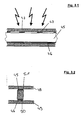
- FIG. 1 shows in a sectional side view a spacer 1, which is provided for connecting a lining material 2 with a wall surface 3.
- a spacer 1 which is provided for connecting a lining material 2 with a wall surface 3.
- possible shapes of the spacer shown in the sectional side view 1 are shown, in a first representation of a spacer 1 in a round embodiment and in the further plan view of a spacer 4 in an oval embodiment.
- the cross-sectional shape of the two different spacers 1 and 4 corresponds to the sectional side view.
- the shape of the spacers 1 or 4 used depends on the purpose of use and the possibly resulting loads from the welded lining material 2.
- the spacer 1 is U-shaped and rests with its base 5 with a first contact surface 6 directly to a wall surface 3.
- the wall surface 3 consists of a supporting wall 7, which may be made for example of metal or fiberglass and an adhesive layer 8 and a plastic layer 9, which is additionally provided to the inner lining of the container.
- the plastic materials used here, the plastic layer 9 are compatible with the plastic materials used Spacer 1, so that a direct welding can be done or as in the embodiment shown with the aid of an absorbent coating 10 by means of electromagnetic radiation 11 can be made a connection.
- the U-shaped spacer 1 has right-angled outgoing leg ends 12, 13 which are bevelled and are provided for the conditioning of the lining material 2, wherein the investment of the lining material 2 takes place on a second contact surface 14.
- the lining material 2 which is made transparent in this case, could be placed directly on the end face 15 of the spacer 1 and also welded thereto.
- the lining material 2 has an opening 17 through which the spacer 1 is guided.
- the lining material 2 abuts directly on an absorbent coating 16, which is formed below the second contact surface 14 of the spacer 1.
- the lining material 2 could be used in a light-transparent version, which is placed above the two outgoing legs 12, 13, so that also can be welded to the wall surface 3 and the spacer 1, using an absorbent interlayer, so
- the particular advantage arises that the inside of the container to be lined is coated over its entire surface with a lining material 2.
- gap 18 which, in the case of temperature fluctuations, deforms the lining material 2 both at overpressure and under reduced pressure guaranteed and can additionally be used as a leakage space in case of need so that passing through the lining material gases enter the gap 18 and are detectable via sensitive sensors and can be sucked off to avoid damage to the wall surface.
- the gap 18 can be rinsed by gases or liquids, so as to preclude damage to the wall surface 3, in particular the supporting wall 7.
- FIG. 2 shows in three sectional side views of various embodiments of spacers 20, 21, 22, which are each arranged between a lining material 23 and a wall surface 24.
- the wall surface 24 is in this case only shown as a supporting plastic layer, of course, an arrangement according to the FIG. 1 can be used.
- a pot-shaped spacer 20 which has outgoing legs 25, 26, on which an absorbent coating 27, 28 as an intermediate layer is present, in order to enable welding by means of electromagnetic radiation 29.
- the outgoing leg ends 25, 26 in this case form the second contact surface of the spacer 20, while the first contact surface of the spacer is formed by the wide base 30.
- the second embodiment of the spacer 21 consists of a solid material consisting of a trapezoidal shape, which is made of a light transparent material and in the lower region a first contact surface 31 with an absorbent coating 32 and in the upper region a second contact surface 33, each having an absorbent coating 34.
- the spacer 21 lies with the first contact surface 31 directly on the wall surface 24, or at, while the lining material 23 rests on the second contact surface 33.
- the absorbent coating 34 is present only in strips, so that a welding of the lower contact surface 31 is made possible.
- an approximately V-shaped spacer 22 is shown, which abuts with a broad base 35 as the first contact surface 36 and absorbent coating 37 on the wall surface 24, while the lining material 23 abuts the front ends on the leg ends 38, 39 of the spacer 22 , wherein between the lining material and the second contact surface 40 in turn an absorbent coating 41 is provided.
- the absorbent coatings 37, 41 serve to absorb electromagnetic radiation 29 and thereby plastify the lining material 23, spacer 22 and wall surface 24 to form a welded connection between the lining material 23 and the wall surface 24 over the Spacer 22 produce.
- the aforementioned spacers 20, 21, 22 can be used in a round or strip-shaped form.
- FIG. 3 shows a further embodiment of a spacer 45, which in this case consists of a rectangular strip having on one side a continuous absorbent coating 46, while on the upper side partial coatings 47 are provided.
- the partial coatings 47 may either be coextruded onto the spacer 45 or may be prepared by mechanical post-processing of a previously applied continuous coating.
- Such types of spacers offer where larger loads must be intercepted and a contact of the lining material 48 with the supporting wall surface 49 is required over a large contact area.
- the spacer 45 is in this case with a first contact surface 50 directly to the wall surface 49 with the interposition of an absorbent layer 46, while a second contact surface 51 is provided for conditioning the lining material 48.
- the attachment of the lining material 48 using the spacer 45 may in this case be carried out in one or in two operations.
- the partial coating 47 for example, the lining material can be welded directly to the wall surface 49 via the spacer 45, so that only one operation is required.
- both alternative options can be applied.
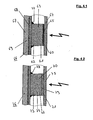
- FIG. 4 shows two further embodiments of a spacer 60, 70, which consists in the upper representation of two spacers 61, 62 and are connected to each other via a coupling layer 63.
- the rest of the construction largely corresponds to the previous embodiments, wherein a lining material 64 on the spacer 60 with the interposition of an absorbent coating 65 is applied, which is provided for welding the lining material 64 with the first part 61 of the spacer 60.
- the wall surface 66 shown consists of a supporting wall 67, which can be made of metal or GRP, for example, and an adhesive layer 68 and an inner plastic layer 69 which is provided for further connection with the spacer 62 of the spacer 60.
- this spacer 60 is that different plastic materials can be used for the lining material 64 and the inner plastic layer 69, which are normally not connectable to each other or via a one-piece spacer. For this reason, a two-part embodiment of the spacer 60 is chosen, wherein the first spacer 61 is compatible with the lining material 64 with respect to the plastic material used and can be welded by means of the absorbent coating 65, while the second spacer 62 is made of a plastic, which in turn is compatible with the material of the inner plastic layer 69.
- the exemplary embodiment shown shows a weld seam 77 for fastening the spacer 62 to the inner plastic layer 69.
- the second spacer 62 is designed to be compatible with the plastic layer 69 can therefore be used, for example, by hot gas pull welding.
- an absorption layer is a weld for which the lining material 64 and the spacer 60 are made of light transparent materials.
- adapter parts made of plastic can also be connected by mirroring with the wall surface.
- a heating of the wall surface and the adapter part is made with the help of a heated disc, a bar or a knife and removed after reaching the necessary temperature, the aid for heating and made a simultaneous welding of the adapter part a welded joint. This operation can optionally be done fully automatically with a device.
- the lower sectioned side view of FIG. 4 shows a similar construction of a spacer 70, which consists in the present case on the inner side of the two spacers 71, 72 and on the outer side of a further spacer member 73, wherein the two spacers 72 and 73 via a coupling layer 74 with each other are connected.
- the connection of the spacer 70 with the lining material 75 or the wall surface 76 can take place in the manner described above, wherein achieved by the two-part variant of the spacer 70 with the spacer parts 71, 72 on the lining material 75 side facing the particular advantage that Various plastic materials are used, which may be compatible with the lining material 75 on the one hand and on the other hand be compatible with the coupling layer 74.
- the two spacers 71 and 72 can in this case by an adhesive layer with each other be connected while the first spacer member 73, however, is welded by a weld 78 with the wall surface 76.
- FIG. 5 shows a further embodiment of a spacer 80 between a lining material 81 and a wall surface 82, which has a structure which is already known from the aforementioned figures and consists of an inner plastic layer 83, an outer bearing wall 84 and an adhesive layer 85.
- a rectangular, preferably round or optionally strip-shaped spacer 80 is arranged which, like the lining material 81, is made transparent and has an absorbent coating 87 on the second contact surface 86 facing the lining material 81, while the first contact surface 88 is equipped with two partially absorbing coatings 89.
- the second contact surface 88 also has a coating 89.
- the particular advantage of this solution is that the lining material 81 is guided over the entire surface of the spacers and Thus, the gases or liquids present in the container have no direct contact with the spacer 80.
- FIG. 6 shows the known from the aforementioned figures construction of a spacer 90 between a lining material 91 and a wall surface 92, wherein the spacer 90 consists of a spacer 93 and a spacer 94, which are connected in the illustrated embodiment via a coupling layer 95, which consists of a dovetail exists, so that by pressing the two spacers 93, 94 a permanent connection of the spacer 90 can be made.
- the connection between the spacing part 93 and the lining material 91 can be effected by electromagnetic radiation 96, whereby, when using transparent materials, welding takes place both between the lining material 91 and the spacing part 93 and between the spacing part 94 and the wall face 92.
- the present coupling layer 95 with a dovetailed connection can be made in this case, not only by pressing, but by sliding into each other of the dovetailed connection.
- a loose ring which is not shown, can additionally be arranged around the spacer 90, so that a permanent connection of the coupling layer 95 is also ensured without pressing.
- the dovetail-shaped connection can additionally be bent or curved, so that subsequent slipping can be ruled out.
- FIG. 7 shows in a sectional side view of a spacer 100, which consists of two spacers 101 and 102, which are both connected together by positive engagement.
- the spacer 100 is disposed between a lining material 103 and a wall surface 104, wherein the wall surface 104 again consists of a supporting wall 105, an adhesive layer 106 and an inner plastic layer 107.
- the first spacer 101 is, if a round design is present, of a cup-shaped element having a bore 108 or, if it is a longer strip-shaped design, a U-profile, which also has an opening.
- the second spacer 102 consisting of a round or strip-shaped part with a tapered end 109 and a head-side enlarged end 110 out, with the tapered end 109 is inserted into the bore 108, so that a positive connection is present.
- a welding of the second spacer 102 takes place via the end face with the plastic coating 107, while the first spacer 101 is only in contact with the lining material 103 with the end faces 111 and is welded thereto.
- different plastic materials can also be used in this solution, since a coupling takes place only via the positive connection of the different spacers 102 and 101.
- FIGS. 8, 9 and 10 Other conceivable forms for a positive connection are from the FIGS. 8, 9 and 10 seen.
- two U-shaped spacers 121, 122 of a spacer 120 are interchangeable with the lining material 123 or to the wall surface 124, wherein a first spacer member 122 is connected via an absorbent coating 125 with the wall surface 124, while the second spacer 121 may be formed absorbent and therefore a direct welding with the lining material 123 can take place.
- the first and second spacer part 121, 122 may be dish-shaped or strip-shaped.
- a spacer 130 is shown with bent spacers 131 and 132, while in the FIG.
- a spacer 140 is used in a sectional view with a U-shaped first spacer 141 and a second cup-shaped spacer 142, wherein the embodiments shown each form a positive connection between the spacer parts 131, 132 and 141, 142, so that the plastic materials used for the lining material 133, 143 or for the wall surface 134, 144 may be formed differently.
- the first spacer 131 is welded to the wall surface 134 via an absorbent coating 135, while the second spacer 132 is itself absorbent and thus welds directly to the lining material 133.
- an absorbent coating may be provided.
- the first spacer 141 is welded to the wall surface 144 via an absorbent coating 145, while the second spacer 142 is itself absorbent or can be welded to the wall surface 144 via an absorbent coating.
- the wall surface 124, 134, 144 may consist of steel, GRP or concrete in the embodiments shown. Alternatively, the wall surface 124, 134, 144 may be solid, such as PE, together with the coupling layer 128, 136, 146, while the coupling layer 128, 136, 146 may be an adhesive layer, an adhesive layer, or studs.
- An inliner coating 129, 137, 147 forms in the embodiments according to FIGS. 8 to 10 a first protective layer which is protected by the lining material 123, 133, 143 as a second inliner coating.
- FIG. 11 shows a sectional side view of a two-part embodiment variant of a spacer 150, consisting of two strip-shaped spacers 151, 152.
- the two spacers 151, 152 are connected to each other by the form-fitting, as the aforementioned embodiments, wherein the second spacer 152 has an absorbent coating 155, so with the help of electromagnetic radiation welding with the wall surface 153 can take place while the first spacer 151 is welded directly to the lining material 154 and both spacers 151, 152 are connected by positive locking, for example, the spacer 151 can be inserted into the spacer 152.
- FIG. 12 shows a further alternative embodiment of a spacer 160, which also consists of two strip-shaped spacer parts 161 and 162, which are connected by positive locking.
- the attachment of the second spacer 162 to the wall surface 163 is effected by welding, for example hot gas welding by means of a weld 164.
- the first spacer 161 is in contrast welded to the lining material 165, in which solution a welding by means of electromagnetic radiation between the lining material 165 and the first spacer 161 can take place.
- the spacer 161 may also be designed to be absorbent in this embodiment.
- the second spacer 162 does not need to consist of a related material, so that the possibility of using a metal part, for example, in addition to hot gas welding not only produce a connection between the plastic parts, but also a connection with a metal wall surface with conventional welding methods 163 to allow. Due to the present positive connection of the two spacers 161, 162, thus the lining material 165 can be easily attached.
- FIG. 13 shows an alternative holding device 170, which by means of a strip-shaped spacer 171, which consists of a cap-strip, the connection of a Lining material 172 with a wall surface 173 allows.
- the spacer 171 is formed absorbent in this embodiment.
- a strip-shaped attachment of the lining material is preferred in order to achieve a large-scale load distribution of the lining material 172 on the wall surface 173. This solution makes sense if it is to be expected with large differences in temperature of the media in the container and thus the lining material is exposed to significant thermal stresses or an excess or negative pressure can occur.
- FIG. 14 shows in a partial view a container 180 with a wall surface 181 and a bottom surface 182 and a lining material 183, which is fixed by means of the spacer 184 on the wall surface 181 and bottom surface 182.
- the spacers from the FIGS. 11, 12 or 13 are used, which are in strip form and thus allow a strip-like attachment of the lining material 183 on the wall surface 181 and bottom surface 182, wherein the lining material 183 tends due to its own weight and the present linear attachment for cushioning.
- This pillow formation is desirable in this solution, since the recorded media may be subject to very high temperature fluctuations and is operated with an overpressure or underpressure, so that there is a need that the lining material 183 can adapt to the changed conditions and is based on sufficient elasticity.
- attachment of the lining material 183 can be made directly to the corner.
- FIG. 15 shows in a sectional side view the possibility for attachment of a further lining material 200 on a lining material 192 with a spacer 191 and a wall surface 193.
- the spacer 191 is connected via a bolt 194 with the wall surface 193.
- a further spacer 201 which is substantially V-shaped and has an absorbent coating 203 on a first contact surface 202 and an absorbent coating 205 on a second contact surface 204
- the contact surface 202 lies directly on the first liner material 192, while the contact surface 204 is provided for abutment with the second liner material 200.
- a welding of the spacer 201 takes place, both with the first lining material 192, and with the second lining material 200.
- the second spacer 201 in this case a round element is used, but it is readily conceivable that here as well elongated strips with a V-shaped cross section are used.
- a gap 207 Between the two lining materials 192 and 200 is a gap 207, which allows expansion of the lining materials 192 and 200 as a result of different temperature action and also fulfills the function of a leakage chamber to receive leaking gases or liquids and optionally sucked out of this gap 207 or with the help to rinse out a gas or a liquid.
- FIG. 16 shows in a sectional side view how two lining materials 210 and 221 are used.
- the first lining material 210 is connected to the wall surface 211 via a spacer 212, while a second spacer 220 connects a further lining material 221.
- the spacer 220 has a V-shaped cross section and is designed to be round in the present embodiment.
- a first contact surface 222 has an absorbent coating 223, while a second contact surface 224 has an absorbent coating 225.
- the first absorbent coating 223 serves to weld the spacer 220 to the first liner material 210, while the second absorbent coating 225 is to be welded to the second liner material 221. Both welds can be made by means of electromagnetic radiation 226 in one operation.
- a gap 227 which is filled with a spacer fabric 228.
- the spacer fabric essentially serves the purpose that the two lining materials 210 and 221 do not come into contact with each other and thus the gap 227 is maintained over the entire outer circumference.
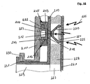
- the gap 227 is used to absorb leaking gases or liquids by a rinsing process can be removed. For this reason is in the FIG. 16 in the lower area, a connection 229 is shown, to which, for example, a pump can be connected. From this terminal 229, only the upper portion is shown graphically, with a collar-shaped transition 230 of the wall surface 211 and a collar-shaped transition 231 of the lining material 210.
- the two lining materials 210 and 221 are used here as inliner films, namely to protect the wall surface 211 , wherein through the gap 227, the possibility of premature detection of a leak can take place and beyond by flushing gases or liquids from this gap 227 are removable.
- FIG. 17 shows in a sectional side view and a plan view of a two-part embodiment of a spacer 320, as it is already known from the preceding figures.
- the spacer 320 consists of a first spacer 321, which is annularly formed with a cross-collar 322 is provided, while a second spacer 323 is annularly formed with a groove 324 in which the collar 322 of the first spacer 321 engages.
- the first spacer 321 is welded to the wall surface 326 by means of a weld 325, after which the second spacer 323 has been inserted.
- the lining material 327 is welded to the second spacer 323 with the aid of an absorbent material 328, whereby in this variant an induction welding process can likewise be used again and the absorbent material 328 is enriched either with nanoparticles or with a millbase.
Landscapes
- Engineering & Computer Science (AREA)
- General Engineering & Computer Science (AREA)
- Mechanical Engineering (AREA)
- Lining Or Joining Of Plastics Or The Like (AREA)
Claims (18)
- Dispositif de maintien pour la fixation d'un matériau de revêtement (2, 23, 48, 64, 75, 81, 91, 123, 133, 143, 154, 165, 172, 183, 200, 210, 221, 327) sur une surface de paroi (3, 24, 49, 66, 76, 82, 92, 104, 124, 134, 144, 153, 163, 173, 181, 211, 326), en particulier une paroi de contenant, d'appareil ou de dispositif, qui peut être fixé à la surface de paroi (3, 24, 49, 66, 76, 82, 92, 104, 124, 134, 144, 153, 163, 173, 181, 211, 326) au moyen d'espaceurs (1, 4, 20, 21, 22, 45, 60, 70, 80, 90, 100, 120, 130, 140, 150, 160, 171, 184, 201, 212, 220, 320),
caractérisé par le fait que
les espaceurs (1, 4, 20, 21, 22, 45, 60, 70, 80, 90, 100, 120, 130, 140, 150, 160, 171, 184, 201, 212, 220, 320) sont constitués au moins partiellement de matière plastique et peuvent être soudés par une première surface de contact (6, 14, 31, 33, 36, 40, 50, 51, 86, 88, 202, 204, 222, 224) à la surface de paroi (3, 24, 49, 66, 76, 82, 92, 104, 124, 134, 144, 153, 163, 173, 181, 211, 326) et par une seconde surface de contact (6, 14, 31, 33, 36, 40, 50, 51, 86, 88, 202, 204, 222, 224) au matériau de revêtement (2, 23, 48, 64, 75, 81, 91, 123, 133, 143, 154, 165, 172, 183, 200, 210, 221, 327). - Dispositif de maintien selon la revendication 1,
caractérisé par le fait que
la première surface de contact (6, 14, 31, 33, 36, 40, 50, 51, 86, 88, 202, 204, 222, 224) est formée sur une face frontale des espaceurs (1, 4, 20, 21, 22, 45, 60, 70, 80, 90, 100, 120, 130, 140, 150, 160, 171, 184, 201, 212, 220, 320) et/ou que la seconde surface de contact (6, 14, 31, 33, 36, 40, 50, 51, 86, 88, 202, 204, 222, 224) est formée sur une face frontale diamétralement opposée ou sur une surface y étant parallèle. - Dispositif de maintien selon la revendication 1 ou 2,
caractérisé par le fait que
les espaceurs (1, 4, 20, 21, 22, 45, 60, 70, 80, 90, 100, 120, 130, 140, 150, 160, 171, 184, 201, 212, 220, 320) sont agencés sous forme ronde, sous forme ovale ou sous forme de bande, qui sont pourvus, sur la surface de contact (6, 14, 31, 33, 36, 40, 50, 51, 86, 88, 202, 204, 222, 224) orientée vers le matériau de revêtement (2, 23, 48, 64, 75, 81, 91, 123, 133, 143, 154, 165, 172, 183, 200, 210, 221, 327), au moins par section d'un revêtement absorbant (10 ,16, 27, 28, 32, 34, 37, 41, 46, 47, 65, 87, 89, 125, 135, 145, 155, 203, 205, 218, 223, 225, 328). - Dispositif de maintien selon l'une ou plusieurs des revendications 1 à 3,
caractérisé par le fait que
la surface de contact (6, 14, 31, 33, 36, 40, 50, 51, 86, 88, 202, 204, 222, 224) orientée vers la surface de paroi (3, 24, 49, 66, 76, 82, 92, 104, 124, 134, 144, 153, 163, 173, 181, 211, 326) est pourvue au moins par section d'un revêtement absorbant (10, 16, 27, 28, 32, 34, 37, 41, 46, 47, 65, 87, 89, 125, 135, 145, 155, 203, 205, 218, 223, 225, 328) et/ou que les espaceurs (1, 4, 20, 21, 22, 45, 60, 70, 80, 90, 100, 120, 130, 140, 150, 160, 171, 184, 201, 212, 220, 320) forment en section un profilé en U, un profilé en U avec des extrémités de branches débouchantes et des surfaces de contact (6, 14, 31, 33, 36, 40, 50, 51, 86, 88, 202, 204, 222, 224) intérieures ou extérieures, un profilé en T, un profilé trapézoïdal, un profilé en V avec une large surface de base et des extrémités de branches débouchantes ou un profilé chape, ou sont constitués d'un profilé rectangulaire ou carré préférentiellement sur toute la surface. - Dispositif de maintien selon la revendication 4,
caractérisé par le fait que
les espaceurs (1, 4, 20, 21, 22, 45, 60, 70, 80, 90, 100, 120, 130, 140, 150, 160, 171, 184, 201, 212, 220, 320) sont formés de deux parties, une première partie d'espacement (61, 62, 71, 72, 73, 74, 93, 94, 101, 102, 121, 122, 131, 132, 141, 142, 151, 152, 961, 162, 213, 214, 321, 323) étant reliée à la surface de paroi (3, 24, 49, 66, 76, 82, 92, 104, 124, 134, 144, 153, 163, 173, 181, 211, 326) et une seconde partie d'espacement étant reliée au matériau de revêtement (2, 23, 48, 64, 75, 81, 91, 123, 133, 143, 154, 165, 172, 183, 200, 210, 221, 327) et les deux parties d'espacement (61, 62, 71, 72, 73, 74, 93, 94, 101, 102, 121, 122, 131, 132, 141, 142, 151, 152, 161, 162, 213, 214, 321, 323) étant reliées entre elles par une couche d'accouplement (74, 95, 128, 136, 146). - Dispositif de maintien selon la revendication 5,
caractérisé par le fait que
la couche d'accouplement (63, 74, 95, 128, 136, 146) est constituée d'une couche de colle ou d'adhésif (8, 68, 85, 106) ou de premiers et de seconds éléments d'accouplement reliés entre eux par complémentarité de forme et/ou à force ou que la couche d'accouplement (63, 74, 95, 128, 136, 146) est constituée d'une denture en queue d'aronde pouvant être comprimée, et/ou que les espaceurs (1, 4, 20, 21, 22, 45, 60, 70, 80, 90, 100, 120, 130, 140, 150, 160, 171, 184, 201, 212, 220, 320) présentent, sur une face des éléments d'accouplement, au moins un revêtement absorbant (10 ,16, 27, 28, 32, 34, 37, 41, 46, 47, 65, 87, 89, 125, 135, 145, 155, 203, 205, 218, 223, 225, 328), qui peut être soudé par un rayonnement électromagnétique. - Dispositif de maintien selon la revendication 6,
caractérisé par le fait que
les éléments d'accouplement ont une forme de T, une forme de champignon, une forme de U avec des branches débouchantes, une forme de disque, une forme ondulée avec une base intermédiaire droite, une forme de S ou une forme angulaire, des éléments d'accouplement ronds ou en forme de bande pouvant être utilisés. - Dispositif de maintien selon l'une ou plusieurs des revendications 1 à 7,
caractérisé par le fait que
les espaceurs (1, 4, 20, 21, 22, 45, 60, 70, 80, 90, 100, 120, 130, 140, 150, 160, 171, 184, 201, 212, 220, 320) peuvent être reçus dans des passages (17, 216) du matériau de revêtement (2, 23, 48, 64, 75, 81, 91, 123, 133, 143, 154, 165, 172, 183, 200, 210, 221, 327), et/ou que la surface de paroi (3, 24, 49, 66, 76, 82, 92, 104, 124, 134, 144, 153, 163, 173, 181, 211, 326) est constituée d'une matière plastique contre-collée, préférentiellement fine, qui est collée sur une paroi extérieure en métal ou en PRFV et/ou que les espaceurs (1, 4, 20, 21, 22, 45, 60, 70, 80, 90, 100, 120, 130, 140, 150, 160, 171, 184, 201, 212, 220, 320) sont reliés à une surface de paroi (3, 24, 49, 66, 76, 82, 92, 104, 124, 134, 144, 153, 163, 173, 181, 211, 326), qui est constituée d'une paroi de matière plastique ou d'une paroi métallique constituant un support stable. - Dispositif de maintien selon l'une ou plusieurs des revendications 1 à 8,
caractérisé par le fait que
un premier espaceur (1, 4, 20, 21, 22, 45, 60, 70, 80, 90, 100, 120, 130, 140, 150, 160, 171, 184, 201, 212, 220, 320) est constitué de métal en cas de réalisation des espaceurs en deux parties, avec connexion par complémentarité de forme et un second espaceur (1, 4, 20, 21, 22, 45, 60, 70, 80, 90, 100, 120, 130, 140, 150, 160, 171, 184, 201, 212, 220, 320) est constitué de matière plastique et/ou qu'un espace intermédiaire (18, 207, 227) est formé entre le matériau de revêtement (2, 23, 48, 64, 75, 81, 91, 123, 133, 143, 154, 165, 172, 183, 200, 210, 221, 327) et la surface de paroi (3, 24, 49, 66, 76, 82, 92, 104, 124, 134, 144, 153, 163, 173, 181, 211, 326). - Dispositif de maintien selon l'une ou plusieurs des revendications 1 à 9,
caractérisé par le fait
qu'un élément d'écartement, par exemple une grille en matière plastique, une gaze synthétique ou une mousse à pores ouverts est inséré dans l'espace intermédiaire (18, 207, 227). - Dispositif de maintien selon l'une ou plusieurs des revendications 1 à 10,
caractérisé par le fait que
les espaceurs (1, 4, 20, 21, 22, 45, 60, 70, 80, 90, 100, 120, 130, 140, 150, 160, 171, 184, 201, 212, 220, 320) sont constitués d'une matière plastique transparente à la lumière et/ou que les espaceurs (1, 4, 20, 21, 22, 45, 60, 70, 80, 90, 100, 120, 130, 140, 150, 160, 171, 184, 201, 212, 220, 320) sont reliés à des surfaces de paroi (3, 24, 49, 66, 76, 82, 92, 104, 124, 134, 144, 153, 163, 173, 181, 211, 326) en matière plastique absorbant la lumière et/ou que les espaceurs (1, 4, 20, 21, 22, 45, 60, 70, 80, 90, 100, 120, 130, 140, 150, 160, 171, 184, 201, 212, 220, 320) sont reliés à un matériau de revêtement (2, 23, 48, 64, 75, 81, 91, 123, 133, 143, 154, 165, 172, 183, 200, 210, 221, 327) en matière plastique transparente à la lumière. - Dispositif de maintien selon l'une ou plusieurs des revendications 1 à 11,
caractérisé par le fait que
les espaceurs (1, 4, 20, 21, 22, 45, 60, 70, 80, 90, 100, 120, 130, 140, 150, 160, 171, 184, 201, 212, 220, 320) sont reliés à une surface de paroi (3, 24, 49, 66, 76, 82, 92, 104, 124, 134, 144, 153, 163, 173, 181, 211, 326) et à un matériau de revêtement (2, 23, 48, 64, 75, 81, 91, 123, 133, 143, 154, 165, 172, 183, 200, 210, 221, 327) en matière thermoplastique standard, préférentiellement en PE, PP, PE-UHMW ou en matière thermoplastique partiellement fluorée, préférentiellement en PVDF, E-CTFE ou en matière thermoplastique à haute teneur en fluor, préférentiellement en FEP, MFA, PFA ou en PTFE modifié, et/ou que le revêtement (10 ,16, 27, 28, 32, 34, 37, 41, 46, 47, 65, 87, 89, 125, 135, 145, 155, 203, 205, 218, 223, 225, 328) est constitué de matières plastiques identiques et, pour le PE-UHMW et le PTFE, de matières plastiques similaires à celles de la surface de paroi (3, 24, 49, 66, 76, 82, 92, 104, 124, 134, 144, 153, 163, 173, 181, 211, 326) ou du matériau de revêtement (2, 23, 48, 64, 75, 81, 91, 123, 133, 143, 154, 165, 172, 183, 200,210,221,327). - Dispositif de maintien selon l'une ou plusieurs des revendications 1 à 12,
caractérisé par le fait que
les espaceurs (1, 4, 20, 21, 22, 45, 60, 70, 80, 90, 100, 120, 130, 140, 150, 160, 171, 184, 201, 212, 220, 320) peuvent être reliés à la surface de paroi (3, 24, 49, 66, 76, 82, 92, 104, 124, 134, 144, 153, 163, 173, 181, 211, 326) et/ou au matériau de revêtement (2, 23, 48, 64, 75, 81, 91, 123, 133, 143, 154, 165, 172, 183, 200, 210, 221, 327) par un revêtement absorbant un rayonnement électromagnétique (10, 16, 27, 28, 32, 34, 37, 41, 46, 47, 65, 87, 89, 125, 135, 145, 155, 203, 205, 218, 223, 225, 328) et/ou que les matières plastiques contiennent des additifs thermostables absorbant le rayonnement électromagnétique, les additifs étant constitués de particules qui sont sensibles à la lumière infrarouge ou sensibles au laser et qui sont constitués de matériaux organiques ou inorganiques à stabilité en température minimum, la température correspondant aux températures de traitement des matières plastiques utilisées et les particules étant constituées, en fonction du procédé par action thermique, par exemple d'agents colorants sous la forme de colorants ou de pigments colorés, comme de la suie ou du mica avec un revêtement étain-antimoine. - Dispositif de maintien selon l'une ou plusieurs des revendications 3 à 13,
caractérisé par le fait
que le revêtement (10, 16, 27, 28, 32, 34, 37, 41, 46, 47, 65, 87, 89, 125, 135, 145, 155, 203, 205, 218, 223, 225, 328) est constitué au moins partiellement d'additifs absorbants thermostables sous la forme de particules, les particules étant sensibles à la lumière infrarouge ou sensibles au laser et étant constituées de matériaux organiques ou inorganiques à stabilité en température minimum, qui correspondent aux températures de traitement des matières plastiques utilisées et, en fonction du procédé par action thermique, sont constituées par exemple d'agents colorants sous la forme de colorants ou de pigments colorés, comme de la suie ou du mica avec un revêtement zinc-antimoine et/ou que les matières plastiques et les revêtements (10 , 16, 27, 28, 32, 34, 37, 41, 46, 47, 65, 87, 89, 125, 135, 145, 155, 243, 205, 218, 223, 225, 328) absorbent le rayonnement électromagnétique dans la plage de longueur d'onde de 150 à 2.500 nanomètres, préférentiellement de 500 à 1.500 nanomètres, particulièrement préférentiellement de 800 à 1.000 nanomètres. - Dispositif de maintien selon l'une ou plusieurs des revendications 3 à 14,
caractérisé par le fait
qu'un laser à solide, un laser à verre, un laser semiconducteur ou une source de lumière infrarouge, par exemple une lampe à arc court au xénon, sont utilisés comme source de rayonnement électromagnétique ou un laser CO2 peut être utilisé pour la plastification de la matière plastique et le revêtement (10, 16, 27, 28, 32, 34, 37, 41, 46, 47, 65, 87, 89, 125, 135, 145, 155, 203, 205, 218, 223, 225, 328). - Dispositif de maintien selon l'une ou plusieurs des revendications 3 à 15,
caractérisé par le fait que
un dispositif de soudage par induction peut être utilisé pour la plastification du revêtement absorbant (10 , 16, 27, 28, 32, 34, 37, 41, 46, 47, 65, 87, 89, 125, 135, 145, 155, 203, 205, 218, 223, 225, 328), le revêtement absorbant (10, 16, 27, 28, 32, 34, 37, 41, 46, 47, 65, 87, 89, 125, 135, 145, 155, 203, 205, 218, 223, 225, 328), le matériau de revêtement (2, 23, 48, 64, 75, 81, 91, 123, 133, 143, 154, 165, 172, 183, 200, 210, 221, 327), les éléments d'accouplement et/ou les espaceurs (1, 4, 20, 21, 22, 45, 60, 70, 80, 90, 100, 120, 130, 140, 150, 160, 171, 184, 201, 212, 220, 320) étant au moins partiellement enrichis en matière de charge, par exemple en nanoparticules ou en matière moulue. - Dispositif de maintien selon la revendication 16,
caractérisé par le fait que
la matière de charge présente des propriétés magnétiques, ferrimagnétiques, ferromagnétiques, antiferromagnétiques ou supraparamagnétiques, la matière de charge présentant une taille de particule moyenne située entre 1 et 500 nm, préférentiellement entre 2 et 100 nm, et/ou que la matière de charge contenant des particules oxydées magnétiques nanométriques constituées de particules primaires agrégées ou que la matière de charge est constituée de ferrites, d'oxydes ou d'oxydes métalliques mixtes et/ou que la matière de charge, par exemple les nanoparticules ou la matière moulue, est constituée préférentiellement de métal, par exemple de nickel, d'argent, d'or, de cobalt, de fer, d'aluminium, d'étain, de zinc, ou de matériau spécial, par exemple de zirconium, de palladium, d'indium, de molybdène, de tantale, de rhénium, de titane et/ou d'un mélange ou d'un alliage des métaux ou des matières spéciales mentionnés. - Dispositif de maintien selon la revendication 16,
caractérisé par le fait que
les matières de charge sont inertes et/ou que les nanoparticules ou la matière moulue sont recouvertes de céramique et/ou qu'un rayonnement micro-ondes ayant une fréquence située dans la plage de 1,5 à 10 GHz, préférentiellement dans la plage de 2 à 3 GHz est prévu pour la plastification du revêtement absorbant (10, 16, 27, 28, 32, 34, 37, 41, 46, 47, 65, 87, 89, 125, 135, 145, 155, 203, 205, 218, 223, 225, 328).
Applications Claiming Priority (3)
| Application Number | Priority Date | Filing Date | Title |
|---|---|---|---|
| DE102008017516 | 2008-04-04 | ||
| DE102008028815A DE102008028815A1 (de) | 2008-04-04 | 2008-06-19 | Haltevorrichtung für Auskleidungsmaterialien |
| PCT/DE2009/000434 WO2009121345A1 (fr) | 2008-04-04 | 2009-04-03 | Dispositif de fixation de matériaux de garniture |
Publications (2)
| Publication Number | Publication Date |
|---|---|
| EP2268929A1 EP2268929A1 (fr) | 2011-01-05 |
| EP2268929B1 true EP2268929B1 (fr) | 2013-05-15 |
Family
ID=41051570
Family Applications (1)
| Application Number | Title | Priority Date | Filing Date |
|---|---|---|---|
| EP09727988.9A Active EP2268929B1 (fr) | 2008-04-04 | 2009-04-03 | Dispositif de fixation de matériaux de garniture |
Country Status (3)
| Country | Link |
|---|---|
| EP (1) | EP2268929B1 (fr) |
| DE (1) | DE102008028815A1 (fr) |
| WO (1) | WO2009121345A1 (fr) |
Cited By (1)
| Publication number | Priority date | Publication date | Assignee | Title |
|---|---|---|---|---|
| DE102016005903A1 (de) * | 2016-05-13 | 2017-11-16 | Audi Ag | Verfahren zum Verbinden von Bauteilen |
Family Cites Families (3)
| Publication number | Priority date | Publication date | Assignee | Title |
|---|---|---|---|---|
| GB1222829A (en) | 1967-12-01 | 1971-02-17 | Rose Downs & Thompson Ltd | Improvements in or relating to welding a stay to spaced parts |
| US5298098A (en) | 1991-03-22 | 1994-03-29 | Hoedl Herbert K | Industrial pallets and methods of manufacture of panel structures |
| DE10131510A1 (de) | 2001-07-02 | 2003-04-03 | Newfrey Llc | Befestigungselement und Verfahren zu seiner Herstellung sowie Verwendung |
-
2008
- 2008-06-19 DE DE102008028815A patent/DE102008028815A1/de not_active Withdrawn
-
2009
- 2009-04-03 WO PCT/DE2009/000434 patent/WO2009121345A1/fr not_active Ceased
- 2009-04-03 EP EP09727988.9A patent/EP2268929B1/fr active Active
Cited By (1)
| Publication number | Priority date | Publication date | Assignee | Title |
|---|---|---|---|---|
| DE102016005903A1 (de) * | 2016-05-13 | 2017-11-16 | Audi Ag | Verfahren zum Verbinden von Bauteilen |
Also Published As
| Publication number | Publication date |
|---|---|
| EP2268929A1 (fr) | 2011-01-05 |
| DE102008028815A1 (de) | 2009-10-08 |
| WO2009121345A1 (fr) | 2009-10-08 |
Similar Documents
| Publication | Publication Date | Title |
|---|---|---|
| DE2845602C2 (fr) | ||
| DE2925538C2 (de) | Schichtstoffmaterial | |
| DE60122188T2 (de) | Temperaturkontrollierte induktionserwärmung polymerer materialien | |
| DE69031363T2 (de) | Verfahren zum Verbinden von Kunststoffen und Heizvorrichtung zum Verbinden von Kunststoffen | |
| EP2435236B1 (fr) | Dispositif de positionnement pour un appareil de soudage manuel | |
| DE69225480T2 (de) | Verfahren zum induktionsheizen von verbundwerkstoffen | |
| DE102017109362A1 (de) | Kosmetische Reparatur eines thermoplastischen Kohlenstofffaserkomposits | |
| DE102013105075B4 (de) | Harzformkörper und Verfahren zu seiner Herstellung | |
| DE102015112874A1 (de) | Mechanische Verriegelung, die durch Induktionserwärmen zur Polymerkompositreparatur bewirkt wird | |
| DE102009026216A1 (de) | Flexibles Flächengebilde | |
| EP2014734A1 (fr) | Bande collante | |
| EP1943084B1 (fr) | Corps moules composites plastiques obtenus par soudage dans un champ electromagnetique alternatif | |
| DE102017119491A1 (de) | Verfahren und Vorrichtung zum Verschweißen von einem Duromer-Objekt mit einem weiteren Objekt über thermoplastische äußere Schichten | |
| DE102019106446A1 (de) | Verfahren zur Herstellung einer thermoplastischen Fügeverbindung, Verfahren zur Reparatur eines ersten Bauteils und Fügeverbindung | |
| EP2268929B1 (fr) | Dispositif de fixation de matériaux de garniture | |
| DE102006040049A1 (de) | Verfahren und Vorrichtung zum Vorformen von Kohlenstofffaser-Halbzeugen für die Herstellung von Faserverbundbauteilen | |
| WO2009121346A2 (fr) | Dispositif de fixation de matériaux de garniture | |
| EP3071872A1 (fr) | Flexible de doublage pour la rénovation de systèmes de conduites guidant des fluides | |
| DE102007042807A1 (de) | Heizwendelmuffe | |
| DE102019008289A1 (de) | Effektpigment, Herstellungsverfahren, Wertdokument und Druckfarbe | |
| DE102015222543A1 (de) | Intelligentes Fenster unter Verwendung von Glasperlen und Flüssigkristall, und Herstellungsverfahren hierfür | |
| DE102007042806A1 (de) | Verfahren zum Verschweißen von Kunststoffrohren | |
| WO2002084680A1 (fr) | Procede pour definir des magnetisations de reference dans des systemes de couches | |
| EP2293922A2 (fr) | Appareil de soudage à main | |
| DE102021005029B4 (de) | Druckrohrmuffenverbindung |
Legal Events
| Date | Code | Title | Description |
|---|---|---|---|
| PUAI | Public reference made under article 153(3) epc to a published international application that has entered the european phase |
Free format text: ORIGINAL CODE: 0009012 |
|
| 17P | Request for examination filed |
Effective date: 20101104 |
|
| AK | Designated contracting states |
Kind code of ref document: A1 Designated state(s): AT BE BG CH CY CZ DE DK EE ES FI FR GB GR HR HU IE IS IT LI LT LU LV MC MK MT NL NO PL PT RO SE SI SK TR |
|
| AX | Request for extension of the european patent |
Extension state: AL BA RS |
|
| DAX | Request for extension of the european patent (deleted) | ||
| 17Q | First examination report despatched |
Effective date: 20110905 |
|
| GRAP | Despatch of communication of intention to grant a patent |
Free format text: ORIGINAL CODE: EPIDOSNIGR1 |
|
| GRAS | Grant fee paid |
Free format text: ORIGINAL CODE: EPIDOSNIGR3 |
|
| GRAA | (expected) grant |
Free format text: ORIGINAL CODE: 0009210 |
|
| AK | Designated contracting states |
Kind code of ref document: B1 Designated state(s): AT BE BG CH CY CZ DE DK EE ES FI FR GB GR HR HU IE IS IT LI LT LU LV MC MK MT NL NO PL PT RO SE SI SK TR |
|
| REG | Reference to a national code |
Ref country code: GB Ref legal event code: FG4D Free format text: NOT ENGLISH Ref country code: CH Ref legal event code: EP |
|
| REG | Reference to a national code |
Ref country code: AT Ref legal event code: REF Ref document number: 612307 Country of ref document: AT Kind code of ref document: T Effective date: 20130615 |
|
| REG | Reference to a national code |
Ref country code: IE Ref legal event code: FG4D Free format text: LANGUAGE OF EP DOCUMENT: GERMAN |
|
| REG | Reference to a national code |
Ref country code: DE Ref legal event code: R096 Ref document number: 502009007105 Country of ref document: DE Effective date: 20130711 |
|
| REG | Reference to a national code |
Ref country code: LT Ref legal event code: MG4D |
|
| REG | Reference to a national code |
Ref country code: NL Ref legal event code: VDEP Effective date: 20130515 |
|
| PG25 | Lapsed in a contracting state [announced via postgrant information from national office to epo] |
Ref country code: NO Free format text: LAPSE BECAUSE OF FAILURE TO SUBMIT A TRANSLATION OF THE DESCRIPTION OR TO PAY THE FEE WITHIN THE PRESCRIBED TIME-LIMIT Effective date: 20130815 Ref country code: PT Free format text: LAPSE BECAUSE OF FAILURE TO SUBMIT A TRANSLATION OF THE DESCRIPTION OR TO PAY THE FEE WITHIN THE PRESCRIBED TIME-LIMIT Effective date: 20130916 Ref country code: SE Free format text: LAPSE BECAUSE OF FAILURE TO SUBMIT A TRANSLATION OF THE DESCRIPTION OR TO PAY THE FEE WITHIN THE PRESCRIBED TIME-LIMIT Effective date: 20130515 Ref country code: SI Free format text: LAPSE BECAUSE OF FAILURE TO SUBMIT A TRANSLATION OF THE DESCRIPTION OR TO PAY THE FEE WITHIN THE PRESCRIBED TIME-LIMIT Effective date: 20130515 Ref country code: ES Free format text: LAPSE BECAUSE OF FAILURE TO SUBMIT A TRANSLATION OF THE DESCRIPTION OR TO PAY THE FEE WITHIN THE PRESCRIBED TIME-LIMIT Effective date: 20130826 Ref country code: GR Free format text: LAPSE BECAUSE OF FAILURE TO SUBMIT A TRANSLATION OF THE DESCRIPTION OR TO PAY THE FEE WITHIN THE PRESCRIBED TIME-LIMIT Effective date: 20130816 Ref country code: FI Free format text: LAPSE BECAUSE OF FAILURE TO SUBMIT A TRANSLATION OF THE DESCRIPTION OR TO PAY THE FEE WITHIN THE PRESCRIBED TIME-LIMIT Effective date: 20130515 Ref country code: IS Free format text: LAPSE BECAUSE OF FAILURE TO SUBMIT A TRANSLATION OF THE DESCRIPTION OR TO PAY THE FEE WITHIN THE PRESCRIBED TIME-LIMIT Effective date: 20130915 Ref country code: LT Free format text: LAPSE BECAUSE OF FAILURE TO SUBMIT A TRANSLATION OF THE DESCRIPTION OR TO PAY THE FEE WITHIN THE PRESCRIBED TIME-LIMIT Effective date: 20130515 |
|
| PG25 | Lapsed in a contracting state [announced via postgrant information from national office to epo] |
Ref country code: PL Free format text: LAPSE BECAUSE OF FAILURE TO SUBMIT A TRANSLATION OF THE DESCRIPTION OR TO PAY THE FEE WITHIN THE PRESCRIBED TIME-LIMIT Effective date: 20130515 Ref country code: HR Free format text: LAPSE BECAUSE OF FAILURE TO SUBMIT A TRANSLATION OF THE DESCRIPTION OR TO PAY THE FEE WITHIN THE PRESCRIBED TIME-LIMIT Effective date: 20130515 Ref country code: BG Free format text: LAPSE BECAUSE OF FAILURE TO SUBMIT A TRANSLATION OF THE DESCRIPTION OR TO PAY THE FEE WITHIN THE PRESCRIBED TIME-LIMIT Effective date: 20130815 |
|
| PG25 | Lapsed in a contracting state [announced via postgrant information from national office to epo] |
Ref country code: LV Free format text: LAPSE BECAUSE OF FAILURE TO SUBMIT A TRANSLATION OF THE DESCRIPTION OR TO PAY THE FEE WITHIN THE PRESCRIBED TIME-LIMIT Effective date: 20130515 |
|
| PG25 | Lapsed in a contracting state [announced via postgrant information from national office to epo] |
Ref country code: EE Free format text: LAPSE BECAUSE OF FAILURE TO SUBMIT A TRANSLATION OF THE DESCRIPTION OR TO PAY THE FEE WITHIN THE PRESCRIBED TIME-LIMIT Effective date: 20130515 Ref country code: SK Free format text: LAPSE BECAUSE OF FAILURE TO SUBMIT A TRANSLATION OF THE DESCRIPTION OR TO PAY THE FEE WITHIN THE PRESCRIBED TIME-LIMIT Effective date: 20130515 Ref country code: DK Free format text: LAPSE BECAUSE OF FAILURE TO SUBMIT A TRANSLATION OF THE DESCRIPTION OR TO PAY THE FEE WITHIN THE PRESCRIBED TIME-LIMIT Effective date: 20130515 Ref country code: CZ Free format text: LAPSE BECAUSE OF FAILURE TO SUBMIT A TRANSLATION OF THE DESCRIPTION OR TO PAY THE FEE WITHIN THE PRESCRIBED TIME-LIMIT Effective date: 20130515 |
|
| PG25 | Lapsed in a contracting state [announced via postgrant information from national office to epo] |
Ref country code: RO Free format text: LAPSE BECAUSE OF FAILURE TO SUBMIT A TRANSLATION OF THE DESCRIPTION OR TO PAY THE FEE WITHIN THE PRESCRIBED TIME-LIMIT Effective date: 20130515 Ref country code: NL Free format text: LAPSE BECAUSE OF FAILURE TO SUBMIT A TRANSLATION OF THE DESCRIPTION OR TO PAY THE FEE WITHIN THE PRESCRIBED TIME-LIMIT Effective date: 20130515 Ref country code: IT Free format text: LAPSE BECAUSE OF FAILURE TO SUBMIT A TRANSLATION OF THE DESCRIPTION OR TO PAY THE FEE WITHIN THE PRESCRIBED TIME-LIMIT Effective date: 20130515 |
|
| PLBE | No opposition filed within time limit |
Free format text: ORIGINAL CODE: 0009261 |
|
| STAA | Information on the status of an ep patent application or granted ep patent |
Free format text: STATUS: NO OPPOSITION FILED WITHIN TIME LIMIT |
|
| 26N | No opposition filed |
Effective date: 20140218 |
|
| REG | Reference to a national code |
Ref country code: DE Ref legal event code: R097 Ref document number: 502009007105 Country of ref document: DE Effective date: 20140218 |
|
| REG | Reference to a national code |
Ref country code: IE Ref legal event code: MM4A |
|
| PG25 | Lapsed in a contracting state [announced via postgrant information from national office to epo] |
Ref country code: IE Free format text: LAPSE BECAUSE OF NON-PAYMENT OF DUE FEES Effective date: 20140403 |
|
| REG | Reference to a national code |
Ref country code: AT Ref legal event code: MM01 Ref document number: 612307 Country of ref document: AT Kind code of ref document: T Effective date: 20140403 |
|
| PG25 | Lapsed in a contracting state [announced via postgrant information from national office to epo] |
Ref country code: AT Free format text: LAPSE BECAUSE OF NON-PAYMENT OF DUE FEES Effective date: 20140403 |
|
| PG25 | Lapsed in a contracting state [announced via postgrant information from national office to epo] |
Ref country code: MT Free format text: LAPSE BECAUSE OF FAILURE TO SUBMIT A TRANSLATION OF THE DESCRIPTION OR TO PAY THE FEE WITHIN THE PRESCRIBED TIME-LIMIT Effective date: 20130515 |
|
| REG | Reference to a national code |
Ref country code: FR Ref legal event code: PLFP Year of fee payment: 8 |
|
| PG25 | Lapsed in a contracting state [announced via postgrant information from national office to epo] |
Ref country code: CY Free format text: LAPSE BECAUSE OF FAILURE TO SUBMIT A TRANSLATION OF THE DESCRIPTION OR TO PAY THE FEE WITHIN THE PRESCRIBED TIME-LIMIT Effective date: 20130515 |
|
| PG25 | Lapsed in a contracting state [announced via postgrant information from national office to epo] |
Ref country code: HU Free format text: LAPSE BECAUSE OF FAILURE TO SUBMIT A TRANSLATION OF THE DESCRIPTION OR TO PAY THE FEE WITHIN THE PRESCRIBED TIME-LIMIT; INVALID AB INITIO Effective date: 20090403 Ref country code: TR Free format text: LAPSE BECAUSE OF FAILURE TO SUBMIT A TRANSLATION OF THE DESCRIPTION OR TO PAY THE FEE WITHIN THE PRESCRIBED TIME-LIMIT Effective date: 20130515 |
|
| REG | Reference to a national code |
Ref country code: FR Ref legal event code: PLFP Year of fee payment: 9 |
|
| REG | Reference to a national code |
Ref country code: FR Ref legal event code: PLFP Year of fee payment: 10 |
|
| PG25 | Lapsed in a contracting state [announced via postgrant information from national office to epo] |
Ref country code: MK Free format text: LAPSE BECAUSE OF FAILURE TO SUBMIT A TRANSLATION OF THE DESCRIPTION OR TO PAY THE FEE WITHIN THE PRESCRIBED TIME-LIMIT Effective date: 20130515 |
|
| PGFP | Annual fee paid to national office [announced via postgrant information from national office to epo] |
Ref country code: MC Payment date: 20180419 Year of fee payment: 10 |
|
| PGFP | Annual fee paid to national office [announced via postgrant information from national office to epo] |
Ref country code: NL Payment date: 20180712 Year of fee payment: 10 |
|
| GBPC | Gb: european patent ceased through non-payment of renewal fee |
Effective date: 20190403 |
|
| PG25 | Lapsed in a contracting state [announced via postgrant information from national office to epo] |
Ref country code: MC Free format text: LAPSE BECAUSE OF NON-PAYMENT OF DUE FEES Effective date: 20190430 |
|
| PG25 | Lapsed in a contracting state [announced via postgrant information from national office to epo] |
Ref country code: GB Free format text: LAPSE BECAUSE OF NON-PAYMENT OF DUE FEES Effective date: 20190403 |
|
| P01 | Opt-out of the competence of the unified patent court (upc) registered |
Effective date: 20230601 |
|
| REG | Reference to a national code |
Ref country code: DE Ref legal event code: R082 Ref document number: 502009007105 Country of ref document: DE Representative=s name: SEYER & NOBBE PATENTANWAELTE PARTNERSCHAFTSGES, DE |
|
| PGFP | Annual fee paid to national office [announced via postgrant information from national office to epo] |
Ref country code: LU Payment date: 20250417 Year of fee payment: 17 |
|
| PGFP | Annual fee paid to national office [announced via postgrant information from national office to epo] |
Ref country code: DE Payment date: 20250227 Year of fee payment: 17 |
|
| PGFP | Annual fee paid to national office [announced via postgrant information from national office to epo] |
Ref country code: BE Payment date: 20250422 Year of fee payment: 17 |
|
| PGFP | Annual fee paid to national office [announced via postgrant information from national office to epo] |
Ref country code: FR Payment date: 20250422 Year of fee payment: 17 |
|
| PGFP | Annual fee paid to national office [announced via postgrant information from national office to epo] |
Ref country code: CH Payment date: 20250501 Year of fee payment: 17 |