EP2270320A2 - Supports de sondes et leur procédé de fabrication - Google Patents
Supports de sondes et leur procédé de fabrication Download PDFInfo
- Publication number
- EP2270320A2 EP2270320A2 EP10003970A EP10003970A EP2270320A2 EP 2270320 A2 EP2270320 A2 EP 2270320A2 EP 10003970 A EP10003970 A EP 10003970A EP 10003970 A EP10003970 A EP 10003970A EP 2270320 A2 EP2270320 A2 EP 2270320A2
- Authority
- EP
- European Patent Office
- Prior art keywords
- probe
- inner sleeve
- outer sleeve
- neck
- sleeve
- Prior art date
- Legal status (The legal status is an assumption and is not a legal conclusion. Google has not performed a legal analysis and makes no representation as to the accuracy of the status listed.)
- Granted
Links
Images

Classifications
-
- F—MECHANICAL ENGINEERING; LIGHTING; HEATING; WEAPONS; BLASTING
- F16—ENGINEERING ELEMENTS AND UNITS; GENERAL MEASURES FOR PRODUCING AND MAINTAINING EFFECTIVE FUNCTIONING OF MACHINES OR INSTALLATIONS; THERMAL INSULATION IN GENERAL
- F16L—PIPES; JOINTS OR FITTINGS FOR PIPES; SUPPORTS FOR PIPES, CABLES OR PROTECTIVE TUBING; MEANS FOR THERMAL INSULATION IN GENERAL
- F16L41/00—Branching pipes; Joining pipes to walls
- F16L41/08—Joining pipes to walls or pipes, the joined pipe axis being perpendicular to the plane of a wall or to the axis of another pipe
- F16L41/10—Joining pipes to walls or pipes, the joined pipe axis being perpendicular to the plane of a wall or to the axis of another pipe the extremity of the pipe being screwed into the wall
-
- F—MECHANICAL ENGINEERING; LIGHTING; HEATING; WEAPONS; BLASTING
- F01—MACHINES OR ENGINES IN GENERAL; ENGINE PLANTS IN GENERAL; STEAM ENGINES
- F01N—GAS-FLOW SILENCERS OR EXHAUST APPARATUS FOR MACHINES OR ENGINES IN GENERAL; GAS-FLOW SILENCERS OR EXHAUST APPARATUS FOR INTERNAL-COMBUSTION ENGINES
- F01N13/00—Exhaust or silencing apparatus characterised by constructional features
- F01N13/008—Mounting or arrangement of exhaust sensors in or on exhaust apparatus
-
- F—MECHANICAL ENGINEERING; LIGHTING; HEATING; WEAPONS; BLASTING
- F01—MACHINES OR ENGINES IN GENERAL; ENGINE PLANTS IN GENERAL; STEAM ENGINES
- F01N—GAS-FLOW SILENCERS OR EXHAUST APPARATUS FOR MACHINES OR ENGINES IN GENERAL; GAS-FLOW SILENCERS OR EXHAUST APPARATUS FOR INTERNAL-COMBUSTION ENGINES
- F01N13/00—Exhaust or silencing apparatus characterised by constructional features
- F01N13/08—Other arrangements or adaptations of exhaust conduits
-
- F—MECHANICAL ENGINEERING; LIGHTING; HEATING; WEAPONS; BLASTING
- F16—ENGINEERING ELEMENTS AND UNITS; GENERAL MEASURES FOR PRODUCING AND MAINTAINING EFFECTIVE FUNCTIONING OF MACHINES OR INSTALLATIONS; THERMAL INSULATION IN GENERAL
- F16L—PIPES; JOINTS OR FITTINGS FOR PIPES; SUPPORTS FOR PIPES, CABLES OR PROTECTIVE TUBING; MEANS FOR THERMAL INSULATION IN GENERAL
- F16L41/00—Branching pipes; Joining pipes to walls
- F16L41/008—Branching pipes; Joining pipes to walls for connecting a measuring instrument
Definitions
- the invention relates to a probe neck for a probe having a receiving area for receiving the probe and a mounting area for attaching the probe neck to a base body and a method for its preparation.
- Generic probe neck are for example from the DE 42 24 251 C1 , of the DE 10 2005 018 881 A1 or the DE 10 2006 024 944 A1 known.
- These known probe neck are designed as a solid annular body, the outside of which is designed dome-shaped or spherical cap. This allows the arrangement of the probe nozzle in different angular positions on tubular exhaust pipes to accommodate a probe for measuring exhaust gas.
- These solid annular probe stubs are placed in a corresponding opening in the tubular exhaust pipe and connected thereto by welding. The measuring probe can then be screwed into an inside receiving area of the probe neck, so that the probe protrudes into the exhaust pipe.
- the connecting joint between the exhaust pipe and the outside of the probe neck is partially hidden in these known probe neck and not or only partially accessible for normal welding equipment.
- a closed weld is of great importance for the tightness of the exhaust pipe.
- a heat distortion also occur on the inside of the annular probe neck. As a result, screwing the sensitive probe can be impaired or even impossible.
- the invention has for its object to provide a probe neck and a method which allow a reliable attachment or which a simple and inexpensive production of a probe neck.
- the probe neck according to the invention is characterized in that the probe neck is made in one piece from a metal sheet, that for forming the receiving area an inner sleeve and for forming the fastening area an outer sleeve are formed, which is radially spaced from the inner sleeve, and that the inner sleeve and the outer sleeve over a Connecting web are connected together.
- a basic idea of the invention can be seen in spatially separating the receiving area for the measuring probe from the mounting area.
- the receiving region is formed by an inner sleeve, while the attachment region comprises an outer sleeve.
- Inner sleeve and outer sleeve are exclusively via an annular connecting web with each other.
- the receiving area for the measuring probe and the fixing area can be formed independently of one another, according to the respective requirements.
- the probe neck is formed in an economical manner by sheet metal forming.
- the manufacturing process of sheet metal forming is material and energy saving.
- a high component strength is achieved with a low material usage.
- the resulting low component weight is particularly advantageous for the use of the probe nozzle to tubular exhaust pipes of motor vehicles.
- the inner sleeve can be provided with any fastening devices for holding the measuring probe. According to the invention, however, it is particularly preferred that the inner sleeve for receiving the measuring probe is provided with an internal thread.
- the measuring probe which is preferably a so-called lambda probe for use in controlled catalysts, has a corresponding external thread. It is an advantage of the invention that the inner sleeve with respect to diameter and length can be designed independently of the shape of the outer sleeve and adapted to the dimensions of the probe. Measuring probes are also to be understood as meaning other sensors and measuring devices which can be used, for example, for measuring the temperature, humidity or other values required for engine control.
- the further preferred embodiment of the invention is that the outer sleeve has a radially outwardly projecting edge.
- a contact area with the base body to be connected which is usually a tubular exhaust pipe, can be increased.
- the thus radially outwardly projecting edge flange increases the contact area with the body, increases the contact gap and extends the circumferential line.
- the peripheral line can be formed with an arbitrary contour, so that the edge can have a different width along the circumference. This facilitates the welding of the probe neck to the body and is conducive to a reliable tightness of the connection.
- a particularly stable formation of the probe neck is achieved in that the outer sleeve is arranged coaxially to the inner sleeve.
- An alternative embodiment of the invention is that a center axis of the inner sleeve offset and / or angled to a center axis of the outer sleeve is arranged.
- the wall thicknesses of the inner sleeve, the outer sleeve and the connecting web are the same. As a result, a similar thermal and vibration behavior is achieved in the individual parts. This protects the probe and increases its service life.
- the outer sleeve can be attached to the outside of the tubular base body and the inner sleeve does not necessarily have to protrude into the interior of the tubular exhaust pipe.
- the inner sleeve does not protrude beyond the edge flange of the outer sleeve. An unnecessary impairment of the flow within the exhaust pipe or another flow line through the probe neck can be avoided.
- the opening in the body or the exhaust pipe must not be exactly adapted to the contour of the probe neck. This also simplifies the production of the body or the exhaust pipe considerably.
- the probe neck is fixed to an opening in an exhaust pipe as a base body, wherein a diameter of the opening is larger than a diameter of the inner sleeve and smaller than a diameter of the outer sleeve or the edge of the outer sleeve.
- the diameters basically refer to the respective outer diameters and are not limited to purely circular openings or sleeve contours.
- the openings and contours may be oval, angular or deviating designed.
- the probe neck according to the invention can be produced by any manufacturing process, in particular various forming processes. According to the invention, it is particularly preferred that the probe neck is formed by deep drawing and everting a sheet metal blank. Blechronde is to be understood as a substantially circular disk-shaped sheet metal part.
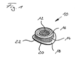
- An inventive probe neck 10 has an inner sleeve 12 and a coaxially arranged outer sleeve 14, which are connected to each other in the upper region by an annular cross-sectionally curved connecting web 16.
- At the lower portion of the outer sleeve 14 extends a radially protruding brim-like edge 18, the underside of which is designed as a contact region 20 for a cylindrical pipe-shaped exhaust pipe.
- the probe protection 10 can be welded to an exhaust gas line.
- other types of connections in particular adhesive joints, are conceivable.
- the edge 18 of the outer sleeve 14 is used for attachment to an exhaust pipe
- the inside of the inner sleeve 12 is formed for receiving and for holding a measuring probe, not shown.
- a measuring probe not shown.
- an internal thread is formed, which in Fig. 1 but not shown.
- the axially projecting inner sleeve 12 is first formed by a deep-drawing step from the flat sheet metal blank, wherein the center opening is punched out.
- the outer bladder region 2 is then formed in several deep-drawing or Stülp suitsen in the axial direction approximately coaxially with the inner sleeve 12.
- the outer sleeve 14 is formed coaxially with a central axis 24 of the inner sleeve.
- a remaining planar intermediate portion which merges with suitable radii in the inner sleeve 12 and the outer sleeve 14, forms the connecting web 16 between the inner sleeve 12 and the outer sleeve 14th
- the inner sleeve 12 and the outer sleeve 14 are radially spaced from each other so that between the outer side of the inner sleeve 12 and the inner side of the outer sleeve 14, an annular space 26 is formed.
- the outer sleeve 14 has from the inner sleeve 12 at a distance which is a multiple of the wall thickness of the sheet.
- a radially projecting edge 18 is formed, which serves as a mounting flange.
- the underside of the edge 18 can be formed in any way as a free-form surface, so that a large contact area 20 for connection to the curved outside of a tubular exhaust pipe or a differently shaped body is possible.
- the fastening of the probe neck 10 is then preferably carried out by welding by means of a closed weld along a circumferential line 22 on the outside of the rim 18.
- the invention comprises not only the described probe nozzle 10 but also the corresponding exhaust pipe element which is connected to the probe nozzle according to the invention, and a manufacturing method for producing the probe nozzle from a piece of sheet metal.
Landscapes
- Engineering & Computer Science (AREA)
- General Engineering & Computer Science (AREA)
- Mechanical Engineering (AREA)
- Chemical & Material Sciences (AREA)
- Combustion & Propulsion (AREA)
- Analytical Chemistry (AREA)
- Exhaust Silencers (AREA)
- Golf Clubs (AREA)
- Sampling And Sample Adjustment (AREA)
Applications Claiming Priority (1)
| Application Number | Priority Date | Filing Date | Title |
|---|---|---|---|
| DE200920008997 DE202009008997U1 (de) | 2009-06-30 | 2009-06-30 | Sondenstutzen |
Publications (3)
| Publication Number | Publication Date |
|---|---|
| EP2270320A2 true EP2270320A2 (fr) | 2011-01-05 |
| EP2270320A3 EP2270320A3 (fr) | 2013-04-10 |
| EP2270320B1 EP2270320B1 (fr) | 2018-12-19 |
Family
ID=41051958
Family Applications (1)
| Application Number | Title | Priority Date | Filing Date |
|---|---|---|---|
| EP10003970.0A Active EP2270320B1 (fr) | 2009-06-30 | 2010-04-14 | Supports de sondes et leur procédé de fabrication |
Country Status (2)
| Country | Link |
|---|---|
| EP (1) | EP2270320B1 (fr) |
| DE (1) | DE202009008997U1 (fr) |
Cited By (5)
| Publication number | Priority date | Publication date | Assignee | Title |
|---|---|---|---|---|
| DE102013207406A1 (de) | 2013-01-04 | 2014-07-10 | Eberspächer Exhaust Technology GmbH & Co. KG | Verfahren zum Herstellen einer Messsonden-Buchse zum Aufnehmen einer Messsonde |
| CN107514418A (zh) * | 2016-06-17 | 2017-12-26 | 超捷紧固系统(上海)股份有限公司 | 冷镦成型的排气管用传感器焊接螺套及其制造方法 |
| EP3699409A1 (fr) | 2019-02-20 | 2020-08-26 | Eberspächer Exhaust Technology GmbH | Manchon de sonde pour une installation de gaz d'échappement |
| WO2021223859A1 (fr) * | 2020-05-05 | 2021-11-11 | Vega Grieshaber Kg | Unité de montage de capteur universelle |
| WO2023232457A1 (fr) * | 2022-06-02 | 2023-12-07 | Ifm Electronic Gmbh | Adaptateur à soudure pour relier un capteur ou un actionneur à un contenant, et ensemble comprenant un adaptateur à soudure de ce type |
Citations (5)
| Publication number | Priority date | Publication date | Assignee | Title |
|---|---|---|---|---|
| DE4022303A1 (de) | 1990-07-13 | 1992-01-16 | Knorr Bremse Ag | Betaetigungszylinder mit stutzen |
| DE4224251C1 (de) | 1992-07-22 | 1993-12-02 | Zeuna Staerker Kg | Rohr- oder Schalenelement einer Abgasleitung mit einem Sondenstutzen |
| DE20120895U1 (de) | 2001-12-28 | 2002-05-23 | J. Eberspächer GmbH & Co. KG, 73730 Esslingen | Anschlußelement |
| DE102005018881A1 (de) | 2005-04-22 | 2006-10-26 | Arvinmeritor Emissions Technologies Gmbh | Abgasleitungsabschnitt |
| DE102006024944A1 (de) | 2006-05-29 | 2007-12-06 | Arvinmeritor Emissions Technologies Gmbh | Abgasleitungsabschnitt sowie Verfahren zu Befestigung eines Stutzens an einer Abgasleitung |
Family Cites Families (3)
| Publication number | Priority date | Publication date | Assignee | Title |
|---|---|---|---|---|
| JPH1026037A (ja) * | 1996-07-09 | 1998-01-27 | Yutaka Giken Co Ltd | センサ取付ボス |
| JP4604267B2 (ja) * | 2001-03-23 | 2011-01-05 | 株式会社三五 | 排気管 |
| FR2851486A1 (fr) * | 2003-02-24 | 2004-08-27 | Faurecia Sys Echappement | Procede pour la mise en place d'un piquage taraude sur un tube paroi mince |
-
2009
- 2009-06-30 DE DE200920008997 patent/DE202009008997U1/de not_active Expired - Lifetime
-
2010
- 2010-04-14 EP EP10003970.0A patent/EP2270320B1/fr active Active
Patent Citations (5)
| Publication number | Priority date | Publication date | Assignee | Title |
|---|---|---|---|---|
| DE4022303A1 (de) | 1990-07-13 | 1992-01-16 | Knorr Bremse Ag | Betaetigungszylinder mit stutzen |
| DE4224251C1 (de) | 1992-07-22 | 1993-12-02 | Zeuna Staerker Kg | Rohr- oder Schalenelement einer Abgasleitung mit einem Sondenstutzen |
| DE20120895U1 (de) | 2001-12-28 | 2002-05-23 | J. Eberspächer GmbH & Co. KG, 73730 Esslingen | Anschlußelement |
| DE102005018881A1 (de) | 2005-04-22 | 2006-10-26 | Arvinmeritor Emissions Technologies Gmbh | Abgasleitungsabschnitt |
| DE102006024944A1 (de) | 2006-05-29 | 2007-12-06 | Arvinmeritor Emissions Technologies Gmbh | Abgasleitungsabschnitt sowie Verfahren zu Befestigung eines Stutzens an einer Abgasleitung |
Cited By (6)
| Publication number | Priority date | Publication date | Assignee | Title |
|---|---|---|---|---|
| DE102013207406A1 (de) | 2013-01-04 | 2014-07-10 | Eberspächer Exhaust Technology GmbH & Co. KG | Verfahren zum Herstellen einer Messsonden-Buchse zum Aufnehmen einer Messsonde |
| CN107514418A (zh) * | 2016-06-17 | 2017-12-26 | 超捷紧固系统(上海)股份有限公司 | 冷镦成型的排气管用传感器焊接螺套及其制造方法 |
| CN107514418B (zh) * | 2016-06-17 | 2023-10-20 | 超捷紧固系统(上海)股份有限公司 | 冷镦成型的排气管用传感器焊接螺套及其制造方法 |
| EP3699409A1 (fr) | 2019-02-20 | 2020-08-26 | Eberspächer Exhaust Technology GmbH | Manchon de sonde pour une installation de gaz d'échappement |
| WO2021223859A1 (fr) * | 2020-05-05 | 2021-11-11 | Vega Grieshaber Kg | Unité de montage de capteur universelle |
| WO2023232457A1 (fr) * | 2022-06-02 | 2023-12-07 | Ifm Electronic Gmbh | Adaptateur à soudure pour relier un capteur ou un actionneur à un contenant, et ensemble comprenant un adaptateur à soudure de ce type |
Also Published As
| Publication number | Publication date |
|---|---|
| EP2270320A3 (fr) | 2013-04-10 |
| EP2270320B1 (fr) | 2018-12-19 |
| DE202009008997U1 (de) | 2009-09-03 |
Similar Documents
| Publication | Publication Date | Title |
|---|---|---|
| DE102008052552B4 (de) | Turbinengehäuse und Verfahren zu seiner Herstellung | |
| EP3176398B1 (fr) | Procédé de fabrication d'un boîtier de catalyseur avec au moins un support de capteur pour un système de gaz d'échappement d'un véhicule | |
| EP2270320B1 (fr) | Supports de sondes et leur procédé de fabrication | |
| WO2013000919A1 (fr) | Collecteur modulaire pour véhicule automobile | |
| DE102011018748B3 (de) | Verfahren zum Herstellen von Anschlussbuchsen und zugehöriges Bauteil | |
| WO2022101044A1 (fr) | Réducteur de bruit et son procédé de production | |
| EP3245396B1 (fr) | Silenciux pour vehicule | |
| DE10347253B4 (de) | Verfahren zur Herstellung eines Lagerträgers zur Aufnahme wenigstens eines Lagers | |
| EP1045961B9 (fr) | Corps alveole conique et son procede de fabrication | |
| DE4224251C1 (de) | Rohr- oder Schalenelement einer Abgasleitung mit einem Sondenstutzen | |
| DE10131510A1 (de) | Befestigungselement und Verfahren zu seiner Herstellung sowie Verwendung | |
| EP1895120B1 (fr) | Boîtier pour un composant de purification des gaz d'échappement formant un joint de connexion avec une section d'un tuyau d'échappement. | |
| EP1652597B1 (fr) | Procédé et dispositif pour la production d'un élément déformable | |
| WO2007137704A1 (fr) | Section de collecteur d'échappement ainsi que procédé de fixation d'une tubulure sur un collecteur d'échappement | |
| EP2915973B1 (fr) | Agencement trémie-tube | |
| EP3054182B1 (fr) | Procédé de fabrication d'une liaison bout à bout entre un boîtier articulé et un composant de liaison et élément de construction fabriqué selon ledit procédé | |
| DE10357953B4 (de) | Halterung für eine Abgasreinigungskomponente eines Abgassystems | |
| EP3492719B1 (fr) | Élément de raccordement de boîtier | |
| EP3121049B1 (fr) | Dispositif de stockage de carburant | |
| DE102021131248A1 (de) | Verfahren zum Verschweißen eines Schaftes mit einem geformten Blech einer Abflachung | |
| DE102009018957A1 (de) | Schalldämpfer für eine Abgasanlage | |
| DE202007012642U1 (de) | Leitungsverbindungselement | |
| DE19857445A1 (de) | Luftspaltisoliertes Abgasrohr und Verfahren zur Herstellung eines luftspaltisolierten Abgasrohres | |
| DE102019131526A1 (de) | Verfahren zum Befestigen eines metallischen Rohrs in einer Öffnung eines Kunststoffgehäuses in einem Abgasstrang eines Fahrzeugs, Abgasstrang sowie Fahrzeug | |
| DE102006034865B4 (de) | Verfahren zum Verbinden einer Flanschplatte mit einem abgasführenden Rohr und Flansch-Rohr-Verbindung |
Legal Events
| Date | Code | Title | Description |
|---|---|---|---|
| PUAI | Public reference made under article 153(3) epc to a published international application that has entered the european phase |
Free format text: ORIGINAL CODE: 0009012 |
|
| AK | Designated contracting states |
Kind code of ref document: A2 Designated state(s): AT BE BG CH CY CZ DE DK EE ES FI FR GB GR HR HU IE IS IT LI LT LU LV MC MK MT NL NO PL PT RO SE SI SK SM TR |
|
| AX | Request for extension of the european patent |
Extension state: AL BA ME RS |
|
| PUAL | Search report despatched |
Free format text: ORIGINAL CODE: 0009013 |
|
| AK | Designated contracting states |
Kind code of ref document: A3 Designated state(s): AT BE BG CH CY CZ DE DK EE ES FI FR GB GR HR HU IE IS IT LI LT LU LV MC MK MT NL NO PL PT RO SE SI SK SM TR |
|
| AX | Request for extension of the european patent |
Extension state: AL BA ME RS |
|
| RIC1 | Information provided on ipc code assigned before grant |
Ipc: F01N 13/00 20100101ALI20130307BHEP Ipc: F01N 3/08 20060101ALI20130307BHEP Ipc: F01N 13/08 20100101AFI20130307BHEP |
|
| 17P | Request for examination filed |
Effective date: 20130423 |
|
| 17Q | First examination report despatched |
Effective date: 20160527 |
|
| GRAP | Despatch of communication of intention to grant a patent |
Free format text: ORIGINAL CODE: EPIDOSNIGR1 |
|
| STAA | Information on the status of an ep patent application or granted ep patent |
Free format text: STATUS: GRANT OF PATENT IS INTENDED |
|
| INTG | Intention to grant announced |
Effective date: 20180726 |
|
| GRAS | Grant fee paid |
Free format text: ORIGINAL CODE: EPIDOSNIGR3 |
|
| GRAA | (expected) grant |
Free format text: ORIGINAL CODE: 0009210 |
|
| STAA | Information on the status of an ep patent application or granted ep patent |
Free format text: STATUS: THE PATENT HAS BEEN GRANTED |
|
| AK | Designated contracting states |
Kind code of ref document: B1 Designated state(s): AT BE BG CH CY CZ DE DK EE ES FI FR GB GR HR HU IE IS IT LI LT LU LV MC MK MT NL NO PL PT RO SE SI SK SM TR |
|
| REG | Reference to a national code |
Ref country code: GB Ref legal event code: FG4D Free format text: NOT ENGLISH |
|
| REG | Reference to a national code |
Ref country code: CH Ref legal event code: EP |
|
| REG | Reference to a national code |
Ref country code: DE Ref legal event code: R096 Ref document number: 502010015635 Country of ref document: DE |
|
| REG | Reference to a national code |
Ref country code: IE Ref legal event code: FG4D Free format text: LANGUAGE OF EP DOCUMENT: GERMAN |
|
| REG | Reference to a national code |
Ref country code: AT Ref legal event code: REF Ref document number: 1078965 Country of ref document: AT Kind code of ref document: T Effective date: 20190115 |
|
| REG | Reference to a national code |
Ref country code: NL Ref legal event code: MP Effective date: 20181219 |
|
| PG25 | Lapsed in a contracting state [announced via postgrant information from national office to epo] |
Ref country code: FI Free format text: LAPSE BECAUSE OF FAILURE TO SUBMIT A TRANSLATION OF THE DESCRIPTION OR TO PAY THE FEE WITHIN THE PRESCRIBED TIME-LIMIT Effective date: 20181219 Ref country code: BG Free format text: LAPSE BECAUSE OF FAILURE TO SUBMIT A TRANSLATION OF THE DESCRIPTION OR TO PAY THE FEE WITHIN THE PRESCRIBED TIME-LIMIT Effective date: 20190319 Ref country code: LT Free format text: LAPSE BECAUSE OF FAILURE TO SUBMIT A TRANSLATION OF THE DESCRIPTION OR TO PAY THE FEE WITHIN THE PRESCRIBED TIME-LIMIT Effective date: 20181219 Ref country code: HR Free format text: LAPSE BECAUSE OF FAILURE TO SUBMIT A TRANSLATION OF THE DESCRIPTION OR TO PAY THE FEE WITHIN THE PRESCRIBED TIME-LIMIT Effective date: 20181219 Ref country code: LV Free format text: LAPSE BECAUSE OF FAILURE TO SUBMIT A TRANSLATION OF THE DESCRIPTION OR TO PAY THE FEE WITHIN THE PRESCRIBED TIME-LIMIT Effective date: 20181219 Ref country code: NO Free format text: LAPSE BECAUSE OF FAILURE TO SUBMIT A TRANSLATION OF THE DESCRIPTION OR TO PAY THE FEE WITHIN THE PRESCRIBED TIME-LIMIT Effective date: 20190319 |
|
| REG | Reference to a national code |
Ref country code: LT Ref legal event code: MG4D |
|
| PG25 | Lapsed in a contracting state [announced via postgrant information from national office to epo] |
Ref country code: GR Free format text: LAPSE BECAUSE OF FAILURE TO SUBMIT A TRANSLATION OF THE DESCRIPTION OR TO PAY THE FEE WITHIN THE PRESCRIBED TIME-LIMIT Effective date: 20190320 Ref country code: SE Free format text: LAPSE BECAUSE OF FAILURE TO SUBMIT A TRANSLATION OF THE DESCRIPTION OR TO PAY THE FEE WITHIN THE PRESCRIBED TIME-LIMIT Effective date: 20181219 |
|
| PG25 | Lapsed in a contracting state [announced via postgrant information from national office to epo] |
Ref country code: NL Free format text: LAPSE BECAUSE OF FAILURE TO SUBMIT A TRANSLATION OF THE DESCRIPTION OR TO PAY THE FEE WITHIN THE PRESCRIBED TIME-LIMIT Effective date: 20181219 |
|
| PG25 | Lapsed in a contracting state [announced via postgrant information from national office to epo] |
Ref country code: IT Free format text: LAPSE BECAUSE OF FAILURE TO SUBMIT A TRANSLATION OF THE DESCRIPTION OR TO PAY THE FEE WITHIN THE PRESCRIBED TIME-LIMIT Effective date: 20181219 Ref country code: CZ Free format text: LAPSE BECAUSE OF FAILURE TO SUBMIT A TRANSLATION OF THE DESCRIPTION OR TO PAY THE FEE WITHIN THE PRESCRIBED TIME-LIMIT Effective date: 20181219 Ref country code: PT Free format text: LAPSE BECAUSE OF FAILURE TO SUBMIT A TRANSLATION OF THE DESCRIPTION OR TO PAY THE FEE WITHIN THE PRESCRIBED TIME-LIMIT Effective date: 20190419 Ref country code: ES Free format text: LAPSE BECAUSE OF FAILURE TO SUBMIT A TRANSLATION OF THE DESCRIPTION OR TO PAY THE FEE WITHIN THE PRESCRIBED TIME-LIMIT Effective date: 20181219 Ref country code: PL Free format text: LAPSE BECAUSE OF FAILURE TO SUBMIT A TRANSLATION OF THE DESCRIPTION OR TO PAY THE FEE WITHIN THE PRESCRIBED TIME-LIMIT Effective date: 20181219 |
|
| PG25 | Lapsed in a contracting state [announced via postgrant information from national office to epo] |
Ref country code: SK Free format text: LAPSE BECAUSE OF FAILURE TO SUBMIT A TRANSLATION OF THE DESCRIPTION OR TO PAY THE FEE WITHIN THE PRESCRIBED TIME-LIMIT Effective date: 20181219 Ref country code: RO Free format text: LAPSE BECAUSE OF FAILURE TO SUBMIT A TRANSLATION OF THE DESCRIPTION OR TO PAY THE FEE WITHIN THE PRESCRIBED TIME-LIMIT Effective date: 20181219 Ref country code: SM Free format text: LAPSE BECAUSE OF FAILURE TO SUBMIT A TRANSLATION OF THE DESCRIPTION OR TO PAY THE FEE WITHIN THE PRESCRIBED TIME-LIMIT Effective date: 20181219 Ref country code: EE Free format text: LAPSE BECAUSE OF FAILURE TO SUBMIT A TRANSLATION OF THE DESCRIPTION OR TO PAY THE FEE WITHIN THE PRESCRIBED TIME-LIMIT Effective date: 20181219 Ref country code: IS Free format text: LAPSE BECAUSE OF FAILURE TO SUBMIT A TRANSLATION OF THE DESCRIPTION OR TO PAY THE FEE WITHIN THE PRESCRIBED TIME-LIMIT Effective date: 20190419 |
|
| REG | Reference to a national code |
Ref country code: DE Ref legal event code: R097 Ref document number: 502010015635 Country of ref document: DE |
|
| PLBE | No opposition filed within time limit |
Free format text: ORIGINAL CODE: 0009261 |
|
| STAA | Information on the status of an ep patent application or granted ep patent |
Free format text: STATUS: NO OPPOSITION FILED WITHIN TIME LIMIT |
|
| PG25 | Lapsed in a contracting state [announced via postgrant information from national office to epo] |
Ref country code: DK Free format text: LAPSE BECAUSE OF FAILURE TO SUBMIT A TRANSLATION OF THE DESCRIPTION OR TO PAY THE FEE WITHIN THE PRESCRIBED TIME-LIMIT Effective date: 20181219 |
|
| 26N | No opposition filed |
Effective date: 20190920 |
|
| REG | Reference to a national code |
Ref country code: CH Ref legal event code: PL |
|
| REG | Reference to a national code |
Ref country code: BE Ref legal event code: MM Effective date: 20190430 |
|
| GBPC | Gb: european patent ceased through non-payment of renewal fee |
Effective date: 20190414 |
|
| PG25 | Lapsed in a contracting state [announced via postgrant information from national office to epo] |
Ref country code: MC Free format text: LAPSE BECAUSE OF FAILURE TO SUBMIT A TRANSLATION OF THE DESCRIPTION OR TO PAY THE FEE WITHIN THE PRESCRIBED TIME-LIMIT Effective date: 20181219 Ref country code: LU Free format text: LAPSE BECAUSE OF NON-PAYMENT OF DUE FEES Effective date: 20190414 |
|
| PG25 | Lapsed in a contracting state [announced via postgrant information from national office to epo] |
Ref country code: LI Free format text: LAPSE BECAUSE OF NON-PAYMENT OF DUE FEES Effective date: 20190430 Ref country code: GB Free format text: LAPSE BECAUSE OF NON-PAYMENT OF DUE FEES Effective date: 20190414 Ref country code: CH Free format text: LAPSE BECAUSE OF NON-PAYMENT OF DUE FEES Effective date: 20190430 |
|
| PG25 | Lapsed in a contracting state [announced via postgrant information from national office to epo] |
Ref country code: SI Free format text: LAPSE BECAUSE OF FAILURE TO SUBMIT A TRANSLATION OF THE DESCRIPTION OR TO PAY THE FEE WITHIN THE PRESCRIBED TIME-LIMIT Effective date: 20181219 Ref country code: FR Free format text: LAPSE BECAUSE OF NON-PAYMENT OF DUE FEES Effective date: 20190430 Ref country code: BE Free format text: LAPSE BECAUSE OF NON-PAYMENT OF DUE FEES Effective date: 20190430 |
|
| PG25 | Lapsed in a contracting state [announced via postgrant information from national office to epo] |
Ref country code: TR Free format text: LAPSE BECAUSE OF FAILURE TO SUBMIT A TRANSLATION OF THE DESCRIPTION OR TO PAY THE FEE WITHIN THE PRESCRIBED TIME-LIMIT Effective date: 20181219 |
|
| PG25 | Lapsed in a contracting state [announced via postgrant information from national office to epo] |
Ref country code: IE Free format text: LAPSE BECAUSE OF NON-PAYMENT OF DUE FEES Effective date: 20190414 |
|
| REG | Reference to a national code |
Ref country code: AT Ref legal event code: MM01 Ref document number: 1078965 Country of ref document: AT Kind code of ref document: T Effective date: 20190414 |
|
| PG25 | Lapsed in a contracting state [announced via postgrant information from national office to epo] |
Ref country code: AT Free format text: LAPSE BECAUSE OF NON-PAYMENT OF DUE FEES Effective date: 20190414 |
|
| PG25 | Lapsed in a contracting state [announced via postgrant information from national office to epo] |
Ref country code: CY Free format text: LAPSE BECAUSE OF FAILURE TO SUBMIT A TRANSLATION OF THE DESCRIPTION OR TO PAY THE FEE WITHIN THE PRESCRIBED TIME-LIMIT Effective date: 20181219 |
|
| PG25 | Lapsed in a contracting state [announced via postgrant information from national office to epo] |
Ref country code: MT Free format text: LAPSE BECAUSE OF FAILURE TO SUBMIT A TRANSLATION OF THE DESCRIPTION OR TO PAY THE FEE WITHIN THE PRESCRIBED TIME-LIMIT Effective date: 20181219 Ref country code: HU Free format text: LAPSE BECAUSE OF FAILURE TO SUBMIT A TRANSLATION OF THE DESCRIPTION OR TO PAY THE FEE WITHIN THE PRESCRIBED TIME-LIMIT; INVALID AB INITIO Effective date: 20100414 |
|
| PG25 | Lapsed in a contracting state [announced via postgrant information from national office to epo] |
Ref country code: MK Free format text: LAPSE BECAUSE OF FAILURE TO SUBMIT A TRANSLATION OF THE DESCRIPTION OR TO PAY THE FEE WITHIN THE PRESCRIBED TIME-LIMIT Effective date: 20181219 |
|
| P01 | Opt-out of the competence of the unified patent court (upc) registered |
Effective date: 20230505 |
|
| PGFP | Annual fee paid to national office [announced via postgrant information from national office to epo] |
Ref country code: DE Payment date: 20250430 Year of fee payment: 16 |