EP2270396A2 - Soupape à gaz - Google Patents
Soupape à gaz Download PDFInfo
- Publication number
- EP2270396A2 EP2270396A2 EP10005964A EP10005964A EP2270396A2 EP 2270396 A2 EP2270396 A2 EP 2270396A2 EP 10005964 A EP10005964 A EP 10005964A EP 10005964 A EP10005964 A EP 10005964A EP 2270396 A2 EP2270396 A2 EP 2270396A2
- Authority
- EP
- European Patent Office
- Prior art keywords
- valve
- gas
- space
- end wall
- drive
- Prior art date
- Legal status (The legal status is an assumption and is not a legal conclusion. Google has not performed a legal analysis and makes no representation as to the accuracy of the status listed.)
- Withdrawn
Links
- 238000005192 partition Methods 0.000 claims abstract description 38
- 239000007789 gas Substances 0.000 claims description 76
- 239000012528 membrane Substances 0.000 claims description 31
- 230000033001 locomotion Effects 0.000 claims description 17
- 239000002737 fuel gas Substances 0.000 claims description 12
- 238000005452 bending Methods 0.000 claims description 2
- 238000009432 framing Methods 0.000 claims description 2
- 230000000694 effects Effects 0.000 description 5
- 239000012530 fluid Substances 0.000 description 5
- 238000007789 sealing Methods 0.000 description 5
- 238000013461 design Methods 0.000 description 4
- 230000004913 activation Effects 0.000 description 3
- 230000008901 benefit Effects 0.000 description 3
- 238000004891 communication Methods 0.000 description 3
- 238000010411 cooking Methods 0.000 description 3
- 238000004880 explosion Methods 0.000 description 3
- 230000002411 adverse Effects 0.000 description 2
- 238000011161 development Methods 0.000 description 2
- 230000018109 developmental process Effects 0.000 description 2
- 230000007257 malfunction Effects 0.000 description 2
- VNWKTOKETHGBQD-UHFFFAOYSA-N methane Chemical compound C VNWKTOKETHGBQD-UHFFFAOYSA-N 0.000 description 2
- 230000003068 static effect Effects 0.000 description 2
- 238000009825 accumulation Methods 0.000 description 1
- 238000010276 construction Methods 0.000 description 1
- 230000001276 controlling effect Effects 0.000 description 1
- 230000006735 deficit Effects 0.000 description 1
- 230000001419 dependent effect Effects 0.000 description 1
- 239000013013 elastic material Substances 0.000 description 1
- 239000013536 elastomeric material Substances 0.000 description 1
- 238000005265 energy consumption Methods 0.000 description 1
- 238000005516 engineering process Methods 0.000 description 1
- -1 for example Substances 0.000 description 1
- 239000000446 fuel Substances 0.000 description 1
- 238000011990 functional testing Methods 0.000 description 1
- 230000020169 heat generation Effects 0.000 description 1
- 238000003780 insertion Methods 0.000 description 1
- 230000037431 insertion Effects 0.000 description 1
- 238000009434 installation Methods 0.000 description 1
- 230000003993 interaction Effects 0.000 description 1
- 210000004072 lung Anatomy 0.000 description 1
- 239000000463 material Substances 0.000 description 1
- 230000007246 mechanism Effects 0.000 description 1
- 239000002184 metal Substances 0.000 description 1
- 238000012544 monitoring process Methods 0.000 description 1
- 239000003345 natural gas Substances 0.000 description 1
- 230000001105 regulatory effect Effects 0.000 description 1
- 230000029058 respiratory gaseous exchange Effects 0.000 description 1
- 230000004044 response Effects 0.000 description 1
- 230000000717 retained effect Effects 0.000 description 1
- 238000000926 separation method Methods 0.000 description 1
- 238000012546 transfer Methods 0.000 description 1
- 238000013024 troubleshooting Methods 0.000 description 1
Images


Classifications
-
- F—MECHANICAL ENGINEERING; LIGHTING; HEATING; WEAPONS; BLASTING
- F23—COMBUSTION APPARATUS; COMBUSTION PROCESSES
- F23N—REGULATING OR CONTROLLING COMBUSTION
- F23N1/00—Regulating fuel supply
- F23N1/007—Regulating fuel supply using mechanical means
-
- F—MECHANICAL ENGINEERING; LIGHTING; HEATING; WEAPONS; BLASTING
- F23—COMBUSTION APPARATUS; COMBUSTION PROCESSES
- F23N—REGULATING OR CONTROLLING COMBUSTION
- F23N2235/00—Valves, nozzles or pumps
- F23N2235/12—Fuel valves
- F23N2235/20—Membrane valves
-
- F—MECHANICAL ENGINEERING; LIGHTING; HEATING; WEAPONS; BLASTING
- F23—COMBUSTION APPARATUS; COMBUSTION PROCESSES
- F23N—REGULATING OR CONTROLLING COMBUSTION
- F23N2235/00—Valves, nozzles or pumps
- F23N2235/12—Fuel valves
- F23N2235/24—Valve details
Definitions
- the invention relates to a gas valve, in particular for a fuel gas, with at least one valve unit having an inlet space connectable or connected to a gas source and an outlet space connectable or connected to a gas consumer, these spaces being interconnected by an overflow opening controlled by a valve member, and at least one drive space communicating with the atmosphere, in which driving means cooperating with the valve member are arranged and which is gas-tightly sealed off from the outlet space by an end wall formed at least partially by a flexible membrane element and motion-coupled to the valve member.
- a known gas valve of this type is intended for use in household cooking appliances and has a movable valve member which controls the connection and thus the flow between an inlet space connected to a gas source and an outlet space connected to a gas consumer in the form of a gas burner.
- the valve member is actuated by a piezoactuator, which is arranged in a drive space connected to the atmosphere, said drive space being gas-tightly sealed off from the outlet space by a closure wall formed as a membrane.
- the diaphragm is coupled in movement with the valve member and thus makes its movement, so that a absolutely tight and wear-free static seal between the outlet and the drive space can be realized.
- the known gas valve lacks safety measures to prevent impairments caused by membrane leaks. Occurs in the membrane, for example, a crack, the fuel gas can flow freely to the atmosphere and accumulate there to an ignitable volume.
- a motor actuatable mechanism that is operable to actuate a valve to control the flow of gas to a burner.
- the valve has a spring-loaded valve disk, which is actuated by a plunger, which is movable by means of an electric motor arranged under a hood.
- the plunger is guided displaceably in a guide sleeve.
- a membrane is arranged at the outer end of the plunger.
- a safety breaker device which can be used in connection with the supply of a fuel gas.
- a valve member is in this case sealed by means of a deformable membrane with respect to a housing.
- a plunger is provided, which projects into a housing, where it is connected to a bimetallic element which deforms when heated and thereby actuates the valve member.
- the US 3,402,889 describes a control system for a burner having a main valve member which is capable of controlling the flow of gaseous fuel.
- the valve member is attached to a plunger, which protrudes through a guide collar and on which a serving for sealing and creating a balance of forces membrane is arranged.
- the object of the present invention is to provide a gas valve of the type mentioned with safety measures, can be excluded by the harmful consequences of leakage of the end wall.
- the drive space is separated from the outlet space by at least one partition wall connected in series to the end wall, the partition defining, together with the end wall, an intermediate chamber which communicates with the opposite side to the partition wall on the end wall subsequent outlet space or drive space via only at least one leakage flow limited flow permitting leakage opening is constantly connected.
- the drive space is shielded by the at least partially formed as a flexible membrane element end wall absolutely tight from the outlet, so that there is a media separation, which prevent direct contact of the drive means with the fuel gas.
- the at least one leakage opening ensures that in a case in which the membrane element can no longer fulfill its sealing function, the volume flow of the fuel gas leaving the drive chamber is in a non-critical low range.
- the movable end wall is flanked on at least one side by an additional partition, which together with the end wall an intermediate chamber Are defined.
- This intermediate chamber is in constant fluid communication with that space via the at least one leakage opening, ie either the outlet space or the drive space which is separated from the intermediate chamber by the partition wall.
- a dividing wall is located either between the drive space and the end wall or between the outlet space and the end wall.
- An essential effect associated with the invention is that in the event of leakage of the movable end wall wholly or partially forming membrane element unrestricted gas transfer is prevented from the outlet into the drive space. Only a gas flow called leakage flow with a very limited throughput can pass through the at least one leakage opening into the drive space.
- a leakage flow whose flow rate is based, for example, based on a gas pressure of 150 mbar at about 70 liters per hour, can volatilize relatively quickly from the drive space, so that there can not accumulate any ignitable gas volume. Even if sparks or static charges occur in the drive space, for example, due to the activation of the drive means and / or by a control electronics accommodated in the drive space, explosions or fires can be ruled out.
- the drive space can be surrounded all around by correspondingly shaped wall sections of the gas valve.
- the flexible membrane element can also help to linearize the control characteristic responsible for regulating the gas flow rate through the overflow opening, since the deformation characteristic of the membrane element is virtually superimposed on that of the drive means, for example a piezoactuator.
- the gas valve is predestined for use in household appliances for cooking and baking, where it is possible to develop and implement applications and convenience functions that were previously only available with electrical appliances were to be reached.
- the drive means are expediently electrically activated and preferably contain at least one piezoactuator.
- the use of piezo technology on the actuator side has, inter alia, the advantage of a relatively low energy consumption, so that in case of power failure, an auxiliary battery or battery operation for a certain time is possible. Also advantageous is the very low heat development of a piezo actuator, even with multiple presence.
- the leakage opening can be realized in a particularly simple manner if it is formed directly in the dividing wall.
- a through-opening can be formed in the partition, which is penetrated by an actuating portion of the valve member, via which the valve member, the actuating force of the drive means is imposed.
- the actuating portion is in particular formed plunger-shaped.
- the passage opening itself directly forms the leakage opening by its cross section is chosen slightly larger than that of the actuating portion, so that around the operating portion around a particular annular gap is formed, which acts as a leakage opening and at the same time ensures a low-friction or frictionless movement of the operating section.
- the end wall can in principle be partly flexible and partly rigid. However, a design is considered particularly advantageous in which the end wall in its entirety consists of a flexible membrane element. This membrane element is then fixed in a fixed manner in the region of its outer circumference under sealing, while it is secured in the region of its inner circumference under sealing on the valve member, so that it can join the control movement.
- the valve member expediently has a valve disk arranged in the inlet space, which can cooperate with a valve seat which surrounds it and surrounds the overflow opening and which is oriented axially. It is possible to firmly and in particular integrally connect the valve disk and the above-mentioned actuating portion.
- a decoupling of these components is considered to be more advantageous in that the valve disk and the actuating portion are separate components of the valve member which lie only loosely against one another, so that no tensile forces, but only pressing forces can be transmitted between them. This decoupling allows the valve disk to reliably apply to the valve seat regardless of any positional deviations of the operating portion.
- the valve disk has virtually the possibility of tilting all around relative to the operating section.
- the length dimensions of the actuating portion are slightly smaller than the distance between the valve disk and the drive means in the closed position of the valve member. As a result, there is a gap, which is an undesirable operation of the valve disk prevented if the drive means, for example, due to temperature fluctuations, should be exposed to minimal positional deviations.
- valve member is biased by a spring means in a closure position closing the overflow opening.
- This spring device is expediently located in the inlet space, so that it can act directly on the valve member.
- the additional partition between the movable end wall and the drive space there is usually in the corresponding intermediate chamber, the same pressure as in the drive space, that is, atmospheric pressure. Occurs in the event of leakage of the membrane element fuel gas from the outlet into the intermediate chamber, this increases there while the pressure, however, however, the flow rate of the fuel gas passing into the working space is maintained at a non-critical low level through the leakage opening.
- the leakage opening can act as a breathing port if necessary, so that a perfect deformation of the membrane element is ensured and the movement of the valve member required to control the overflow opening is not affected by the membrane element.
- a particularly advantageous embodiment is associated therewith when the at least one valve unit has a valve cartridge firmly connected in the manner of an assembly, which comprises essential components of the valve unit and which can be installed as a structural unit in a main body of the gas valve.
- Their particular advantage is that a functional test before the final assembly is possible and possible malfunctions can be determined at an earlier stage, in which still a cost-effective troubleshooting is possible.
- the valve cartridge in particular comprises a sleeve-shaped cartridge housing, in which the inlet space, the outlet space and the at least one intermediate chamber are formed, wherein expediently, the valve member is also a component of this valve cartridge.
- the gas valve may be designed as a single valve with only one valve unit, but also opens up the advantageous possibility of integrating a plurality of valve units to obtain a battery-like structure.
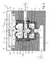
- the gas valve generally designated by reference numeral 1 is in the embodiments of FIGS. 1 and 2 each equipped with only a single valve unit 2, while in the embodiment of the FIG. 3 has several individually operable valve units 2, which are summarized within the gas valve 1 battery-like.
- valve units of the FIG. 3 existing valve units not only as shown in FIG. 2 can correspond to the design shown, but also the design according to FIG. 1 , Of course, at the same time valve units of different types can be used.
- the gas valve 1 has an example block- or plate-shaped main body 3, which receives the respective at least one valve unit 2.
- a one-piece base body 3 can be equipped with several valve units 2 at the same time.
- a segmented structure of the main body is possible, so that each valve unit is assigned its own basic body segment specifically.
- the plurality of valve units 2 expediently strung together in the axial direction of a particular coincident with the longitudinal axis of the main body 3 Aukahungsachse 4.
- Each valve unit 2 has an inlet space 5, which can be connected via an inlet channel 6 extending in the base body 3 to a gas source 7 indicated only schematically.
- a gas source 7 indicated only schematically.
- the inlet spaces 5 of several and in particular all valve units 2 are connected to a common inlet channel 6. In this way, all the inlet spaces 5 can be supplied together and simultaneously with the gas.
- the gas to be controlled by the gas valve 1 is preferably a fuel gas, for example, natural gas, as used in home appliances for heat generation.
- the gas valve 1 could also be used for the control of other gases, for example, to control of compressed air.
- Each valve unit 2 is provided with an outlet space 12, from which an individual outlet channel 13 branches off, which opens out to an outer surface of the main body 3.
- an individual outlet channel 13 branches off, which opens out to an outer surface of the main body 3.
- gas consumers 14 may be connected, for example, gas burners, for example can be summarized in a not shown cooking hob of a cooker.
- each valve unit 2 the inlet space 2 is connected to the outlet space 12 by means of an overflow opening 16.
- the overflow opening 16 is associated with a preferably linear control movement 17 driven valve member 18 which controls the fluid passage through the overflow opening 16.
- the overflow opening 16 is shut off by the valve member 18 and the connection between the inlet chamber 5 and outlet chamber 12 is interrupted.
- this connection is released, it should be mentioned that different open positions are possible, which differ in the size of each released flow cross-section from each other.
- Each valve unit 2 can be operated in the manner of a proportional valve or proportional valve and allows except the closed position, the stepless specification of open positions with diverging flow cross sections of the overflow 16.
- valve concept used in the valve units 2 is that of a poppet valve.
- the valve member 2 has a valve plate 22 which axially opposite a valve seat 23 framing the overflow opening 16, wherein it bears sealingly against the valve seat 23 in the closed position and is lifted more or less far from the valve seat 23 in the open positions.
- each valve unit 2 could directly form the valve housing of each valve unit 2.
- each valve unit 2 is a arranged in the body 3 independent assembly, the manner of a Cartridge is inserted into the base body 3 and is therefore also referred to below as the valve cartridge 65.
- the valve cartridge 65 expediently has a sleeve-shaped valve housing 24 which is separate relative to the main body 3 and is axially inserted with the interposition of one or more annular seals 25 surrounding it in a recess 15 of the main body 3.
- the valve housing 24 includes in axial sequence both the inlet chamber 5 and the outlet chamber 12, wherein the inlet chamber 5 is assigned to a bottom of the receptacle 15 facing rear of the valve housing 24 and is connected via a rear opening 8 of the valve housing 24 with the inlet channel 6 in connection ,
- the opening 8 in the exemplary embodiment passes through an end-side rear wall 9 of the valve housing 24 which is spaced apart by an intermediate wall 10 enclosed by the valve housing 24 at an axial distance from the front side pointing upwards in the drawing.
- the intermediate wall 10 has expediently the shape of an annular disc and has a preferably centrally placed axial opening, which forms the overflow opening 16.
- valve seat 23 which surrounds the overflow opening 16 and faces the rear wall 9, is arranged on the side facing the inlet space 5.
- He is the valve plate 22 axially opposite, which is for example disc-shaped and in particular has a disc-shaped or plate-shaped plate body 19, which may be coated on the valve seat 23 opposite side with an elastomeric material 22.
- the valve disk 22 is located in the inlet space 5.
- the intermediate wall 10 separates the inlet space 5 from the outlet space 12, which is arranged axially spaced apart and likewise enclosed by the valve housing 24.
- a final wall 28 is provided, through which the outlet chamber 12 is permanently sealed gas-tight from a drive chamber 38 in which drivingly with the valve member 18 cooperating drive means 41 are.
- the drive means 41 are of electrically activatable type and expediently consist of at least one piezoactuator 42.
- the drive space 38 adjoins the valve housing 24 on the front side pointing upwards in the drawing and is bounded on the one hand by the main body 3 and on the other by a cover 57 which shields the drive space 38 from the adjacent surroundings. In this way, the drive space 38 is surrounded by wall sections 3, 57 of the gas valve 1. However, there is no gas-tight boundary of the drive space 38. Rather, the drive space 38 is in constant communication with the atmosphere by means of one or more discharge openings 55, so that 38 atmospheric conditions prevail within the drive space. There is a continuous exchange of air between the drive chamber 38 and the surrounding atmosphere possible, wherein the total cross section of the discharge openings 55 is sufficiently large to prevent any accumulation of air within the drive chamber 38.
- a plurality of relief openings 55 are designed directly as wall openings of the cover 57. Additionally or alternatively, at least one relief opening 55 may also be formed by at least one space present between the cover 57 and the main body 3.
- the end wall 28 preferably consists in its entirety of an annular membrane element 34, which has flexible and in particular elastic properties.
- annular membrane element 34 which has flexible and in particular elastic properties.
- it consists of a thin metal or preferably of a material with rubber-elastic properties.
- the membrane element 34 is completely gastight.
- the membrane element 34 is expediently arranged within the valve housing 24, wherein it is fastened in the region of its outer circumference radially inward on the preferably circular contoured side wall 29 of the valve housing 24 with sealing. Attachment means used for this purpose, for example a clamping ring, are indicated at 39.
- annular flexible membrane element 34 is attached to the valve member 18, so that it participates the control movement 17.
- the end wall 28 which is coupled to the movement of the valve member 18, only partially as a flexible membrane element and, moreover, to realize this by means of at least one rigid component.
- the end wall 28 could have a rigid wall section incorporated between the inner circumference 40 and the valve member 18, but which is then also gas-impermeable.
- the annular membrane element 34 essentially extends in a plane perpendicular to the said main axis 35. Between its inner circumference and its outer circumference, the membrane element expediently has at least one curved wall section, as seen in cross-section, the bulge preferably pointing away from the outlet chamber 12.
- the radially outwardly oriented annular outer region 37 of the membrane element 34 forms a relative to the base body 3 stationary section.
- the end wall 2 is deformable in one or the other axial direction due to the flexibility of the diaphragm element 34 in accordance with the control movement 17 of the valve member 18.
- valve member 18 is constantly acted upon in the direction of the closed position.
- the spring device 43 presses the valve disk 22 sealingly against the valve seat 23. In this way it is also ensured that in the event of a malfunction of the drive means 41, the valve member 18 is moved into the closed position for safety's sake.
- the spring device 43 is preferably arranged in the interior of the inlet space 5. Here it is supported at one end on the valve plate 22 and the other end on the rear wall 9.
- the drive means 41 on the part of the valve member 18 cooperate with an actuating portion 44 thereof.
- This actuating portion 44 may in principle be combined with the valve disk 22 in a single component, but in the exemplary embodiment is advantageously a separate component with respect to the valve disk 22.
- the preferably designed in the manner of a plunger operating portion 44 extends from the valve plate 22, the overflow port 16 and then the movable end wall 28, ultimately with its the valve plate 22 opposite end portion 49 hineinzuragen so in the drive chamber 38 that this end portion 49 in the sphere of influence of the drive means 41 comes to rest.
- the drive means 41 forming piezoelectric actuator 42 which is suitably designed as a piezo bending transducer, is supported on the base body 3, wherein only one-sided fixation or, as in the embodiment, a two-sided fixation at axially spaced support points 50 is possible.
- the piezoactuator 42 spans the receptacle 15 in particular web-like manner, wherein it also extends beyond the end section 49 of the actuating section 44.
- the piezoactuator 42 assumes a substantially non-curved extended position and thus makes it possible for the valve member 18 to displace itself to the valve seat 23 until the valve disk 22 abuts. In this way, the closed position is present.
- the piezo actuator 42 bends according to FIG. 1 and pushes on the end portion 49, so that the valve member 18 is moved under execution of a control movement 17 in an open position.
- the electrical activation of the piezoactuator 42 is effected by a control electronics 53 connected to the piezoactuator 42, which is expediently also accommodated in the drive space 38.
- the control electronics 53 can be controlled via an external control panel 54, indicated only schematically, via which the desired operating state can be entered manually.
- the control electronics 53 may be constructed in the form of at least one circuit board, which extends in a plane parallel to the piezoelectric actuator 42.
- the contact region 68 is expediently located on an outer surface of the valve disk 22.
- valve disk 22 align independently of the actuating portion 44 with respect to the valve seat 23 and to abut it fully circumferentially in the closed position.
- the length dimensions of the actuating portion 44 are less than the measured at the contact areas 68, 69 clear distance between the valve plate 22 and the drive means 41 in the deactivated state of the drive means 41. Accordingly, when the drive means 41 is a slight play of movement of the operating portion 44th in the direction of the control movement 17 before or in other words an air gap between on the one hand the actuating portion 44 and on the other hand, the valve plate 22 and / or the drive means 41.
- This measure has, inter alia, the effect that temperature-induced and / or relaxation-induced deformations of particular as Piezoaktuator 42 formed drive means 41 does not express directly in a force exerted on the valve plate 22 actuating force and therefore a said compensating deformation compensating decoupling is given.
- All exemplary embodiments have in common that the drive chamber 38 is separated not only from the hermetically sealed, at least partially from a flexible membrane element 34 end wall 28 of the outlet 12, but in addition also by a partition 46, the end wall 28 in the axial direction of the Main axis 35 is connected in series.
- the partition wall 46 is relative to the main body 3 and the possibly existing valve housing 24 arranged stationary and preferably designed to be rigid overall.
- the aforementioned series connection means that between the outlet space 12 and the drive space 38 in the direction of the control movement 17 successively the end wall 28 and the partition wall 46 are arranged.
- FIGS. 1 and 2 differ in the order of arrangement of the end wall 28 and the partition 46.
- the partition wall 46 and the movable end wall 28 in the direction of the control movement 17 are arranged at a distance from each other, so that between them a chamber is formed, which is referred to as an intermediate chamber 47.
- the intermediate chamber 47 is axially separated on one side by the partition wall 46 from the drive space 38 and axially on the other side by the end wall 28 from the outlet space 12.
- the intermediate chamber 47 is axially separated on the one hand by the end wall 28 from the drive chamber 38 and axially on the other hand by the partition wall 46 from the outlet space 12th
- the intermediate chamber 47 is in constant fluid communication with that space - ie either the drive chamber 38 or the outlet chamber 12 - which is separated by the partition 46 directly from the intermediate chamber 47, ie on the end wall 28th opposite side to the partition 46 connects.
- This constantly communicating connection between the intermediate chamber 47 and the drive chamber 38 (in the embodiment of the FIG. 1 ) or the outlet space 12 (in the embodiment of the FIG. 2 ) is ensured by at least one hereinafter referred to as leakage opening 56 opening, wherein the term leakage opening has been selected to make it clear that said opening allows only a relatively small gas flow rate, so to speak has the function of a throttle opening.
- leakage flow The permissible flow of limited throughput is referred to below as leakage flow.
- the placement of the at least one leakage opening 56 is arbitrary.
- the embodiment realized in the exemplary embodiments is particularly advantageous directly in the dividing wall 46, so that there is a continuous fluid connection between the intermediate chamber 47 and the drive chamber 38 or outlet chamber 12 lying on the other side of the separating chamber 46 through the dividing wall 46.
- the actuating portion 44 slidably passes through a particular centrally arranged passage opening 45 of the partition 46.
- the cross section of the passage opening 45 is slightly larger than the cross section of the actuator 44 in which the passage opening 45 passing through the longitudinal section, so that the mentioned annular gap 58 adjusts with its function as a leakage opening 56.
- This air gap also has the advantage that an extremely smooth mobility of the operating portion 44 is ensured in the axial direction of the main axis 35, while avoiding any adhering effects that could adversely affect the response of the valve member 18 when actuated by the drive means 41.
- each valve unit could also have a plurality of leakage opening 56, but the total cross-section is then so small in total so that only the well-mentioned leakage flow limited throughput is possible.
- the total cross-section of the at least one leakage opening 56 is dimensioned so small that in the case of a leak of the existing in particular of a rubber-elastic material membrane element 34, only a small volume flow of gas from the outlet chamber 12 can pass into the drive chamber 38.
- the leakage opening 56 thus forms a flow limiter.
- the maximum permissible through this volume flow is in particular substantially lower than the maximum allowable overflow opening 16 from the inlet chamber 5 in the outlet chamber 12 per unit of time overflowing gas quantity.
- the leakage opening 56 acts as a flow restrictor or throttle opening.
- the total cross section of the at least one leakage opening 56 is a measure that allows a maximum throughput of about 70 liters of gas per hour at a prevailing in the outlet chamber 12 gas pressure of 150 mbar.
- the entire cross section of the at least one relief opening 55 is considerably larger than the entire cross section of the at least one leakage opening 56. This has the consequence that in a leakage of the end wall 28 per unit time in the drive chamber 38 overflowing gas quantity is substantially less than that amount of gas that can flow out of the drive chamber 38 to the surrounding atmosphere in the same unit of time. Thus, an undesirable volume of gas, possibly ignitable in connection with fuel gas, can not accumulate within the drive space 38 at any time.
- the partition 46 is suitably arranged comparable to the intermediate wall 10 in the interior of the valve housing 24 and secured to the inside of the side wall 29.
- the passage opening 45 is in this case aligned coaxially with the overflow opening 16.
- the intermediate chamber 47 is normally hermetically separated from the adjacent outlet space 12 by the end wall 28. Due to the existing due to the leakage opening 56 continuous fluid connection between the intermediate chamber 47 and the drive chamber 38, prevails in the intermediate chamber 47 normally the same pressure as in the drive chamber 38, which is usually the atmospheric pressure. In the event of leakage of the end wall 28, the gas from the outlet chamber 12 can flow freely into the intermediate chamber 47, but is then largely retained by the partition 46 and can only pass with a harmless flow through the leakage opening 56 into the drive chamber 38. In the embodiment of FIG. 2 Through the leakage opening 56, there is a continuous fluidic connection between the outlet space 12 and the intermediate chamber 48. Thus, in the intermediate chamber 48, the same pressure as in the outlet chamber 12 prevails.
- a drive chamber 38 may be assigned together, which extends over all the valve units 2 away. Accordingly, a single, For example, trough-shaped cover 57 may be present, which is fixed to the base body 3.
- valve cartridge 65 which can be mounted as a unit in the associated receptacle 15 of the main body 3.
- valve cartridge 65 Components of the valve cartridge 65 are in the embodiments at least the valve housing 24, the intermediate wall 10, the end wall 28, the at least one partition 46, the valve member 18 and - if present - the spring means 43.
- the valve cartridge 65 includes in any case also the inlet space 5, the outlet space 12 and the at least one intermediate chamber 48.
- valve cartridge 65 For fixing in the base body 3, the valve cartridge 65 may be pressed with its valve housing 24 in the receptacle 15 or by other, from the drawing not further apparent means, be attached.
- valve cartridge 65 can be checked before insertion into the main body 3 in terms of their functionality and thus allows for errors found a much simpler and cheaper exchange, as if an error would be detected only after installation in the body.
Landscapes
- Engineering & Computer Science (AREA)
- Chemical & Material Sciences (AREA)
- Combustion & Propulsion (AREA)
- Mechanical Engineering (AREA)
- General Engineering & Computer Science (AREA)
- Feeding And Controlling Fuel (AREA)
- Electrically Driven Valve-Operating Means (AREA)
Applications Claiming Priority (1)
| Application Number | Priority Date | Filing Date | Title |
|---|---|---|---|
| DE102009031048A DE102009031048B4 (de) | 2009-06-30 | 2009-06-30 | Gasventil |
Publications (1)
| Publication Number | Publication Date |
|---|---|
| EP2270396A2 true EP2270396A2 (fr) | 2011-01-05 |
Family
ID=42829335
Family Applications (1)
| Application Number | Title | Priority Date | Filing Date |
|---|---|---|---|
| EP10005964A Withdrawn EP2270396A2 (fr) | 2009-06-30 | 2010-06-10 | Soupape à gaz |
Country Status (2)
| Country | Link |
|---|---|
| EP (1) | EP2270396A2 (fr) |
| DE (1) | DE102009031048B4 (fr) |
Cited By (3)
| Publication number | Priority date | Publication date | Assignee | Title |
|---|---|---|---|---|
| IT201800010571A1 (it) * | 2018-11-26 | 2020-05-26 | Sit Spa | Dispositivo per il controllo dell’erogazione di un gas combustibile verso un bruciatore di un apparecchio riscaldatore |
| CN113646961A (zh) * | 2019-02-12 | 2021-11-12 | 雨果-本兹有限两合公司 | 用于降低在室状空腔、如电池块中产生的压力的泄压阀 |
| CN114763857A (zh) * | 2021-01-13 | 2022-07-19 | 浙江三花智能控制股份有限公司 | 一种燃气阀 |
Families Citing this family (2)
| Publication number | Priority date | Publication date | Assignee | Title |
|---|---|---|---|---|
| DE102013212825A1 (de) | 2013-07-01 | 2015-01-08 | Mtu Friedrichshafen Gmbh | Ventileinrichtung, Abgasturbolader, Antriebsvorrichtung |
| DE102013012444A1 (de) * | 2013-07-29 | 2015-01-29 | Astrium Gmbh | Ventilanordnung zum Schalten und/oder Regeln eines Medienstroms eines Raumfahrttriebwerks und Raumfahrttriebwerk |
Citations (4)
| Publication number | Priority date | Publication date | Assignee | Title |
|---|---|---|---|---|
| US2222990A (en) | 1937-12-16 | 1940-11-26 | Honeywell Regulator Co | Motor operated mechanism |
| CH416996A (fr) | 1964-05-22 | 1966-07-15 | Calinter Sa | Dispositif interrupteur de sécurité |
| US3402889A (en) | 1967-06-05 | 1968-09-24 | Robertshaw Controls Co | Flow control systems having combined modulation and pressure regulation of a fluid flow |
| DE102007040698A1 (de) | 2006-09-01 | 2008-07-10 | Indesit Co. S.P.A. | Verfahren zur Steuerung eines Ventils für ein Fluidum und damit ausgestattetes Haushaltsgerät |
-
2009
- 2009-06-30 DE DE102009031048A patent/DE102009031048B4/de not_active Expired - Fee Related
-
2010
- 2010-06-10 EP EP10005964A patent/EP2270396A2/fr not_active Withdrawn
Patent Citations (4)
| Publication number | Priority date | Publication date | Assignee | Title |
|---|---|---|---|---|
| US2222990A (en) | 1937-12-16 | 1940-11-26 | Honeywell Regulator Co | Motor operated mechanism |
| CH416996A (fr) | 1964-05-22 | 1966-07-15 | Calinter Sa | Dispositif interrupteur de sécurité |
| US3402889A (en) | 1967-06-05 | 1968-09-24 | Robertshaw Controls Co | Flow control systems having combined modulation and pressure regulation of a fluid flow |
| DE102007040698A1 (de) | 2006-09-01 | 2008-07-10 | Indesit Co. S.P.A. | Verfahren zur Steuerung eines Ventils für ein Fluidum und damit ausgestattetes Haushaltsgerät |
Cited By (6)
| Publication number | Priority date | Publication date | Assignee | Title |
|---|---|---|---|---|
| IT201800010571A1 (it) * | 2018-11-26 | 2020-05-26 | Sit Spa | Dispositivo per il controllo dell’erogazione di un gas combustibile verso un bruciatore di un apparecchio riscaldatore |
| WO2020109196A1 (fr) * | 2018-11-26 | 2020-06-04 | Sit S.P.A. | Dispositif de régulation d'alimentation en gaz combustible de brûleur d'appareil de chauffage |
| US11988384B2 (en) | 2018-11-26 | 2024-05-21 | Sit S.P.A. | Device for controlling the supply of a combustible gas to a burner of a heating apparatus |
| CN113646961A (zh) * | 2019-02-12 | 2021-11-12 | 雨果-本兹有限两合公司 | 用于降低在室状空腔、如电池块中产生的压力的泄压阀 |
| CN113646961B (zh) * | 2019-02-12 | 2023-11-07 | 雨果-本兹有限两合公司 | 用于降低在室状空腔、如电池块中产生的压力的泄压阀 |
| CN114763857A (zh) * | 2021-01-13 | 2022-07-19 | 浙江三花智能控制股份有限公司 | 一种燃气阀 |
Also Published As
| Publication number | Publication date |
|---|---|
| DE102009031048B4 (de) | 2013-11-28 |
| DE102009031048A1 (de) | 2011-01-05 |
Similar Documents
| Publication | Publication Date | Title |
|---|---|---|
| DE102009031048B4 (de) | Gasventil | |
| DE102018131086A1 (de) | Motorbetätigtes Ventil | |
| EP2237128B1 (fr) | Agencement de vanne de pression proportionnelle avec pré-contrôle commandé par un dispositif de régulation électronique | |
| EP2971963B1 (fr) | Ensemble de soupapes à gaz | |
| DE102008050252B4 (de) | Ventilvorrichtung für Brennkraftmaschinen, insbesondere Sekundärluftventil | |
| EP2619504B1 (fr) | Structure d'un ensemble de vannes à gaz | |
| DE102007062207A1 (de) | Pneumatischer Verstärker und Anordnung zum Stellen einer Stellarmatur einer verfahrenstechnischen Anlage | |
| EP3087279B1 (fr) | Ensemble de soupapes | |
| DE102007012729B3 (de) | Dosierventil für Atemgas | |
| DE2826538C2 (fr) | ||
| DE102009031047B4 (de) | Gasventil | |
| DE19912334C2 (de) | Vorsteuereinrichtung | |
| DE102008056751A1 (de) | Fluidikvorrichtung mit normal-geschlossener Durchlassöffnung | |
| DE10200273A1 (de) | Elektrisch gesteuertes Gasventil | |
| DE2921561C2 (de) | Beatmungsventil | |
| DE10152414A1 (de) | Hydraulikzylinder | |
| AT366803B (de) | Absperr- und regelventil | |
| EP0866394B1 (fr) | Régulateur pour installations de production d'air comprimé dans des véhicules | |
| DE19932139B4 (de) | Vorgesteuertes Schieberventil | |
| DE102011053152A1 (de) | Vorrichtung zur Steuerung der Brennstoffmenge durch eine Brennstoffleitung | |
| DE10107868A1 (de) | Pneumatisches Wegeventil | |
| DE10148384B4 (de) | Sekundärluftventil | |
| DE102021114426A1 (de) | Leckagedetektion | |
| DE102015223943B4 (de) | Druckregelvorrichtung | |
| DE2719523C3 (de) | Gasventil |
Legal Events
| Date | Code | Title | Description |
|---|---|---|---|
| PUAI | Public reference made under article 153(3) epc to a published international application that has entered the european phase |
Free format text: ORIGINAL CODE: 0009012 |
|
| AK | Designated contracting states |
Kind code of ref document: A2 Designated state(s): AL AT BE BG CH CY CZ DE DK EE ES FI FR GB GR HR HU IE IS IT LI LT LU LV MC MK MT NL NO PL PT RO SE SI SK SM TR |
|
| AX | Request for extension of the european patent |
Extension state: BA ME RS |
|
| STAA | Information on the status of an ep patent application or granted ep patent |
Free format text: STATUS: THE APPLICATION IS DEEMED TO BE WITHDRAWN |
|
| 18D | Application deemed to be withdrawn |
Effective date: 20140103 |