EP2271261B1 - Verfahren zur probenahme- und abgabe - Google Patents
Verfahren zur probenahme- und abgabe Download PDFInfo
- Publication number
- EP2271261B1 EP2271261B1 EP09725660.6A EP09725660A EP2271261B1 EP 2271261 B1 EP2271261 B1 EP 2271261B1 EP 09725660 A EP09725660 A EP 09725660A EP 2271261 B1 EP2271261 B1 EP 2271261B1
- Authority
- EP
- European Patent Office
- Prior art keywords
- sampler
- passage
- sample
- penetrable
- container
- Prior art date
- Legal status (The legal status is an assumption and is not a legal conclusion. Google has not performed a legal analysis and makes no representation as to the accuracy of the status listed.)
- Active
Links
Images




Classifications
-
- B—PERFORMING OPERATIONS; TRANSPORTING
- B01—PHYSICAL OR CHEMICAL PROCESSES OR APPARATUS IN GENERAL
- B01L—CHEMICAL OR PHYSICAL LABORATORY APPARATUS FOR GENERAL USE
- B01L3/00—Containers or dishes for laboratory use, e.g. laboratory glassware; Droppers
- B01L3/02—Burettes; Pipettes
- B01L3/0282—Burettes; Pipettes mounted within a receptacle
-
- A—HUMAN NECESSITIES
- A61—MEDICAL OR VETERINARY SCIENCE; HYGIENE
- A61B—DIAGNOSIS; SURGERY; IDENTIFICATION
- A61B10/00—Instruments for taking body samples for diagnostic purposes; Other methods or instruments for diagnosis, e.g. for vaccination diagnosis, sex determination or ovulation-period determination; Throat striking implements
- A61B10/0045—Devices for taking samples of body liquids
-
- A—HUMAN NECESSITIES
- A61—MEDICAL OR VETERINARY SCIENCE; HYGIENE
- A61B—DIAGNOSIS; SURGERY; IDENTIFICATION
- A61B5/00—Measuring for diagnostic purposes; Identification of persons
- A61B5/15—Devices for taking samples of blood
- A61B5/150007—Details
- A61B5/150015—Source of blood
- A61B5/150022—Source of blood for capillary blood or interstitial fluid
-
- A—HUMAN NECESSITIES
- A61—MEDICAL OR VETERINARY SCIENCE; HYGIENE
- A61B—DIAGNOSIS; SURGERY; IDENTIFICATION
- A61B5/00—Measuring for diagnostic purposes; Identification of persons
- A61B5/15—Devices for taking samples of blood
- A61B5/150007—Details
- A61B5/150206—Construction or design features not otherwise provided for; manufacturing or production; packages; sterilisation of piercing element, piercing device or sampling device
- A61B5/150213—Venting means
-
- A—HUMAN NECESSITIES
- A61—MEDICAL OR VETERINARY SCIENCE; HYGIENE
- A61B—DIAGNOSIS; SURGERY; IDENTIFICATION
- A61B5/00—Measuring for diagnostic purposes; Identification of persons
- A61B5/15—Devices for taking samples of blood
- A61B5/150007—Details
- A61B5/150206—Construction or design features not otherwise provided for; manufacturing or production; packages; sterilisation of piercing element, piercing device or sampling device
- A61B5/150236—Pistons, i.e. cylindrical bodies that sit inside the syringe barrel, typically with an air tight seal, and slide in the barrel to create a vacuum or to expel blood
-
- A—HUMAN NECESSITIES
- A61—MEDICAL OR VETERINARY SCIENCE; HYGIENE
- A61B—DIAGNOSIS; SURGERY; IDENTIFICATION
- A61B5/00—Measuring for diagnostic purposes; Identification of persons
- A61B5/15—Devices for taking samples of blood
- A61B5/150007—Details
- A61B5/150206—Construction or design features not otherwise provided for; manufacturing or production; packages; sterilisation of piercing element, piercing device or sampling device
- A61B5/150244—Rods for actuating or driving the piston, i.e. the cylindrical body that sits inside the syringe barrel, typically with an air tight seal, and slides in the barrel to create a vacuum or to expel blood
-
- A—HUMAN NECESSITIES
- A61—MEDICAL OR VETERINARY SCIENCE; HYGIENE
- A61B—DIAGNOSIS; SURGERY; IDENTIFICATION
- A61B5/00—Measuring for diagnostic purposes; Identification of persons
- A61B5/15—Devices for taking samples of blood
- A61B5/150007—Details
- A61B5/150206—Construction or design features not otherwise provided for; manufacturing or production; packages; sterilisation of piercing element, piercing device or sampling device
- A61B5/150251—Collection chamber divided into at least two compartments, e.g. for division of samples
-
- A—HUMAN NECESSITIES
- A61—MEDICAL OR VETERINARY SCIENCE; HYGIENE
- A61B—DIAGNOSIS; SURGERY; IDENTIFICATION
- A61B5/00—Measuring for diagnostic purposes; Identification of persons
- A61B5/15—Devices for taking samples of blood
- A61B5/150007—Details
- A61B5/150343—Collection vessels for collecting blood samples from the skin surface, e.g. test tubes, cuvettes
-
- A—HUMAN NECESSITIES
- A61—MEDICAL OR VETERINARY SCIENCE; HYGIENE
- A61B—DIAGNOSIS; SURGERY; IDENTIFICATION
- A61B5/00—Measuring for diagnostic purposes; Identification of persons
- A61B5/15—Devices for taking samples of blood
- A61B5/150007—Details
- A61B5/150351—Caps, stoppers or lids for sealing or closing a blood collection vessel or container, e.g. a test-tube or syringe barrel
-
- A—HUMAN NECESSITIES
- A61—MEDICAL OR VETERINARY SCIENCE; HYGIENE
- A61B—DIAGNOSIS; SURGERY; IDENTIFICATION
- A61B5/00—Measuring for diagnostic purposes; Identification of persons
- A61B5/15—Devices for taking samples of blood
- A61B5/150007—Details
- A61B5/150755—Blood sample preparation for further analysis, e.g. by separating blood components or by mixing
-
- B—PERFORMING OPERATIONS; TRANSPORTING
- B01—PHYSICAL OR CHEMICAL PROCESSES OR APPARATUS IN GENERAL
- B01L—CHEMICAL OR PHYSICAL LABORATORY APPARATUS FOR GENERAL USE
- B01L3/00—Containers or dishes for laboratory use, e.g. laboratory glassware; Droppers
- B01L3/02—Burettes; Pipettes
- B01L3/021—Pipettes, i.e. with only one conduit for withdrawing and redistributing liquids
- B01L3/0217—Pipettes, i.e. with only one conduit for withdrawing and redistributing liquids of the plunger pump type
- B01L3/022—Capillary pipettes, i.e. having very small bore
-
- A—HUMAN NECESSITIES
- A61—MEDICAL OR VETERINARY SCIENCE; HYGIENE
- A61B—DIAGNOSIS; SURGERY; IDENTIFICATION
- A61B10/00—Instruments for taking body samples for diagnostic purposes; Other methods or instruments for diagnosis, e.g. for vaccination diagnosis, sex determination or ovulation-period determination; Throat striking implements
- A61B10/0045—Devices for taking samples of body liquids
- A61B10/0051—Devices for taking samples of body liquids for taking saliva or sputum samples
-
- A—HUMAN NECESSITIES
- A61—MEDICAL OR VETERINARY SCIENCE; HYGIENE
- A61B—DIAGNOSIS; SURGERY; IDENTIFICATION
- A61B10/00—Instruments for taking body samples for diagnostic purposes; Other methods or instruments for diagnosis, e.g. for vaccination diagnosis, sex determination or ovulation-period determination; Throat striking implements
- A61B10/0045—Devices for taking samples of body liquids
- A61B2010/0067—Tear or lachrymal fluid
-
- A—HUMAN NECESSITIES
- A61—MEDICAL OR VETERINARY SCIENCE; HYGIENE
- A61J—CONTAINERS SPECIALLY ADAPTED FOR MEDICAL OR PHARMACEUTICAL PURPOSES; DEVICES OR METHODS SPECIALLY ADAPTED FOR BRINGING PHARMACEUTICAL PRODUCTS INTO PARTICULAR PHYSICAL OR ADMINISTERING FORMS; DEVICES FOR ADMINISTERING FOOD OR MEDICINES ORALLY; BABY COMFORTERS; DEVICES FOR RECEIVING SPITTLE
- A61J1/00—Containers specially adapted for medical or pharmaceutical purposes
- A61J1/14—Details; Accessories therefor
- A61J1/20—Arrangements for transferring or mixing fluids, e.g. from vial to syringe
- A61J1/2093—Containers having several compartments for products to be mixed
-
- A—HUMAN NECESSITIES
- A61—MEDICAL OR VETERINARY SCIENCE; HYGIENE
- A61M—DEVICES FOR INTRODUCING MEDIA INTO, OR ONTO, THE BODY; DEVICES FOR TRANSDUCING BODY MEDIA OR FOR TAKING MEDIA FROM THE BODY; DEVICES FOR PRODUCING OR ENDING SLEEP OR STUPOR
- A61M5/00—Devices for bringing media into the body in a subcutaneous, intra-vascular or intramuscular way; Accessories therefor, e.g. filling or cleaning devices, arm-rests
- A61M5/178—Syringes
- A61M5/28—Syringe ampoules or carpules, i.e. ampoules or carpules provided with a needle
- A61M5/281—Syringe ampoules or carpules, i.e. ampoules or carpules provided with a needle using emptying means to expel or eject media, e.g. pistons, deformation of the ampoule, or telescoping of the ampoule
- A61M5/283—Syringe ampoules or carpules, i.e. ampoules or carpules provided with a needle using emptying means to expel or eject media, e.g. pistons, deformation of the ampoule, or telescoping of the ampoule by telescoping of ampoules or carpules with the syringe body
-
- B—PERFORMING OPERATIONS; TRANSPORTING
- B01—PHYSICAL OR CHEMICAL PROCESSES OR APPARATUS IN GENERAL
- B01L—CHEMICAL OR PHYSICAL LABORATORY APPARATUS FOR GENERAL USE
- B01L2300/00—Additional constructional details
- B01L2300/04—Closures and closing means
- B01L2300/041—Connecting closures to device or container
- B01L2300/044—Connecting closures to device or container pierceable, e.g. films, membranes
-
- B—PERFORMING OPERATIONS; TRANSPORTING
- B01—PHYSICAL OR CHEMICAL PROCESSES OR APPARATUS IN GENERAL
- B01L—CHEMICAL OR PHYSICAL LABORATORY APPARATUS FOR GENERAL USE
- B01L2300/00—Additional constructional details
- B01L2300/06—Auxiliary integrated devices, integrated components
- B01L2300/0672—Integrated piercing tool
-
- B—PERFORMING OPERATIONS; TRANSPORTING
- B01—PHYSICAL OR CHEMICAL PROCESSES OR APPARATUS IN GENERAL
- B01L—CHEMICAL OR PHYSICAL LABORATORY APPARATUS FOR GENERAL USE
- B01L2400/00—Moving or stopping fluids
- B01L2400/04—Moving fluids with specific forces or mechanical means
- B01L2400/0403—Moving fluids with specific forces or mechanical means specific forces
- B01L2400/0406—Moving fluids with specific forces or mechanical means specific forces capillary forces
-
- B—PERFORMING OPERATIONS; TRANSPORTING
- B01—PHYSICAL OR CHEMICAL PROCESSES OR APPARATUS IN GENERAL
- B01L—CHEMICAL OR PHYSICAL LABORATORY APPARATUS FOR GENERAL USE
- B01L2400/00—Moving or stopping fluids
- B01L2400/04—Moving fluids with specific forces or mechanical means
- B01L2400/0475—Moving fluids with specific forces or mechanical means specific mechanical means and fluid pressure
- B01L2400/0478—Moving fluids with specific forces or mechanical means specific mechanical means and fluid pressure pistons
Definitions
- the present invention relates to a device for dispensing a sample and method for dispensing samples to be analysed.
- the present invention also provides means for mixing a sample, reagent and a fluid stored in a sealed chamber in addition to a volumetric dispensing of the sample diluted to a predetermined concentration.
- US 3,233,785 describes a very basic and simple rinsing pipette, wherein a blood sample flows upwardly in a capillary by capillary attraction and automatically stops when reaching a chamber substantially wider in diameter than the capillary passage.
- US 3,453,941 discloses an apparatus for determining the blood group of a specimen comprising means for collecting, reagent availability in a container, mixing means and means to deposit the sample to a viewing plate.
- a diluter which provide for the aspiration of a predetermined quantity of a sample liquid followed by discharge of the sample together with a predetermined quantity of diluent is disclosed in US 3,869,068 .
- US 4,003,262 discloses an apparatus for measuring precise micro quantities of fluid samples wherein the self-filling capillary tube is open to atmosphere through an opening in the closed end of the shield.
- US 4,396,024 discloses a device for extraction of capillary blood, a holder integrally connected thereto and a closure pin at the rear end of the capillary.
- US 4,589,421 Another type of a sampling device is disclosed in US 4,589,421 wherein the invention allows sampling without mechanical movement and dispensing of a precise amount of sample by means of mechanical movement.
- the sampling device as disclosed in US 4,589,421 may also be an integral part of the test device.
- US 4,690,005 discloses a dosage device by means of which it is possible to take a sample out of a liquid to mix the sample into a dilution liquid, e.g. a reagent, in a precise proportion, and to dose the mixture into another vessel e.g. a test tube or measurement vessel.
- a dilution liquid e.g. a reagent
- the invention of US 5,833,630 relates to a sample collection device to collect capillary blood.
- the sample is absorbed by capillary action of a capillary positioned into a holder producing a closure means of a reagent liquid containing cuvette into which the sample is transferred for analyzes.
- a protective and pressure cap can be applied to the free end of the capillary. A downward movement of the pressure cap releases the sample into the cuvette, thereafter the sample is conveyed to the analyzer.
- a further invention disclosing a method and kit for collecting samples of liquid specimens for analytical testing is disclosed in US 5,935,864 wherein said method comprises a sample container and a reagent vial.
- the sample and the reagent in the reagent vial are drawn by capillary attraction into the chamber containing a test strip.
- a sample means and system for testing a sample liquid disclosing the same principle as in US 5,935,864 is disclosed in US 2005/0145046 .
- Said US application provides a sampling means with a reservoir for a dilution liquid and/or reaction liquid. The method enables delivery of sample liquid and the dilution and/or reaction liquid in succession or at the same time, especially by a single actuation of the sampling means.
- US 6,803,021 Bl relates to a device for receiving and discharging a given amount of liquid.
- the sample is aspired by capillary attraction while the air escapes via an aperture.
- the aperture is closed and pressure is directed on the flexible bellows.
- US 6,803,021 B1 further discloses an agitating means comprising a hook-like continuation which effectively stirs the liquid with a reagent in a test tube.
- WO 2005/071388 discloses a sampling and assay device comprising a multi chamber assay format for swab sampling wherein needed reagents and liquid medium is available in said chambers of the assay device.
- the chambers are separated from each other by membranes which are punctured either by the sampling swab or a puncturing means. When applying a puncturing means the membranes are ruptured by relative movement of at least two parts of the assay device.
- CH-384,899 discloses a method of drawing and dispensing a liquid sample using a device that comprises a container comprising a sealed chamber bounded on at least one side by a penetrable member, said sealed chamber containing a fluid, and a sampling device comprising a sampler defining a passage which is open at both ends, at least a portion of the passage extending from a first end comprising a capillary passage, the sampling device also having a sleeve that acts as a penetrating means.
- the method comprises: penetrating the penetrable member with said penetrating means; removing the sampler from the sampling device and drawing a liquid sample into the capillary passage by capillary action; inserting the outer end of the sampler into the chamber; expelling the liquid sample into the chamber by creating a negative pressure in the chamber; mixing the sample with the fluid in the chamber; separating the sampler and reattaching it to the sealed chamber so that the inner end of the capillary passage communicates with the interior of the sealed chamber; and expelling the mixed liquid sample and fluid through said capillary passage.
- the present invention provides a volumetric dilution of a volumetric sample with a predetermined volume of e.g. a buffer or fluid comprising one or more reagents or any other fluid followed by a volumetric dispensing and mixing of said sample-diluent composition wherein the level of volumetric dilution and dispensing is predetermined.
- a volumetric dilution of a volumetric sample with a predetermined volume of e.g. a buffer or fluid comprising one or more reagents or any other fluid followed by a volumetric dispensing and mixing of said sample-diluent composition wherein the level of volumetric dilution and dispensing is predetermined.
- a method of drawing and dispensing a liquid sample using a device that comprises a container comprising a sealed chamber bounded on at least one side by a penetrable member, said sealed chamber containing a fluid, and a sampling device comprising a sampler defining a passage which is open at both ends, at least a portion of the passage extending from a first end comprising a capillary passage, the sampler having a penetrating means at a second end, said method comprising: drawing a liquid sample into said capillary passage by capillary action; penetrating said penetrable member with said penetrating means such that said passage containing the liquid sample is in communication with said sealed chamber; and operating said penetrable member as a piston to expel the fluid out of the sealed chamber and into the sampler and simultaneously to expel said liquid sample out of the sampler through said first end of said passage, followed by said fluid.
- the capillary passage operates to draw samples into the capillary passage by capillary action. Once a sample has been taken the penetrating means can penetrate the penetrable member. As the sampler passes further into the sealed chamber the contents of the sealed chamber can be dispensed out of the sealed chamber and into the sampler. Simultaneously the sample will be dispensed out of the sampler, followed by, and mixed with, any liquid originally stored in the sealed chamber. Very efficient mixing can be performed by a vigorous vortex formed into the liquids which are dispended from the sampling device.
- a method of drawing and dispensing a liquid sample using a device that comprises a container comprising a sealed chamber bounded on at least one side by a penetrable member, said sealed chamber containing a fluid, and a sampling device comprising a sampler defining a passage which is open at both ends, at least a portion of the passage extending from a first end comprising a capillary passage, the sampler having a penetrating means at a second end, said method comprising: drawing a liquid sample into said capillary passage by capillary action; penetrating said penetrable member with said penetrating means such that said passage containing the liquid sample is in communication with said sealed chamber; operating said penetrable member as a piston to expel said liquid sample into said chamber; mixing said liquid sample with said fluid in said chamber; and operating said penetrable member as a piston to expel the mixed liquid sample and fluid through said passage.
- the invention comprises a method wherein a penetrable member expels the content of the passage when operating as a piston. It expels the content of the passage either into the sealed chamber or the content of the sealed chamber out through said passage. Furthermore, the passage is emptied by expelling the content of the passage through the first end of the passage.
- Said container may be of any shape, preferably cylinder shaped, and size intended for clinical or hygiene tests.
- the term container is defined to enclose any vessel e.g. test tube, vial or alike.
- the penetrable member is a puncturable member and the penetrating means comprises a puncturing means.
- the puncturable member is punctured by the puncturing means.
- the penetrable member comprises a member with an aperture, the penetrating means comprising a plug which is arranged to seal the aperture.
- the penetrating means comprising the plug is pushed through the aperture so the passage is in fluid communication with the sealed chamber.
- the penetrable member comprises a member having an aperture, the device further comprising a plug which is arranged to seal the aperture.
- the penetrating means pushes the plug through the aperture to access the contents of the sealed chamber.
- the sampler may be configured to slide inside the container and may comprise a protrusion arranged to abut against the walls of the container and limit penetration of the sampler into the container. Once the sampler has penetrated further into the container the protrusion abuts against the container to prevent further penetration.
- the protrusion is preferably arranged at or near the first end of the sampler and can thus additionally be used to support or rest against an auxiliary vessel into which the sample may be dispensed.
- the first end of the sampler may be inside the auxiliary vessel and form a closed system. This prevents the release of potentially infectious material from the apparatus.
- the first end of the sampler may be designed to tightly fit to the opening of the reaction vessel to prevent any leakage from either the device or auxiliary vessel.
- the auxiliary vessel may have the shape and function, but is not limited to, of a test tube, cuvette, cassette, lateral flow or flow through assay device.
- the volume of the sample to be taken may be controlled by the volume of the capillary passage.
- the capillary passage At the end of the capillary passage there may be a stepping zone in which the diameter of the hollow passage increases in a step wise fashion being > 1.5 mm, usually 1 to 6 mm and preferably 2 to 3 mm.
- the volume of liquid drawn is limited by the volume of the capillary passage.
- the diameter of the passage At the other end of the passage from the capillary passage the diameter of the passage is preferably greater than the capillary passage.
- a marked line on the capillary may be used to indicate the volume of the sample drawn into the capillary.
- the sampler may comprise engagement means spaced apart from the second end of the sampler and configured to engage with the penetrable member after penetrating the penetrable member.
- the penetrable member may be movable and the engagement means configured to operate the penetrable member as a piston or plunger. The penetrable member thus moves simultaneously with the sampler as it penetrates further into the container. The volume of the sealed chamber thus decreases and any contained fluid is dispensed. To provide a good seal between the penetrable member and the sampler the penetrable member is preferably elastic.
- At least one ventilation opening may be provided between the inside and outside of the container, the ventilation opening being arranged outside the sealed chamber.
- the ventilation means may conveniently be arranged in a flange configured to engage with the penetrable member after penetrating the penetrable member.
- the flange may contain at least one opening for ventilation. If the flange comprises several openings they are distributed either uniformly or irregularly through the flange.
- the opening may have any shape and size. Most preferably the opening is round having a diameter of 0.1 to 1.5 mm, preferably 0.2 to 0.3 mm. If located at the edge of the flange the shape of the opening may be half circled or alike.
- the container may further comprise a second sealed chamber bounded on at least one side by a second penetrable member.
- the penetrating means will first penetrate the first penetrable member and the fluid contained in the first sealed chamber is dispensed.
- the penetrating means is inserted further into the container and the second penetrable member penetrated the fluid contained in the second sealed chamber is dispensed.
- the sampler may be configured to store dry reagents in the passage.
- the dry reagents are preferably stored within the non-capillary part of the passage. As the liquid from the sealed chamber is dispensed it thus automatically mixes with the dry reagents to form the required assay.
- the device may comprise at least one flange and/or at least one fluke and its counterpart.
- the penetrable member may be cylinder shaped and correspond to a stopper which abuts the walls of said container and has a liquid and gas tight friction contact with said walls.
- An advantage of the present invention is to combine a capillary sampler and one or more additional reagents provided in one or more sealed chambers into one easily operational unit. Those additional reagents can be in solid, liquid and gas form.
- specimen to be analysed are, but not limited to, blood, serum, plasma, saliva, urine, sputum, sweat, tears, cerebrospinal fluid and other body fluids of human or animal origin.
- Typical specimens are samples especially from open sites like blood drops from finger pricks, saliva from mouth, tears from eyes and open laboratory containers like test tubes.
- the fluid with which the sample is mixed is usually a buffer needed for the assay.
- the present invention enables simple mixing of the sample with assay reagents for further performance of chemical, biochemical or biomedical qualitative or quantitative assays. It is also possible to use the device for hygiene sampling of industrial water processing, dairy, beverages, cosmetics, determining hygiene of laboratory and surgical spaces and alike.
- the present invention is designed to collect exact volumetric liquid samples, like blood, serum, plasma saliva, urine, sputum, sweat, tears, cerebrospinal fluid or other body fluids and liquids in open containers or any hygiene samples, and to dilute those samples and mix them with auxiliary reagents and finally dispense the obtained mixture to perform analytical tests, respectively.
- the dispensing device comprises according to the invention a plurality of parts.
- the first mechanical part is a sampler which constitutes sample collection and dispensing means which defines a passage open at both ends, the passage comprising a capillary tube or passage 27 extending along a portion of the passage.
- the capillary passage is a single hollow means allowing volumetric capillary passage between capillary opening 5 and stepping zone 6, only. Volumetric sampling of liquids takes place by capillary action and the dispensing of both liquids and gases takes place by using positive, preferably manual pressure.
- the stepping zone 6 allows passage of gases and liquids in both directions, however the stepping zone 6 stops the capillary action of the fluid when the inner diameter of 0.1 mm extends to ⁇ 2.0 mm of the hollow construction e.g. the capillary gets larger by the clear cut step 7.
- the dimensionally larger ⁇ 1.5 mm (1 to 6 mm) end of the sampler comprises penetrating means, 9 with a single opening 8 or multiple openings as illustrated in FIGS. 16 and 17 , respectively.
- the penetrating means form a sharp end or puncturing means, 9.
- FIG 16 depicts a penetrating means in which the puncturing means is formed by the rim of the passage of the sampler.
- This puncturing means 9 is especially designed to efficiently puncture elastic materials while keeping the passage open for gases and liquids.
- the sampler 1 which comprises the wider ⁇ 1.5 mm (1 to 6 mm) hollow construction 10, which is substantially wider than the preceding narrow hollow construction (allowing capillary action) allows gases and liquids to pass through.
- This wide hollow construction 10 is specially designed to be a storage space for possible additional dry reagents 13 needed for the assay.
- This wide hollow construction 10 is located between the stepping zone 6 and the opening 8.
- Flanges 11, form engagement means and guide the movement of sampler 1 and act as an engagement means for the sampler 1 to move or change position inside the container 2.
- the flanges 11 are preferably circular or of sectorial or of any other form.
- the flukes 31 and its counterparts 32 of the sampler 1 are designed to catch the sampler 1 with penetrable member 3, hence forming one combined moving unit 1, 3.
- the sampler 1 and penetrable means 3 and 4 are caught by an engagement means further comprising a fluke 31 and its counterpart 32.
- Said engagement means is configured to operate the penetrable member as a piston by either pushing or pulling said penetrable member.
- the penetrable member is slidable within the container and the combined moving unit may thus act as a piston to expel contents of a chamber into the passage.
- Flanges 11 contain ventilation holes 14 which are needed for air or gas to escape during sampling and penetrating of the penetrable members 3, 4.
- Flange 11 guides and supports the movement of sampler 1 inside the container 2 during sampling and dispensing actions.
- Flange 11 is spaced apart from the end of the sample.
- the fluke 31 and its counterpart may form a locking mechanism in which the sampler 1 may be unlocked from the penetrable member by twisting sampler 1 in one direction.
- the container 2 forms a gas-and-liquid-tight cylinder and has contained in it one or more penetrable members.
- the penetrable members 3, 4 of the invention are elastic members which operate as stoppers.
- Penetrable member 3 is preferably cylinder shaped, wherein the walls of the penetrable member are against the wall of the container 2 and wherein one end of the penetrable member comprises a penetrable elastic membrane and wherein the other end is open. Said open end hides a sharp end of a penetrating means which is fixed to a shaft, wherein said penetrating means and shaft comprise at least one flange and at least one fluke which catch the shaft to the cylinder shaped penetrable member.
- the penetrable member becomes a piston when the shaft or rod comprising a penetrating means has been caught onto the penetrable member.
- When caught a back or forth movement is enabled creating either a positive or a negative pressure in a vessel comprising said penetrable member.
- the penetrating means is hollow and forms part of the passage.
- the container 2 constitutes a cylinder, which is open at the first (proximal) end 26 and closed at the second (distal) end 17.
- the container preferably has a uniform cross-section but is not limited to cylinders having a circular cross-section.
- the at least one opening 14 in the wall of the container 2 is an option for ventilation, escape and substitute, of air or gases between the external and internal spaces of the container 2. As described earlier, other options for ventilation are the ventilation holes 14 in the flange 11 of the sampler 1.
- the container 2 contains either one or more chambers, 15, 16 (also known as sealed chambers) forming volumetric compartments for storing the gas or liquid reagents 15a and 16a needed in analytical assays, respectively.
- the non limiting example above discloses one chamber 15 or two chambers 15 and 16. This is an example only and it is understood that the spirit and scope of the present invention covers also a device comprising a plurality of chambers designed by a similar operational principle.
- the penetrable members 3, 4 form elastic members which are puncturable by the sharp edge 9.
- a penetrable members 4 and its use is illustrated in FIGS. 3, 4 , 8, 9, 10 and 11 , respectively.
- the elastic member may act as a piston, stopper or plunger. After being punctured, the puncturable member forms a seal preferably with the sharp edge 9 of the sampler.
- the penetrable member is not limited to said embodiment. It may also comprise a member with an aperture, wherein the member is seal tight and prevents any leakage by the use of a plug.
- the advantage of a member with an aperture is that it enables the use of a blunt penetrating means. Moreover, it is easier to enter the chamber through a member with an aperture since the member will not stretch at penetration. Accordingly, the penetrating means does not necessarily comprise a sharp edge but the shape can be more or less blunt.
- FIG. 22 and 23 An additional embodiment of the invention is illustrated in detail in figures 22 and 23 .
- a plug 33 forms the penetrating means and the penetrable elastic member 3 comprises an aperture or opening which is liquid tight and seal tight plugged by plug 33.
- liquid or gas reagents 15a of the closed volumetric chamber 15 passes to the passage through the openings 52 located in the side wall of the sampler 1.
- the passage is in fluid communication with the sealed chamber when the plug 33 is pushed into the volumetric chamber 15 containing either liquid reagent or gas 15a by means of an opposite movement of container 2 and the sampler.
- the sampler comprises at least one opening 52 at the second end of the the sampler such that the sampler defines a passage between the first end and the second end of the sampler.
- the plug 33 is leakage tight and seal tight by friction contact with the penetrable member 3. When the container 2 is pressed downwards towards the sampler the plug is pushed through the aperture and the passage into the chamber is opened through openings 52.
- the described second embodiment is also applicable to a sample collection and dispensing device comprising more than one chamber. Said modifications can be achieved for example by exploiting the learning of the present invention e.g. by arranging an additional plug in an aperture of the additional penetrable member.
- the plug does not form part of the penetrating means.
- the plug is arranged in the aperture of the penetrable member and the penetrating means are used to push the plug through the aperture.
- the edge of the penetrating means pushes the plug 33 into the chamber 15.
- the density of plug 33 can be chosen to be smaller than that of the fluid 15a in the chamber 15 enabling the plug 33 to float away from the aperture 8 and, accordingly, allow the passage of the sampler to be in fluid communication with the sealed chamber.
- the penetrable members 3 and 4 limit and determine the volume of chambers 15 and 16 in relation to each other and also in combination with the walls and closed second (distal) end 17 of the container 2.
- the penetrable members 3 and 4 act as stationary stoppers during storage of reagent containing medium, gases or liquids in said chamber.
- the distal end 28 of the sharp end 9 of the sampler 1 rests inside the penetrable members 3 in space 19, especially designed for free escape of air or gases from the capillary tube 27 of the sampler 1 during sampling.
- the distal end 28 of the sharp end 9 of the sampler 1 penetrates the penetrable members 3 and 4 forcing them to move as plungers/pistons 3 and 4.
- fluke 31 In addition to penetration of the penetrable members 3 and 4 with the distal end 28 of the sharp end 9 of the sampler 1, fluke 31 catches its counterpart 32 and flange 11 engages penetrable member 3 to form an engagement means of the sampler 1. Pressure is applied to the sampler 1 and this movement drains reagent medium, gases and/or liquids volumetrically from chambers 15 and 16. An exact volumetric amount of said gases or liquids which is dispensed out from device is determined by the length of the movement of said penetrable members 3 and 4 inside the predetermined chambers 15 and 16 of said container 2.
- the device of the present invention comprises features wherein the volumetric sample is obtained by the sampler comprising a capillary tube with one open end 5 for sampling and another end comprising a stepping zone 6 which is wider than the diameter of the capillary.
- the capillary action ceases when the sample reaches the stepping zone.
- the volumetric dilution and dispensing of the sample rely on diluting the sample with a predetermined volume of liquid and dispensing of a predetermined volume of said sample-fluid composition.
- Said device of the present invention is disclosed in detail elsewhere in the specification.
- the device comprises a sampler 1, at least one penetrable member 3 which preferably is a cylinder shaped stopper with one open end comprising a preferably central passage and one closed end, one or more protruding flanges 11 and one or more flukes 31 positioned on the passage and fluke counterpart(s) 32 in the inner wall of the open end of the penetrable member.
- the sampler 1 defines a passage which comprises a hollow construction 10 with a penetrating means 9.
- the flukes and their counterparts and the flanges and stopper are embodiments enabling volumetric dilution and volumetric dispensing.
- the dilution of the sample can be regulated according to the needs and to equal with a predetermined diluent volume.
- the volumetric volume to be dispensed may be regulated by the same features i.e. by choosing the proper positioning of the fluke(s), flange(s) and stopper and, accordingly, the position at which they catch.
- said proper positioning may be fixed according to needs.
- the advantage of a regulated dilution is that the chamber(s) can be overfilled with diluent to avoid that the loss of diluent due to evaporation during storage will disable the assay. Said feature extends the shelf life of the device.
- An efficient mixing of the sample and the reagents can also be performed by using negative pressure for passing the sample into the chamber. This action is followed by the use of positive pressure, which forces the sample and the reagent mixture out of the device through the sampler. Also several back and forth movements of the liquid can be used in order to facilitate the mixing of different reaction components.
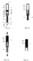
- FIGS. 5-7 show schematically in cross-section the procedure for sampling, diluting, mixing and dispensing the sample 21, one or several dried reagent(s) 13 and a liquid reagent 15a.
- the reagent may comprise one or several reagent(s) or a reagent free buffer. According to the invention this can be achieved in only two simple sequential steps using a container containing one volumetric chamber 15.
- the first step collects the volumetric sample from a drop of whole blood 21 by using the capillary action between the opening 5 and stepping zone 6 of the sampler 1. Fluid movement in the capillary is stopped at the stepping zone 6, hence allowing the exact volumetric sampling.
- Typical sample volumes used are 0.1 - 100 ⁇ l, most typically 5 - 20 ⁇ l.
- Typical internal diameter of the capillary part between the opening 5 and stepping zone 6 of the sample collection and dispensing means 1 is 0.1 mm ⁇ 2.0 mm, preferably 0.1 mm - 2 mm.
- the inner dimension of the stepping zone immediately after the capillary means may be of about the external dimension of approximately 0.3 to 3 mm of the capillary means.
- the length of the capillary means is dependent on the predetermined volume of the sample and the internal dimension of said capillary means.
- the air pressure is kept in equilibrium between external and internal environment of the sampler by allowing air to escape from between the sampler and penetrable member through ventilation openings 14 when the sample 21 moves from opening 5 to the stepping zone 6, where the capillary action ceases.
- the capillary arrangement results in a very accurate and reproducible sample volume FIG. 5 .
- the container 2 is configured such that the sampler may slide easily within the cylinder shaped container.
- the sampler may comprise a protrusion, or stopper, 12 which abuts against the container to limit penetration of the sampler into the container.
- the stopper 12 is preferably of circular or sectorial form, although it is not limited to these forms.
- FIG. 6 the second step is shown wherein the container 2 is pressed downwards while stopper 12 of the sample collection and dispensing means 1 rests on the upper part of an auxiliary reaction vessel 22.
- the auxiliary vessel 22 may have the shape and function, but is not limited to, of a test tube, cuvette, cassette or lateral flow or flow through assay device. The auxiliary vessel 22 rests against the stopper 12 of the sampler 1.
- the opening 5 of the sampler 1 is located in the internal space 23 of auxiliary vessel 22.
- the downwardly directed mechanical force applied on the closed end 17 of the container 2 causes the penetration of the penetrable member 3 by the distal end 28 of the sharp end 9 of the sampler 1.
- FIG. 7 illustrates complete dispensing achieved when further force is applied on the closed (distal) end 17 of the container 2.
- the container 2, the joined sampler 1, (caught by fluke 31 and its counterpart 32 of the penetrable member 3) and penetrable member 3 move in friction contact within each other in opposite directions and stop when stopper 12 abuts against the open end 26 of container 2.
- This action forces the liquid reagent 15a out from the chamber 15 through formed open passage, hence flushing and mixing the dried reagents 13 from the wide hollow construction 10 and, furthermore, forces the sample out through the capillary sampling channel 27 into the internal space 23 of the auxiliary vessel 22.
- the final ready-to-measure mixture 24 comprises sample 21, dried reagents 13 and reagent liquid 15a.
- FIGS. 8-11 illustrate in cross-section the procedure for sampling, diluting, mixing and dispensing the sample 21, dried reagents 13 and two liquid reagents 15a and 16a.
- the first reagent is stored in sealed chamber 15 and the second reagent in a second sealed chamber 16 bounded by another elastic member and arranged in series with the first sealed chamber.
- the procedure is performed in three sequential steps using a device comprising two separate sealed chambers 15, 16.
- the first step collects the volumetric sample from a drop of whole blood 21 by using the capillary action between the opening 5 and stepping zone 6 of the sampler 1. Fluid movement in the capillary is stopped at the stepping zone 6, hence allowing an exact volumetric sampling.
- Typical sample volumes used are 0.1 - 100 ⁇ l, most typically 5 - 20 ⁇ l.
- Typical internal diameter of the capillary part between the opening 5 and stepping zone 6 of the sample collection and dispensing means 1 is 0.1 mm > 2 mm.
- the air pressure is kept in equilibrium between external and internal environment of the sampler-dispenser device by allowing air to escape through ventilation openings 14 when the sample 21 moves from opening 5 to the stepping zone 6, where the capillary action ceases.
- the capillary arrangement results in a very accurate and reproducible sample volume FIG. 8 .
- FIG. 9 the second step is shown wherein the container 2 is pressed downwards while stopper 12 of the sample collection and dispensing means 1 rest on the upper part of an auxiliary reaction vessel 23.
- the opening 5 of the sampler 1 is located in the internal space 23 of reaction vessel 22.
- the downwardly directed mechanical force applied on the closed end 17 of the container 2 causes the penetration of the penetrable member 3 by the distal end 28 of the sharp end 9 of the sampler 1.
- the catching of the sampler 1 and penetrable member 3 by fluke 31 take place during penetration, hence forming a plunger-unit with a hollow connecting rod.
- Penetration of the penetrable member 3 accomplishes passage from the liquid reagent chamber 15 through the opening 8 at the sharp end 9 and the wide hollow means 10 containing the dried reagents 13 further through the stepping zone 6 and finally through capillary tube 27 and opening 5 into the internal space 23 of the auxiliary vessel 22.
- the container 2 and the sampler 1 caught with the penetrable member 3 move in friction contact within each other in opposite directions forcing the liquid reagent 15a out from the chamber 15 through the formed open passage, thus flushing and mixing the dried reagents 13 from the wide hollow construction 10 and also forcing the sample 21 through the capillary tube 27 into the internal space 23 of the auxiliary vessel 22.
- This movement continues ( FIG. 10 ) until the distal end 28 of the sharp end 9 of the sampler 1 contacts the second penetrable member 4. An extended further force downwards causes the distal end 28 of the sharp end 9 of the sampler 1 to penetrate the second penetrable member 4.
- Sampler 1 may catch second penetrable member 4 by at least one additional fluke at the more distal end of sampler 1, and its counterpart in the second penetrable member 4.
- the additional fluke 31 of sampler 1 and its counterpart 32 of the second penetrable member 4 have different angular positions from the first fluke 31 and its counterpart 32. Different angular positioning of subsequent flukes and counterparts can be exploited when additional sealed chambers are introduced into container 2. Alternatively, by varying the size or shape of flukes and their counterparts from those of other fluke-counterpart pairs it is possible to determine when and which fluke-counterpart pair should catch each other.
- the axial positioning of additional flukes of sampler 1 may be such that the second penetrable member 4 will be in either close contact with or apart from the first penetrable member 3. Accordingly, the exact position of every additional penetrable member can be adjusted. However, usually the first penetrable member is caught by a fluke and this is sufficient to perform the function of operating as a piston according to the present invention and additional penetrable members are not caught by sampler 1. Accordingly, when the additional penetrable member has been penetrated it is pushed upwards in the container 2 by sampler 1 and reaches the distal end of container 2, where it sticks to the closed end 17 of container 2 by friction contact.
- FIG. 11 illustrates further how the downwardly directed opposite movement of the sampler 1 and stopper/plunger/piston means 3 and 4 inside the container 2 forces the liquid reagent 16a out from chamber 16 through the formed open passage.
- the liquid reagent 16a from chamber 16 becomes mixed in the internal space 23 of the reaction vessel 22 with the liquid reagent 15a originating from the first chamber 15, the dried reagents 13 originating from the wide hollow construction 10 and the sample 21 originating from the capillary sampling tube.
- the opposite movement of the sampler 1, penetrable members 3 and 4 and the container 2 continues until the open end 26 of the container 2 contacts stopper 12 resulting in cessation of the outflow and mixing of sample and reagents.
- the final ready-to-measure mixture 24 comprises sample 21, dried reagents 13 and reagent liquids 15a and 16a.
- FIG. 20 illustrates the combination of a container 2, the penetrable member 3 and one volumetric chamber 15 containing the gaseous or liquid reagent 15a needed in analytical assays in a package to be later combined to the sampler 1 shown in FIG. 21 .
- container 2 of the device may comprise two or more chambers.
- FIG. 21 illustrates the sampler 1 in optimal setting with dry reagents 13 in a dry package 29 with a desiccant like silica gel 30 to be later combined to the device shown in FIG. 20 comprising the container 2, the penetrable member 3 and one or more chambers 15 and/or 16 containing the gaseous or liquid reagents 15a and/or 16a needed in analytical assays.
- FIGS 20 and 21 are combined into one functional unit according to the present invention to enable sampling, diluting, mixing and dispensing as described.
Landscapes
- Health & Medical Sciences (AREA)
- Life Sciences & Earth Sciences (AREA)
- Engineering & Computer Science (AREA)
- Animal Behavior & Ethology (AREA)
- Public Health (AREA)
- Pathology (AREA)
- Veterinary Medicine (AREA)
- Biomedical Technology (AREA)
- Heart & Thoracic Surgery (AREA)
- Medical Informatics (AREA)
- Molecular Biology (AREA)
- Surgery (AREA)
- Hematology (AREA)
- General Health & Medical Sciences (AREA)
- Biophysics (AREA)
- Physics & Mathematics (AREA)
- Manufacturing & Machinery (AREA)
- Clinical Laboratory Science (AREA)
- Chemical & Material Sciences (AREA)
- Chemical Kinetics & Catalysis (AREA)
- Dermatology (AREA)
- Sampling And Sample Adjustment (AREA)
- Investigating Or Analysing Biological Materials (AREA)
- Measurement Of The Respiration, Hearing Ability, Form, And Blood Characteristics Of Living Organisms (AREA)
Claims (12)
- Verfahren des Entnehmens und Abgebens einer flüssigen Probe unter Verwendung einer Vorrichtung, die einen Behälter (2), der eine abgedichtete Kammer (15) umfasst, die an mindestens einer Seite durch ein durchdringbares Element (3) begrenzt ist, wobei die abgedichtete Kammer (15) ein Fluid enthält, und ein Probenahmegerät umfasst, das einen Probenehmer (1) umfasst, der einen Kanal bestimmt, der an beiden Enden offen ist, wobei sich mindestens ein Abschnitt des Kanals von einem ersten Ende erstreckt, das einen Kapillarkanal (27) umfasst, wobei der Probenehmer (1) Durchdringungsmittel (9) an einem zweiten Ende hat, wobei das Verfahren Folgendes umfasst:Entnehmen einer flüssigen Probe in den Kapillarkanal (27) durch Kapillarwirkung;Durchdringen des durchdringbaren Elements (3) mit den Durchdringungsmitteln (9), sodass der Kanal, der die flüssige Probe enthält, in Kommunikation mit der abgedichteten Kammer (15) ist; undBetreiben des durchdringbaren Elements (3) als einen Kolben, um das Fluid aus der abgedichteten Kammer und in den Probenehmer auszustoßen und um die flüssige Probe gleichzeitig aus dem Probenehmer durch das erste Ende des Kanals auszustoßen, gefolgt von dem Fluid.
- Verfahren nach Anspruch 1, wobei das durchdringbare Element (3) ein Punktionselement umfasst und die Durchdringungsmittel (9) Punktionsmittel umfassen, die das Punktionselement punktieren.
- Verfahren nach Anspruch 1, wobei das durchdringbare Element (3) ein Element mit einer Öffnung umfasst, wobei die Vorrichtung ferner einen Stopfen (33) umfasst, der angeordnet ist, um die Öffnung abzudichten, wobei die Durchdringungsmittel (9) den Stopfen (33) durch die Öffnung drücken.
- Verfahren nach einem der Ansprüche 1 bis 3, wobei die flüssige Probe Körperflüssigkeiten umfasst.
- Verfahren nach einem der Ansprüche 1 bis 4, wobei die flüssige Probe eine Hygieneprobe umfasst.
- Verfahren nach einem der vorhergehenden Ansprüche, wobei die gemischte flüssige Probe und das Fluid in einen Zusatzbehälter (22) ausgestoßen werden.
- Verfahren des Entnehmens und Abgebens einer flüssigen Probe unter Verwendung einer Vorrichtung, die einen Behälter (2), der eine abgedichtete Kammer (15) umfasst, die an mindestens einer Seite durch ein durchdringbares Element (3) begrenzt ist, wobei die abgedichtete Kammer (15) ein Fluid enthält, und ein Probenahmegerät umfasst, das einen Probenehmer (1) umfasst, der einen Kanal bestimmt, der an beiden Enden offen ist, wobei sich mindestens ein Abschnitt des Kanals von einem ersten Ende erstreckt, das einen Kapillarkanal (27) umfasst, wobei der Probenehmer (1) Durchdringungsmittel (9) an einem zweiten Ende hat, wobei das Verfahren Folgendes umfasst:Entnehmen einer flüssigen Probe in den Kapillarkanal (27) durch Kapillarwirkung;Durchdringen des durchdringbaren Elements (3) mit den Durchdringungsmitteln (9), sodass der Kanal, der die flüssige Probe enthält, in Kommunikation mit der abgedichteten Kammer (15) ist;Betreiben des durchdringbaren Elements (3) als einen Kolben, um die flüssige Probe in die Kammer auszustoßen;Mischen der flüssigen Probe mit dem Fluid in der Kammer; undBetreiben des durchdringbaren Elements (3) als einen Kolben, um die gemischte flüssige Probe und das Fluid durch den Kanal auszustoßen.
- Verfahren nach Anspruch 7, wobei das durchdringbare Element (3) ein Punktionselement umfasst und die Durchdringungsmittel (9) Punktionsmittel umfassen, die das Punktionselement punktieren.
- Verfahren nach Anspruch 7, wobei das durchdringbare Element (3) ein Element mit einer Öffnung umfasst, wobei die Vorrichtung ferner einen Stopfen (33) umfasst, der angeordnet ist, um die Öffnung abzudichten, wobei die Durchdringungsmittel (9) den Stopfen (33) durch die Öffnung drücken.
- Verfahren nach einem der Ansprüche 7 bis 9, wobei die flüssige Probe Körperflüssigkeiten umfasst.
- Verfahren nach einem der Ansprüche 7 bis 10, wobei die flüssige Probe eine Hygieneprobe umfasst.
- Verfahren nach einem der Ansprüche 7 bis 11, wobei die gemischte flüssige Probe und das Fluid in einen Zusatzbehälter (22) ausgestoßen werden.
Applications Claiming Priority (2)
| Application Number | Priority Date | Filing Date | Title |
|---|---|---|---|
| US4042808P | 2008-03-28 | 2008-03-28 | |
| PCT/FI2009/000038 WO2009118444A1 (en) | 2008-03-28 | 2009-03-27 | Sampling and dispensing device |
Publications (2)
| Publication Number | Publication Date |
|---|---|
| EP2271261A1 EP2271261A1 (de) | 2011-01-12 |
| EP2271261B1 true EP2271261B1 (de) | 2018-05-16 |
Family
ID=40756983
Family Applications (1)
| Application Number | Title | Priority Date | Filing Date |
|---|---|---|---|
| EP09725660.6A Active EP2271261B1 (de) | 2008-03-28 | 2009-03-27 | Verfahren zur probenahme- und abgabe |
Country Status (10)
| Country | Link |
|---|---|
| US (1) | US9694358B2 (de) |
| EP (1) | EP2271261B1 (de) |
| JP (1) | JP5619720B2 (de) |
| CN (1) | CN101835423B (de) |
| AU (1) | AU2009229000B2 (de) |
| CA (1) | CA2719813C (de) |
| DK (1) | DK2271261T3 (de) |
| ES (1) | ES2675849T3 (de) |
| RU (1) | RU2509533C2 (de) |
| WO (1) | WO2009118444A1 (de) |
Families Citing this family (64)
| Publication number | Priority date | Publication date | Assignee | Title |
|---|---|---|---|---|
| EP3150702B1 (de) | 2011-06-19 | 2021-05-19 | DNA Genotek, Inc. | Vorrichtungen, lösungen und verfahren zur probenentnahme |
| JP6012198B2 (ja) * | 2012-02-22 | 2016-10-25 | 日精株式会社 | キャピラリー採血具 |
| ES2635596T3 (es) * | 2012-06-20 | 2017-10-04 | Fabpulous B.v | Dispositivo y método de prueba rápida |
| EP2706361A1 (de) * | 2012-09-06 | 2014-03-12 | F. Hoffmann-La Roche AG | System zur Ausgabe einer Probe in eine Pufferflüssigkeit |
| CN104116514B (zh) * | 2013-04-23 | 2016-04-06 | 马荣华 | 定量微量采血移液管 |
| RU2672883C2 (ru) | 2013-04-29 | 2018-11-20 | Бектон, Дикинсон энд Кампани | Картридж формирования изображения, пипетка и способ их применения для прямой микроскопии препарата мокроты |
| WO2015012390A1 (ja) * | 2013-07-26 | 2015-01-29 | 積水メディカル株式会社 | 検体調製用容器 |
| CN105658141B (zh) * | 2013-08-19 | 2018-11-20 | 特拉哈什米尔医疗研究基础设施及服务有限公司 | 用非阻隔活门确定肺功能残气量(frc)的肺活量计系统和方法 |
| WO2015062497A1 (zh) * | 2013-10-30 | 2015-05-07 | 石家庄禾柏生物技术股份有限公司 | 一种定量存贮加注器 |
| CN103983766B (zh) * | 2014-04-16 | 2016-03-30 | 南京奥康生物技术有限公司 | 一种定量采集样本的检测装置及其检测的方法 |
| CN103940817B (zh) * | 2014-05-04 | 2016-08-24 | 李钢 | 一种内置试剂的液体样品采集检测器 |
| WO2015177004A1 (en) | 2014-05-21 | 2015-11-26 | Orion Diagnostica Oy | Sampling and assay kit, sample holder and method |
| LT3669985T (lt) | 2014-06-05 | 2022-06-10 | Illumina, Inc. | Sistemos, įskaitant sukamąjį vožtuvą, skirtos bent vieno mėginio paruošimui arba mėginio analizei |
| CN104677689B (zh) * | 2014-12-19 | 2018-02-16 | 江苏量点科技有限公司 | 吸取器、使用该吸取器的采样稀释装置、分析系统及采样分析方法 |
| CN105498877A (zh) * | 2014-12-23 | 2016-04-20 | 马荣华 | 定量移液管 |
| WO2016159578A1 (ko) * | 2015-03-27 | 2016-10-06 | 바디텍메드(주) | 생물학적 시료 검사용 시료 채취 및 분주 장치 |
| KR101805023B1 (ko) * | 2015-03-27 | 2018-01-10 | 바디텍메드(주) | 생물학적 시료 검사용 시료 채취 및 분주 장치 |
| WO2016187780A1 (en) * | 2015-05-25 | 2016-12-01 | Coyote Bioscience Yixing Co., Ltd. | Device and method for sample collection |
| WO2017008228A1 (en) | 2015-07-13 | 2017-01-19 | Coyote Bioscience Co., Ltd. | Device and method for sample collection |
| CN107683330A (zh) * | 2015-05-25 | 2018-02-09 | 卡尤迪生物科技(北京)有限公司 | 用于样品收集的装置和方法 |
| ES2593042B1 (es) * | 2015-06-03 | 2017-10-03 | Biotechnology Institute, I Mas D, S.L. | Dispositivo de recolección de sangre o de un compuesto sanguíneo |
| JP6417367B2 (ja) * | 2015-07-06 | 2018-11-07 | 富士フイルム株式会社 | 血液分析方法及び血液検査キット |
| EP3321677B1 (de) | 2015-07-06 | 2021-03-24 | FUJIFILM Corporation | Bluttestsatz und analyseverfahren damit |
| JP6522555B2 (ja) * | 2015-07-06 | 2019-05-29 | 富士フイルム株式会社 | 血液検査キット、その部材及びそれらの製造方法 |
| CN107923902A (zh) * | 2015-07-06 | 2018-04-17 | 富士胶片株式会社 | 血液检查试剂盒及血液分析方法 |
| JP6518630B2 (ja) * | 2015-07-06 | 2019-05-22 | 富士フイルム株式会社 | 血液検査キット及び血液分析方法 |
| JP6495768B2 (ja) * | 2015-07-06 | 2019-04-03 | 富士フイルム株式会社 | 血液分析方法及び血液検査キット |
| ES2848384T3 (es) * | 2015-08-12 | 2021-08-09 | The Univ Of Tasmania | Dispositivo de recogida de líquido |
| CN105559799A (zh) * | 2015-12-18 | 2016-05-11 | 长沙汇一制药机械有限公司 | 一种真空采血管 |
| US10136848B2 (en) * | 2016-05-20 | 2018-11-27 | Winnoz Technology, Inc. | Device and system of blood collection, and method thereof |
| WO2018008672A1 (ja) * | 2016-07-06 | 2018-01-11 | ニプロ株式会社 | 検体採取チップ、検体調製容器および検体調製キット |
| US11779315B2 (en) * | 2016-07-22 | 2023-10-10 | Tetracore, Inc. | Self-contained sampling device for processing whole blood |
| EP3541515A1 (de) | 2016-11-16 | 2019-09-25 | Quidel Corporation | Vorrichtung zur vollbluttrennung |
| JP6789108B2 (ja) * | 2016-12-28 | 2020-11-25 | 富士フイルム株式会社 | 血液分析方法及び血液検査キット |
| CN108344876B (zh) * | 2017-01-25 | 2020-11-10 | 清华大学 | 微流体测定装置及使用其的测定方法 |
| KR101889700B1 (ko) * | 2017-03-10 | 2018-08-20 | 바디텍메드(주) | 정량 샘플 분주 장치 |
| MX2019010800A (es) | 2017-03-15 | 2020-07-28 | Ancestry Com Dna Llc | Dispositivo y metodo de recoleccion de muestras. |
| CN107192581B (zh) * | 2017-05-25 | 2023-11-21 | 江苏华控生物科技有限公司 | 定量采样稀释装置及其方法 |
| CN107569240A (zh) * | 2017-08-30 | 2018-01-12 | 台州市黄岩方野科技发展有限公司 | 一种预置试剂的微量采血管以及采血并添加试剂的方法 |
| CA3078493A1 (en) | 2017-10-06 | 2019-04-11 | Ancestry.Com Dna, Llc | Systems, devices, and methods for sample collection |
| MX2020005246A (es) | 2017-11-22 | 2020-11-09 | Ancestry Com Dna Llc | Kit de recolección de muestras que incluye tapa con manguito que se puede mover de manera selectiva. |
| US11426734B2 (en) | 2017-11-22 | 2022-08-30 | Ancestry.Com Dna, Llc | Sample collection kit including cap having selectively movable sleeve |
| CN108254218B (zh) * | 2018-01-29 | 2023-12-15 | 深圳碳云智能数字生命健康管理有限公司 | 复合式取样器及智能便器 |
| KR102458777B1 (ko) * | 2018-02-06 | 2022-10-25 | 벡톤 디킨슨 앤드 컴퍼니 | 생물학적 유체 수집 및 안정화 시스템 |
| CN109141977A (zh) * | 2018-09-10 | 2019-01-04 | 厦门斯坦道科学仪器股份有限公司 | 一种用于检测试剂的微型穿刺接头、容器及其使用方法 |
| WO2020106345A1 (en) * | 2018-11-21 | 2020-05-28 | Sri International | Sample collection and dispensing device |
| KR102178336B1 (ko) * | 2018-11-27 | 2020-11-12 | 바디텍메드(주) | 결핵 진단 방법 및 그 장치 |
| US11482306B2 (en) | 2019-02-27 | 2022-10-25 | Ancestry.Com Dna, Llc | Graphical user interface displaying relatedness based on shared DNA |
| WO2020180497A1 (en) * | 2019-03-06 | 2020-09-10 | Smulevitch Sergey | Pipette tip containing one or more barriers |
| WO2021225446A1 (en) * | 2020-05-08 | 2021-11-11 | Labonovum B.V. | Processing of dried blood samples on lateral flow paper |
| GB2598613B (en) * | 2020-09-04 | 2023-01-04 | Conceptomed As | Sample collection devices |
| CN112098637B (zh) * | 2020-09-17 | 2022-10-04 | 中国医学科学院北京协和医院 | 痰液中含血量检测工具及检测方法 |
| JP7577301B2 (ja) * | 2020-09-23 | 2024-11-05 | 株式会社Provigate | 液体試料処理装置 |
| CN115077996A (zh) * | 2021-03-15 | 2022-09-20 | 富佳生技股份有限公司 | 移液系统 |
| CN113267393A (zh) * | 2021-06-28 | 2021-08-17 | 浙江优嘉科学仪器制造有限公司 | 一种一体化的样品处理管装置 |
| CN113671108B (zh) * | 2021-08-03 | 2023-11-28 | 苏州鼎实医疗科技有限公司 | 一种气压平衡结构及具有其的定量采样加注器 |
| US20260115715A1 (en) * | 2021-08-06 | 2026-04-30 | Hemex Health, Inc. | Diagnostic cartridge |
| WO2023056510A1 (en) * | 2021-10-05 | 2023-04-13 | Noble House Group Pty. Ltd. | Micro transfer pipette |
| US12332902B2 (en) | 2022-04-20 | 2025-06-17 | Ancestry.Com Dna, Llc | Filtering individual datasets in a database |
| DE102022207797A1 (de) * | 2022-07-28 | 2024-02-08 | Anvajo GmbH | Probenaufnahmevorrichtung |
| FR3143323A1 (fr) * | 2022-12-19 | 2024-06-21 | bioMérieux | Dispositif de collecte d’échantillon |
| CN116008005A (zh) * | 2022-12-30 | 2023-04-25 | 杭州奥泰生物技术股份有限公司 | 液体取样器及包括该取样器的取样检测装置 |
| US20240366129A1 (en) * | 2023-05-01 | 2024-11-07 | Covaris, Llc | Sample holder with conduit for receiving a sample |
| WO2025137658A1 (en) * | 2023-12-22 | 2025-06-26 | Reperio Health, Inc. | Pipette holders, including capillary pipette holders, and associated systems, devices, and methods |
Family Cites Families (57)
| Publication number | Priority date | Publication date | Assignee | Title |
|---|---|---|---|---|
| NL275145A (de) * | 1958-03-13 | 1962-02-22 | ||
| US3233785A (en) * | 1962-09-13 | 1966-02-08 | Dade Reagents Inc | Rinsing pipette |
| FR1439077A (fr) * | 1965-03-06 | 1966-05-20 | Installation pour enregistrer le groupe sanguin ainsi que les produits, tels que photographies, obtenus par ladite installation | |
| US3645252A (en) * | 1968-12-05 | 1972-02-29 | Gilford Instr Labor Inc | Apparatus for sampling blood or the like fluid |
| US3706305A (en) * | 1971-03-03 | 1972-12-19 | Harold J Berger | Combination blood sampling vacuum syringe centrifuge container and specimen cup |
| US3785379A (en) * | 1971-08-12 | 1974-01-15 | M Cohen | Syringe for injection of freshly mixed liquid-powder |
| FR2155136A5 (de) * | 1971-10-08 | 1973-05-18 | Cinqualbre Paul | |
| BE791340A (fr) * | 1972-01-06 | 1973-03-01 | Becton Dickinson Co | Nouveaux procede et appareil de prelevement de culture et d'identification de micro-organismes des humeurs |
| US3869068A (en) * | 1974-06-06 | 1975-03-04 | Hyperion Inc | Diluter probe assembly |
| US4003262A (en) * | 1974-12-16 | 1977-01-18 | Becton, Dickinson And Company | Apparatus for measuring precise micro quantities of fluid samples |
| GB1564009A (en) * | 1975-08-28 | 1980-04-02 | Svensson J A | Apparatus for collecting fluid samples in containers sealed by a resilient stopper |
| US4050451A (en) * | 1976-08-13 | 1977-09-27 | Eastman Kodak Company | Blood collection and separation device |
| US4091802A (en) * | 1976-02-17 | 1978-05-30 | Eastman Kodak Company | Vented liquid collection device |
| CA1077297A (en) * | 1976-04-07 | 1980-05-13 | Richard L. Columbus | Capillary collection and dispensing device for non-pressurized liquid |
| US4133304A (en) * | 1977-04-29 | 1979-01-09 | Emde Corporation | Syringe-like apparatus with removable capillary cartridge |
| US4192320A (en) * | 1977-07-28 | 1980-03-11 | Becton, Dickinson And Company | Adapter for syringe |
| US4900303A (en) * | 1978-03-10 | 1990-02-13 | Lemelson Jerome H | Dispensing catheter and method |
| WO1979001131A1 (en) * | 1978-05-26 | 1979-12-27 | R Turner | Liquid sample collector device |
| DE2848535C2 (de) * | 1978-11-09 | 1982-12-02 | Walter Sarstedt Kunststoff-Spritzgußwerk, 5223 Nümbrecht | Blutaufnahmevorrichtung |
| DE3049503C2 (de) * | 1980-12-30 | 1983-04-28 | Walter Sarstedt Kunststoff-Spritzgußwerk, 5223 Nümbrecht | "Blutentnahmevorrichtung" |
| US4589421A (en) * | 1984-03-14 | 1986-05-20 | Syntex (U.S.A.) Inc. | Sampling device |
| FI844320A7 (fi) * | 1984-11-02 | 1986-05-03 | Labsystems Oy | Utspaedningsdoseringsanordning. |
| JPS6378043A (ja) * | 1986-09-19 | 1988-04-08 | Matsushita Electric Works Ltd | 液中成分測定装置 |
| CH673775A5 (de) * | 1987-07-10 | 1990-04-12 | Jacques Verlier | |
| GB8722915D0 (en) * | 1987-09-30 | 1987-11-04 | Braithwaite P W | Syringes |
| FR2625810B1 (fr) * | 1988-01-08 | 1990-12-21 | Allflex Europ Sa | Dispositif de prelevement de liquides a usage unique |
| US5065768A (en) * | 1988-09-13 | 1991-11-19 | Safe-Tec Clinical Products, Inc. | Self-sealing fluid conduit and collection device |
| DE4000968C1 (en) * | 1990-01-16 | 1991-06-20 | Dieter 2090 Drage De Wendelborn | Blood sampling apparatus - has blood observation chamber mounted in sampling vessel stopper |
| US5215102A (en) * | 1991-10-25 | 1993-06-01 | La Mina Ltd. | Capillary blood antigen testing apparatus |
| US5339830A (en) * | 1992-01-21 | 1994-08-23 | Blake Joseph W Iii | Blood coagulation test system |
| JPH0716484B2 (ja) * | 1992-03-24 | 1995-03-01 | 株式会社ニッショー | 採血器具のアダプター |
| US5456885A (en) * | 1993-07-12 | 1995-10-10 | Coleman; Charles M. | Fluid collection, separation and dispensing tube |
| DE9417612U1 (de) * | 1994-11-03 | 1995-01-05 | Kloth, Bernd, 22399 Hamburg | Probenabnahmegerät |
| US5653694A (en) * | 1995-04-13 | 1997-08-05 | Advanced Cytometrix, Inc. | Aspiration needle apparatus incorporating its own vacuum and method and adapter for use therewith |
| JP2805463B2 (ja) * | 1995-10-17 | 1998-09-30 | 株式会社国宗工業所 | 液体混合器 |
| US5707876A (en) * | 1996-03-25 | 1998-01-13 | Stephen C. Wardlaw | Method and apparatus for harvesting constituent layers from a centrifuged material mixture |
| US5935864A (en) * | 1996-10-07 | 1999-08-10 | Saliva Diagnostic Systems Inc. | Method and kit for collecting samples of liquid specimens for analytical testing |
| DE19716073A1 (de) * | 1997-04-17 | 1998-10-22 | Boehringer Mannheim Gmbh | Dosiervorrichtung zur Abgabe kleiner Flüssigkeitsmengen |
| US5997512A (en) * | 1998-03-04 | 1999-12-07 | Shaw; Thomas J. | Retractable dental syringe |
| DE29806142U1 (de) * | 1998-04-03 | 1998-06-18 | november Aktiengesellschaft, Gesellschaft für Molekulare Medizin, 91056 Erlangen | Vorrichtung zur Aufnahme und Abgabe einer definierten Flüssigkeitsmenge |
| US6196979B1 (en) * | 1998-08-24 | 2001-03-06 | Burstein Technologies, Inc. | Cassette and applicator for biological and chemical sample collection |
| AU5639099A (en) * | 1998-09-04 | 2000-03-27 | Owen Mumford Limited | Improvements relating to fluid tranfer assemblies |
| US6126618A (en) * | 1999-01-14 | 2000-10-03 | Baxter International Inc. | Apparatus for obtaining liquid samples |
| GB9910865D0 (en) * | 1999-05-12 | 1999-07-07 | Owen Mumford Ltd | Improvements relating to medical syringes |
| JP2003527159A (ja) | 1999-10-22 | 2003-09-16 | アンタレス・ファーマ・インコーポレーテッド | 薬剤カートリッジ及び注射装置 |
| WO2003092750A1 (en) * | 2002-05-03 | 2003-11-13 | Givaudan Sa | Dispensing device |
| DK1549385T3 (da) * | 2002-06-25 | 2020-02-10 | Radiometer Medical Aps | Prøvetagerhætte |
| DE10358775A1 (de) * | 2003-12-12 | 2005-07-14 | Boehringer Ingelheim Microparts Gmbh | Probennahmeeinrichtung und System zur Untersuchung von Probenflüssigkeit |
| GB0401288D0 (en) | 2004-01-21 | 2004-02-25 | Orion Diagnostica Oy | Sampling and assay device |
| US7530967B2 (en) * | 2004-05-03 | 2009-05-12 | Clearview Patient Safety Technologies, Llc | Porous multiple sample sleeve and blood drawing device for flash detection |
| US7396343B2 (en) * | 2004-05-03 | 2008-07-08 | Clear View Patient Safty Products, Llc | Blood drawing device with flash detection |
| US7329235B2 (en) * | 2004-08-02 | 2008-02-12 | Bertron Kim W | Powder and liquid mixing syringe |
| US7731678B2 (en) * | 2004-10-13 | 2010-06-08 | Hyprotek, Inc. | Syringe devices and methods for mixing and administering medication |
| US20060111676A1 (en) * | 2004-11-05 | 2006-05-25 | Don Millerd | Passively guarded, pre-filled injection syringe |
| DK1919432T3 (da) * | 2005-08-11 | 2012-01-30 | Medimop Medical Projects Ltd | Overføringsindretninger for flydende medikamenter til fejlsikker korrekt rasteforbindelse på medicinske ampuller |
| CA2626864C (en) * | 2005-11-09 | 2015-06-02 | Hyprotek, Inc. | Syringe devices, components of syringe devices, and methods of forming components and syringe devices |
| NZ573048A (en) * | 2006-05-25 | 2011-08-26 | Bayer Healthcare Llc | Reconstitution device |
-
2009
- 2009-03-27 ES ES09725660.6T patent/ES2675849T3/es active Active
- 2009-03-27 DK DK09725660.6T patent/DK2271261T3/en active
- 2009-03-27 WO PCT/FI2009/000038 patent/WO2009118444A1/en not_active Ceased
- 2009-03-27 US US12/935,078 patent/US9694358B2/en active Active
- 2009-03-27 JP JP2011501255A patent/JP5619720B2/ja active Active
- 2009-03-27 RU RU2010144027/14A patent/RU2509533C2/ru active
- 2009-03-27 EP EP09725660.6A patent/EP2271261B1/de active Active
- 2009-03-27 CN CN200980100787.6A patent/CN101835423B/zh active Active
- 2009-03-27 CA CA2719813A patent/CA2719813C/en active Active
- 2009-03-27 AU AU2009229000A patent/AU2009229000B2/en active Active
Non-Patent Citations (1)
| Title |
|---|
| None * |
Also Published As
| Publication number | Publication date |
|---|---|
| WO2009118444A1 (en) | 2009-10-01 |
| RU2509533C2 (ru) | 2014-03-20 |
| ES2675849T3 (es) | 2018-07-13 |
| AU2009229000B2 (en) | 2015-01-29 |
| AU2009229000A1 (en) | 2009-10-01 |
| JP2011515171A (ja) | 2011-05-19 |
| CA2719813A1 (en) | 2009-10-01 |
| CA2719813C (en) | 2019-03-12 |
| US20110020195A1 (en) | 2011-01-27 |
| DK2271261T3 (en) | 2018-07-02 |
| JP5619720B2 (ja) | 2014-11-05 |
| RU2010144027A (ru) | 2012-05-10 |
| CN101835423A (zh) | 2010-09-15 |
| EP2271261A1 (de) | 2011-01-12 |
| US9694358B2 (en) | 2017-07-04 |
| CN101835423B (zh) | 2014-01-08 |
Similar Documents
| Publication | Publication Date | Title |
|---|---|---|
| US9694358B2 (en) | Sampling and dispensing device | |
| EP3145634B1 (de) | Abtastungs- und testsatz, probenhalter und verfahren | |
| KR101213462B1 (ko) | 샘플러 | |
| EP1743171B1 (de) | Mechanische vorrichtung zum vermischen einer fluidprobe mit einer behandlungslösung | |
| US20120101407A1 (en) | Apparatus and method for preparation of small volume of samples | |
| US12527555B2 (en) | Self-contained sampling device for processing whole blood | |
| US20180015453A1 (en) | Disposable diagnostic device with volumetric control of sample and reagents and method of performing a diagnosis therewith | |
| US7318359B2 (en) | Sampling means and system for testing a sample liquid | |
| MX2009000321A (es) | Dispositivo mecanico para mezclar una muestra de fluido con una solucion de tratamiento. | |
| CN113303832A (zh) | 一种样本收集检测装置 | |
| EP2976151B1 (de) | Pipettenspitze mit reagenzpad | |
| CN109069080B (zh) | 利用毛细管技术的用于具有增大体积的血液收集器的系统和方法 | |
| GB2459122A (en) | Sampling and dispensing device and method | |
| CN216485078U (zh) | 用于从封闭腔室提取流体样品的装置 | |
| JP2013524230A (ja) | 反応室に液体試薬を逐次的に分注する器材 | |
| KR101889700B1 (ko) | 정량 샘플 분주 장치 | |
| KR102945782B1 (ko) | 이종 물질 혼합 분주장치 | |
| JP5048762B2 (ja) | 血液定量混合器 | |
| KR102945785B1 (ko) | 이종 물질 혼합 분주장치 | |
| EP4599932A1 (de) | Kit zum mischen verschiedener arten von materialien |
Legal Events
| Date | Code | Title | Description |
|---|---|---|---|
| PUAI | Public reference made under article 153(3) epc to a published international application that has entered the european phase |
Free format text: ORIGINAL CODE: 0009012 |
|
| 17P | Request for examination filed |
Effective date: 20101015 |
|
| AK | Designated contracting states |
Kind code of ref document: A1 Designated state(s): AT BE BG CH CY CZ DE DK EE ES FI FR GB GR HR HU IE IS IT LI LT LU LV MC MK MT NL NO PL PT RO SE SI SK TR |
|
| AX | Request for extension of the european patent |
Extension state: AL BA RS |
|
| DAX | Request for extension of the european patent (deleted) | ||
| 17Q | First examination report despatched |
Effective date: 20140103 |
|
| GRAP | Despatch of communication of intention to grant a patent |
Free format text: ORIGINAL CODE: EPIDOSNIGR1 |
|
| STAA | Information on the status of an ep patent application or granted ep patent |
Free format text: STATUS: GRANT OF PATENT IS INTENDED |
|
| INTG | Intention to grant announced |
Effective date: 20171201 |
|
| GRAS | Grant fee paid |
Free format text: ORIGINAL CODE: EPIDOSNIGR3 |
|
| GRAA | (expected) grant |
Free format text: ORIGINAL CODE: 0009210 |
|
| STAA | Information on the status of an ep patent application or granted ep patent |
Free format text: STATUS: THE PATENT HAS BEEN GRANTED |
|
| AK | Designated contracting states |
Kind code of ref document: B1 Designated state(s): AT BE BG CH CY CZ DE DK EE ES FI FR GB GR HR HU IE IS IT LI LT LU LV MC MK MT NL NO PL PT RO SE SI SK TR |
|
| REG | Reference to a national code |
Ref country code: GB Ref legal event code: FG4D |
|
| REG | Reference to a national code |
Ref country code: CH Ref legal event code: EP |
|
| REG | Reference to a national code |
Ref country code: IE Ref legal event code: FG4D |
|
| REG | Reference to a national code |
Ref country code: DE Ref legal event code: R096 Ref document number: 602009052313 Country of ref document: DE |
|
| REG | Reference to a national code |
Ref country code: AT Ref legal event code: REF Ref document number: 998811 Country of ref document: AT Kind code of ref document: T Effective date: 20180615 |
|
| REG | Reference to a national code |
Ref country code: DK Ref legal event code: T3 Effective date: 20180625 |
|
| REG | Reference to a national code |
Ref country code: ES Ref legal event code: FG2A Ref document number: 2675849 Country of ref document: ES Kind code of ref document: T3 Effective date: 20180713 |
|
| REG | Reference to a national code |
Ref country code: SE Ref legal event code: TRGR |
|
| REG | Reference to a national code |
Ref country code: NL Ref legal event code: MP Effective date: 20180516 |
|
| REG | Reference to a national code |
Ref country code: LT Ref legal event code: MG4D |
|
| PG25 | Lapsed in a contracting state [announced via postgrant information from national office to epo] |
Ref country code: NO Free format text: LAPSE BECAUSE OF FAILURE TO SUBMIT A TRANSLATION OF THE DESCRIPTION OR TO PAY THE FEE WITHIN THE PRESCRIBED TIME-LIMIT Effective date: 20180816 Ref country code: BG Free format text: LAPSE BECAUSE OF FAILURE TO SUBMIT A TRANSLATION OF THE DESCRIPTION OR TO PAY THE FEE WITHIN THE PRESCRIBED TIME-LIMIT Effective date: 20180816 Ref country code: LT Free format text: LAPSE BECAUSE OF FAILURE TO SUBMIT A TRANSLATION OF THE DESCRIPTION OR TO PAY THE FEE WITHIN THE PRESCRIBED TIME-LIMIT Effective date: 20180516 |
|
| PG25 | Lapsed in a contracting state [announced via postgrant information from national office to epo] |
Ref country code: GR Free format text: LAPSE BECAUSE OF FAILURE TO SUBMIT A TRANSLATION OF THE DESCRIPTION OR TO PAY THE FEE WITHIN THE PRESCRIBED TIME-LIMIT Effective date: 20180817 Ref country code: HR Free format text: LAPSE BECAUSE OF FAILURE TO SUBMIT A TRANSLATION OF THE DESCRIPTION OR TO PAY THE FEE WITHIN THE PRESCRIBED TIME-LIMIT Effective date: 20180516 Ref country code: LV Free format text: LAPSE BECAUSE OF FAILURE TO SUBMIT A TRANSLATION OF THE DESCRIPTION OR TO PAY THE FEE WITHIN THE PRESCRIBED TIME-LIMIT Effective date: 20180516 Ref country code: NL Free format text: LAPSE BECAUSE OF FAILURE TO SUBMIT A TRANSLATION OF THE DESCRIPTION OR TO PAY THE FEE WITHIN THE PRESCRIBED TIME-LIMIT Effective date: 20180516 |
|
| REG | Reference to a national code |
Ref country code: AT Ref legal event code: MK05 Ref document number: 998811 Country of ref document: AT Kind code of ref document: T Effective date: 20180516 |
|
| PG25 | Lapsed in a contracting state [announced via postgrant information from national office to epo] |
Ref country code: RO Free format text: LAPSE BECAUSE OF FAILURE TO SUBMIT A TRANSLATION OF THE DESCRIPTION OR TO PAY THE FEE WITHIN THE PRESCRIBED TIME-LIMIT Effective date: 20180516 Ref country code: CZ Free format text: LAPSE BECAUSE OF FAILURE TO SUBMIT A TRANSLATION OF THE DESCRIPTION OR TO PAY THE FEE WITHIN THE PRESCRIBED TIME-LIMIT Effective date: 20180516 Ref country code: PL Free format text: LAPSE BECAUSE OF FAILURE TO SUBMIT A TRANSLATION OF THE DESCRIPTION OR TO PAY THE FEE WITHIN THE PRESCRIBED TIME-LIMIT Effective date: 20180516 Ref country code: AT Free format text: LAPSE BECAUSE OF FAILURE TO SUBMIT A TRANSLATION OF THE DESCRIPTION OR TO PAY THE FEE WITHIN THE PRESCRIBED TIME-LIMIT Effective date: 20180516 Ref country code: EE Free format text: LAPSE BECAUSE OF FAILURE TO SUBMIT A TRANSLATION OF THE DESCRIPTION OR TO PAY THE FEE WITHIN THE PRESCRIBED TIME-LIMIT Effective date: 20180516 Ref country code: SK Free format text: LAPSE BECAUSE OF FAILURE TO SUBMIT A TRANSLATION OF THE DESCRIPTION OR TO PAY THE FEE WITHIN THE PRESCRIBED TIME-LIMIT Effective date: 20180516 |
|
| REG | Reference to a national code |
Ref country code: DE Ref legal event code: R097 Ref document number: 602009052313 Country of ref document: DE |
|
| PLBE | No opposition filed within time limit |
Free format text: ORIGINAL CODE: 0009261 |
|
| STAA | Information on the status of an ep patent application or granted ep patent |
Free format text: STATUS: NO OPPOSITION FILED WITHIN TIME LIMIT |
|
| 26N | No opposition filed |
Effective date: 20190219 |
|
| PG25 | Lapsed in a contracting state [announced via postgrant information from national office to epo] |
Ref country code: SI Free format text: LAPSE BECAUSE OF FAILURE TO SUBMIT A TRANSLATION OF THE DESCRIPTION OR TO PAY THE FEE WITHIN THE PRESCRIBED TIME-LIMIT Effective date: 20180516 |
|
| PG25 | Lapsed in a contracting state [announced via postgrant information from national office to epo] |
Ref country code: MC Free format text: LAPSE BECAUSE OF FAILURE TO SUBMIT A TRANSLATION OF THE DESCRIPTION OR TO PAY THE FEE WITHIN THE PRESCRIBED TIME-LIMIT Effective date: 20180516 |
|
| REG | Reference to a national code |
Ref country code: CH Ref legal event code: PL |
|
| PG25 | Lapsed in a contracting state [announced via postgrant information from national office to epo] |
Ref country code: LU Free format text: LAPSE BECAUSE OF NON-PAYMENT OF DUE FEES Effective date: 20190327 |
|
| REG | Reference to a national code |
Ref country code: BE Ref legal event code: MM Effective date: 20190331 |
|
| PG25 | Lapsed in a contracting state [announced via postgrant information from national office to epo] |
Ref country code: CH Free format text: LAPSE BECAUSE OF NON-PAYMENT OF DUE FEES Effective date: 20190331 Ref country code: LI Free format text: LAPSE BECAUSE OF NON-PAYMENT OF DUE FEES Effective date: 20190331 Ref country code: IE Free format text: LAPSE BECAUSE OF NON-PAYMENT OF DUE FEES Effective date: 20190327 |
|
| PG25 | Lapsed in a contracting state [announced via postgrant information from national office to epo] |
Ref country code: BE Free format text: LAPSE BECAUSE OF NON-PAYMENT OF DUE FEES Effective date: 20190331 |
|
| PG25 | Lapsed in a contracting state [announced via postgrant information from national office to epo] |
Ref country code: TR Free format text: LAPSE BECAUSE OF FAILURE TO SUBMIT A TRANSLATION OF THE DESCRIPTION OR TO PAY THE FEE WITHIN THE PRESCRIBED TIME-LIMIT Effective date: 20180516 |
|
| PG25 | Lapsed in a contracting state [announced via postgrant information from national office to epo] |
Ref country code: MT Free format text: LAPSE BECAUSE OF NON-PAYMENT OF DUE FEES Effective date: 20190327 Ref country code: PT Free format text: LAPSE BECAUSE OF FAILURE TO SUBMIT A TRANSLATION OF THE DESCRIPTION OR TO PAY THE FEE WITHIN THE PRESCRIBED TIME-LIMIT Effective date: 20180917 |
|
| REG | Reference to a national code |
Ref country code: DE Ref legal event code: R081 Ref document number: 602009052313 Country of ref document: DE Owner name: AIDIAN OY, FI Free format text: FORMER OWNER: ORION DIAGNOSTICA OY, ESPOO, FI |
|
| PG25 | Lapsed in a contracting state [announced via postgrant information from national office to epo] |
Ref country code: CY Free format text: LAPSE BECAUSE OF FAILURE TO SUBMIT A TRANSLATION OF THE DESCRIPTION OR TO PAY THE FEE WITHIN THE PRESCRIBED TIME-LIMIT Effective date: 20180516 |
|
| PG25 | Lapsed in a contracting state [announced via postgrant information from national office to epo] |
Ref country code: IS Free format text: LAPSE BECAUSE OF FAILURE TO SUBMIT A TRANSLATION OF THE DESCRIPTION OR TO PAY THE FEE WITHIN THE PRESCRIBED TIME-LIMIT Effective date: 20180916 |
|
| PG25 | Lapsed in a contracting state [announced via postgrant information from national office to epo] |
Ref country code: HU Free format text: LAPSE BECAUSE OF FAILURE TO SUBMIT A TRANSLATION OF THE DESCRIPTION OR TO PAY THE FEE WITHIN THE PRESCRIBED TIME-LIMIT; INVALID AB INITIO Effective date: 20090327 |
|
| PG25 | Lapsed in a contracting state [announced via postgrant information from national office to epo] |
Ref country code: MK Free format text: LAPSE BECAUSE OF FAILURE TO SUBMIT A TRANSLATION OF THE DESCRIPTION OR TO PAY THE FEE WITHIN THE PRESCRIBED TIME-LIMIT Effective date: 20180516 |
|
| P01 | Opt-out of the competence of the unified patent court (upc) registered |
Effective date: 20230420 |
|
| PGFP | Annual fee paid to national office [announced via postgrant information from national office to epo] |
Ref country code: ES Payment date: 20250404 Year of fee payment: 17 |
|
| PGFP | Annual fee paid to national office [announced via postgrant information from national office to epo] |
Ref country code: SE Payment date: 20260211 Year of fee payment: 18 |
|
| PGFP | Annual fee paid to national office [announced via postgrant information from national office to epo] |
Ref country code: GB Payment date: 20260209 Year of fee payment: 18 |
|
| PGFP | Annual fee paid to national office [announced via postgrant information from national office to epo] |
Ref country code: DK Payment date: 20260313 Year of fee payment: 18 Ref country code: DE Payment date: 20260211 Year of fee payment: 18 |
|
| PGFP | Annual fee paid to national office [announced via postgrant information from national office to epo] |
Ref country code: FI Payment date: 20260312 Year of fee payment: 18 Ref country code: IT Payment date: 20260220 Year of fee payment: 18 |
|
| PGFP | Annual fee paid to national office [announced via postgrant information from national office to epo] |
Ref country code: FR Payment date: 20260209 Year of fee payment: 18 |