EP2271560B1 - Dispositif de commande d'écoulement pour un récipient pour fluides, et élément d'actionneur - Google Patents
Dispositif de commande d'écoulement pour un récipient pour fluides, et élément d'actionneur Download PDFInfo
- Publication number
- EP2271560B1 EP2271560B1 EP09734205A EP09734205A EP2271560B1 EP 2271560 B1 EP2271560 B1 EP 2271560B1 EP 09734205 A EP09734205 A EP 09734205A EP 09734205 A EP09734205 A EP 09734205A EP 2271560 B1 EP2271560 B1 EP 2271560B1
- Authority
- EP
- European Patent Office
- Prior art keywords
- actuator
- valve
- control device
- flow control
- actuator element
- Prior art date
- Legal status (The legal status is an assumption and is not a legal conclusion. Google has not performed a legal analysis and makes no representation as to the accuracy of the status listed.)
- Not-in-force
Links
- 239000012530 fluid Substances 0.000 title claims abstract description 29
- 238000011144 upstream manufacturing Methods 0.000 claims abstract description 22
- 239000012528 membrane Substances 0.000 claims description 49
- 238000007789 sealing Methods 0.000 claims description 34
- 235000013361 beverage Nutrition 0.000 description 6
- 230000035622 drinking Effects 0.000 description 5
- 230000007246 mechanism Effects 0.000 description 5
- CURLTUGMZLYLDI-UHFFFAOYSA-N Carbon dioxide Chemical compound O=C=O CURLTUGMZLYLDI-UHFFFAOYSA-N 0.000 description 4
- 229920002994 synthetic fiber Polymers 0.000 description 3
- 229910002092 carbon dioxide Inorganic materials 0.000 description 2
- 239000001569 carbon dioxide Substances 0.000 description 2
- 238000009413 insulation Methods 0.000 description 2
- 239000000463 material Substances 0.000 description 2
- 230000004888 barrier function Effects 0.000 description 1
- 230000008859 change Effects 0.000 description 1
- 230000001010 compromised effect Effects 0.000 description 1
- 230000004048 modification Effects 0.000 description 1
- 238000012986 modification Methods 0.000 description 1
- 239000012858 resilient material Substances 0.000 description 1
- 230000000717 retained effect Effects 0.000 description 1
- 235000014214 soft drink Nutrition 0.000 description 1
Images


Classifications
-
- B—PERFORMING OPERATIONS; TRANSPORTING
- B65—CONVEYING; PACKING; STORING; HANDLING THIN OR FILAMENTARY MATERIAL
- B65D—CONTAINERS FOR STORAGE OR TRANSPORT OF ARTICLES OR MATERIALS, e.g. BAGS, BARRELS, BOTTLES, BOXES, CANS, CARTONS, CRATES, DRUMS, JARS, TANKS, HOPPERS, FORWARDING CONTAINERS; ACCESSORIES, CLOSURES, OR FITTINGS THEREFOR; PACKAGING ELEMENTS; PACKAGES
- B65D47/00—Closures with filling and discharging, or with discharging, devices
- B65D47/04—Closures with discharging devices other than pumps
- B65D47/20—Closures with discharging devices other than pumps comprising hand-operated members for controlling discharge
- B65D47/24—Closures with discharging devices other than pumps comprising hand-operated members for controlling discharge with poppet valves or lift valves, i.e. valves opening or closing a passageway by a relative motion substantially perpendicular to the plane of the seat
- B65D47/248—Closures with discharging devices other than pumps comprising hand-operated members for controlling discharge with poppet valves or lift valves, i.e. valves opening or closing a passageway by a relative motion substantially perpendicular to the plane of the seat the valve being opened or closed by imparting a motion to the valve stem
Definitions
- the invention relates to a flow control device for a fluid container, wherein the flow control device is attachable to an opening of the fluid container.
- the invention further relates to an actuator element for application in a flow control device of the above kind.
- a flow control device and actuator element of the above kind are known from EP 1.286.900 .
- the known device relates to a drinking nozzle for attaching to, for example, a bottle or beverage container, wherein the bottle or beverage container can be filled with a fluid such as, for example, (carbonized) soft drinks.
- the known flow control device is provided with a flange on the opening of the bottle or drinking canister with a through-flow orifice and a valve.
- a spring ensures that the valve is retained in a closed position. This prevents a beverage contained in the container from flowing out.
- the known device also ensures that carbon dioxide contained in carbonized drinks is not lost.
- the flow control device is provided with a valve mechanism for opening the valve.
- the valve mechanism comprises two chambers, separated from one another by a flexible membrane.
- the flexible membrane is connected with a valve stem. Applying suction to the nozzle causes the pressure in one of the chambers to drop. The air pressure in the other chamber then ensures that the flexible membrane moves, so that the valve stem brings the valve into an opened position. This enables a user to drink the beverage contained in the container.
- valve mechanism is not always reliable, the flow control device is sometimes ineffective.
- the spring may press the valve too firmly against the through-flow orifice. Leakages may also occur in the membrane, which prevent the creation of underpressure required for the valve mechanism to open the valve. Consequently, the situation may arise that no fluid can flow from the container upon applying suction to the nozzle.
- the invention provides a flow control device according to claim 1.
- the flow control device of the type described in the foregoing comprises a top cover section with an outflow orifice.
- a direct connection is formed between the container and the outflow orifice. In this way it is possible to allow fluid to flow out of the container via the outflow orifice.
- the direction in which the fluid flows in the aforementioned case will be designated as 'downstream'.
- a flow from the outflow orifice to the interior of the container will be designated in this application as 'upstream'.
- an attachable valve retaining element is provided on the opening of the container for fluids with a through-flow orifice.
- the flow control device is provided close to the through-flow orifice with a movable valve for alternately opening and closing the through-flow orifice. In this manner a flow control device is obtained which can be opened and closed, as desired.
- the valve is arranged upstream of the through-flow orifice. Consequently, an overpressure in the container ensures that the valve remains in a closed position.
- the flow control device is provided with a pre-tensioning means in order to retain the valve in a closed position. In this manner, a firm closure is obtained, regardless of the position of the container. For example, the container can be turned upside down, with the outflow orifice directed downwardly without causing fluid to flow out.
- the flow control device is provided with an actuator element, which is arranged to bring the valve into an opened position.
- the actuator comprises a membrane.
- a first chamber is formed between the top cover section and the actuator element.
- the first chamber has an open connection with the outside air.
- atmospheric pressure prevails in the first chamber.
- a second chamber is formed between the actuator element, the valve retaining element and the outflow orifice.
- the actuator element is movable in an upstream direction as a result of an underpressure in the second chamber in order to bring the valve into an opened position. This is how a direct connection is formed between the inside of the container and the outflow orifice, so that fluid can flow from the container.
- the outflow orifice of the top cover section is provided with a tube element, extending in an upstream direction to an inner side of the top cover section.
- the tube element is preferably arranged parallel to a cylindrical form of the top cover section, such as for example a cylindrical drinking nozzle.
- the tube element extending towards the inside ensures that the inner side of the top cover section is not as easily accessible from the outside. In this manner, for example, the actuator element or the valve is less susceptible to damage, thus increasing the reliability of the flow control device.
- the actuator element is provided with a tube element, which extends in a downstream direction.
- two sealing surfaces are arranged at an axial distance from one another.
- the sealing surfaces are arranged on an outer shell of the tube element for attaching the actuator element to the top cover section.
- the sealing surfaces guarantee the air-tightness of the membrane, and ensure insulation between the first and the second chambers.
- Application of two sealing surfaces arranged at an axial distance from one another ensures that an additional barrier is formed in order to move air from the one chamber to the other. An embodiment as such increases the reliability of the flow control device.
- the tube element of the actuator element is made attachable to an outer side of the tube element.
- the actuator element and, in particular the membrane are then less easy accessible, via the outflow orifice. This reduces the risk of damage to the membrane.
- the operation of the flow control device, and in particular the actuator element for controlling the valve remains ensured. This increases the reliability of the flow control device.
- An embodiment as such also ensures that the actuator element can be easily attached to the top cover section, by sliding the tube element relatively easily over the tube element.
- the sealing surfaces are slidably attachable to the tube element. Because the sealing surfaces can slide over an outer shell of the tube element, the actuator element then has more freedom of movement in order to move the valve to an opened position.
- the sealing surface comprises a protuberance formed on an inner shell of the tube element.
- the protuberance may extend concentrically in the tube element.
- the protuberances may have a rounded top.
- the protuberances may lie against the tube element of the top cover section, wherein the tube element is arranged substantially at a distance from the tube element.
- the sealing surfaces ensure a good insulation between the first and the second chamber.
- the sealing surfaces produce relatively little frictional resistance upon moving or sliding the sealing surfaces over the tube element.
- the actuator element can be moved upwards and downwards quite easily, which ensures a relatively high reliability of the functionality of the flow control device.
- the pre-tensioning means may comprise a spring.
- a spring is relatively cheap.
- a spring however, has the disadvantage that its resilience may change during the course of time. This may occur, for example, by exposure to heat, or because the spring is subjected to a load force in a deformable region. As a result, the spring can not close the valve sufficiently, which may result in leakage occurring.
- the actuator element is also the pre-tensioning means.
- the actuator element can be formed relatively rigid.
- the actuator element can also be designed in such a manner that sufficient force is exerted in order to press the valve onto the through-flow orifice of the valve retaining element.
- relatively few parts are required, which makes the flow control device relatively cheap.
- the resilience is guaranteed for a relatively long period of time. This increases the reliability and the durability of the device.
- the pre-tensioning means may comprise a ridge formed near to an outermost edge of the membrane.
- the ridge ensures the resilience of the membrane. The resilience ensures that the membrane will want to return to an undeformed state when the membrane is deformed. As a result, it is relatively easy to keep the valve in a closed position when there is no underpressure is in the second chamber.
- the ridge may extend concentrically across the membrane. This increases the resilience of the membrane. It is possible that a top of the ridge extends in the direction of the first chamber. This also increases the resilience of the membrane in this embodiment.
- the pre-tensioning means may comprise at least one protuberance extending in a radial direction from the membrane.
- the protuberance can be provided on an upper side of the membrane.
- the protuberance may run from an outer side of the membrane to the tube element.
- the protuberance may be prismatic, the base of the prism being provided near to the tube element and wherein a top of the prism is provided near to the outermost edge of the membrane.
- At least two protuberances can be arranged on the membrane.
- the two protuberances can be provided opposite one another on an upper side of the membrane.
- the two protuberances can each be arranged at an angle of 180° in relation to another. In this manner, a stable resilience is obtained on the membrane. It is possible to apply multiple protuberances and also for each of those protuberances to be arranged at a regular angular distance from one other. In this way it is possible, for example, to apply 12 protuberances to the membrane. As a result, concentric parts of the membrane will move in a plane. This will then prevent the membrane from being out of line in the top cover section. This increases the reliability of the actuator element.
- the number of protuberances and the thickness of the protuberances define the resilience of the membrane, and can be defined in a manner known to those skilled in the art.
- the actuator element is integrally connected with the valve.
- 'Integrally connected' in the light of the invention means that the actuator element forms a direct connection with the valve at all times.
- the valve can be connected to the actuator element by a relatively rigid connecting element. When the part of the actuator element to which the valve is attached moves, this movement ensures that the valve moves in conjunction therewith relatively simultaneously. A dependable operation of the flow control device is obtained because the membrane is in direct contact with the valve.
- the actuator element and the valve comprise a single integrated component.
- This embodiment ensures that the flow control device may comprise fewer parts.
- the valve in this embodiment is made from the same material as the actuator element. This ensures that the integrated component can be produced relatively cheaply.
- the actuator element and the valve can be made from a relatively flexible synthetic material.
- the dimensions of the valve are such that the valve ensures that the through-flow orifice is properly sealed off.
- the actuator element can be provided close to an outermost edge with hook means. These hook means can be arranged to act cooperatively with a rim provided on the flow control device. In this manner, it is possible to attach the actuator element to the top cover section.
- the hook means can be arranged in such a manner that the actuator element is disconnectably attachable to the flow control device. This ensures that the actuator element can be produced relatively cheaply. In this manner, an actuator element which no longer functions can be easily replaced.
- the hook means comprise a ridge formed on an outermost edge of the membrane.
- the ridge may extend concentrically across the actuator element. It is possible that a top of the ridge extends in the direction of the container for fluids. A ridge formed in this manner ensures a tight connection with the top cover section. As a result, a firm closure is obtained between the first and second pressure chamber. This increases the reliability of the flow control device.
- Fig. 1 shows a cross-section of a flow control device 1.
- the flow control device 1 is arranged on an orifice 22 of a container 20 for fluids 21.
- the container 20 comprises an internal volume 23.
- the flow control device 1 comprises a top cover section 2. Said top cover section can be formed from one piece of synthetic material.
- a drinking nozzle 9 with an outflow orifice 7 is provided on the valve section. Fluid 21 can flow from the internal volume 23 of the container to and out of the outflow orifice 7. This direction will be designated in this application as 'downstream'. An opposite direction will be designated as 'upstream'.
- a tube element 13 runs out of the outflow orifice 7 in an upstream direction. Accordingly, the tube element 13 extends to an interior of the top cover section 2.
- a valve retaining element 5 is arranged on the orifice 22 of the container for fluids.
- the valve retaining element is provided with a through-flow orifice 8.
- the through-flow orifice 8 forms a direct connection between the interior of the container 20 and the outflow orifice 7, so that the fluid can flow from the container to the outflow orifice 7.
- a movable valve 4 is arranged upstream of the through-flow orifice 8. The valve can move between a position wherein the through-flow orifice closes off, and a position wherein the through-flow orifice releases.
- a pre-tensioning means 3 ensures that the valve 4 closes off the through-flow orifice 8. In the closed position, the valve rests upon the valve retaining element.
- the flow control device 1 is further provided with an actuator element 3 with a flexible membrane 10.
- the actuator element is arranged to bring the valve into an opened position.
- the actuator element in the embodiment shown is integrally connected with the valve 4 by connecting means 6. Consequently, a flow control device is obtained which works with three components.
- the flow control device may be provided with an independent pre-tensioning element, such as for example a spring, which operates independently of the actuator.
- the actuator element is attached with a ridge 19 on an outermost side of the flow control device 1 on a raised edge 25.
- the membrane 10 gradually transforms near to a main shaft into a tube element 14.
- the tube element 14 extends in a downstream direction to the outflow orifice.
- Two sealing surfaces 15, 16 are mounted at an axial distance from one another on an inner shell of the tube element 14.
- the sealing surfaces 15, 16 are provided with protuberances 15, 16 formed on an inner shell of the tube element 14, which extend concentrically into the tube element 14.
- the tube element 14 is mounted over the tube element 13, where the sealing surfaces 15, 16 rest upon an outer shell of the tube element 13.
- the sealing surfaces 15, 16 are slidably attached over the tube element 13.
- a first chamber 11 is formed between the top cover section 2 and the actuator element 3.
- holes 17 are provided so that the first chamber forms an open connection with the outside air. Consequently, atmospheric pressure P1 may prevail in the first chamber.
- the top cover section can be designed in such a manner, that a relatively constant pressure P1 is maintained in the first chamber, which is greater or lower than the atmospheric pressure.
- a second chamber is formed between the actuator element 3, the valve retaining element 5 and the outflow orifice 7. In the second chamber a pressure P2 may prevail.
- the pressure P2 of the second chamber can be adjusted independently of the pressure P1 in the first chamber. Pressure differences between the two chambers can be used to move the valve from a closed position to an open position, and vice versa.
- the flow control device shown in figure 1 operates as follows.
- the actuator element 3 is mounted in the flow control device with some pre-tensioning force. Because the actuator element 3 is connected with the valve 4 by means of the connecting means 6, the valve 4 is pressed with some force against the through-flow orifice 8. Therefore, when not in use, the orifice 22 of the container 20 is closed off for fluids 21.
- the actuator element can be arranged in order to control the valve as a result of pressure differences between the first and the second chamber.
- a suction force is applied to the outflow orifice 7
- the pressure P2 in the second chamber 12 will drop. Consequently, the pressure P2 in the second chamber 12 will be lower than the pressure P1 in the first chamber 11.
- the membrane 10, together with the connecting means 6, will move downwardly.
- the valve 4 is pressed downwards so that the through-flow orifice 8 is brought into an opened position. This enables fluid to flow from the inside of the container 20 in the direction of the outflow orifice 7. It is possible that the pressure P3 in the container 20 becomes lower than the pressure P1 in the first room 11 by applying suction at the outflow orifice 7.
- the valve will remain in an opened position until the pressure P2 in the second chamber 12 is again equal to the pressure P1 in the first chamber 11.
- the actuator element 3 will then bring the valve 4 back into a closed position.
- the pressure P3 in the container 20 is greater than the pressure P2 in the second chamber 12, the valve will be pushed in the direction of the second chamber 12. Consequently, the valve 3 will remain in a closed position and the fluid in the container will flow out of the container. If the fluid is a carbonized beverage, the carbon dioxide gas contained in the carbonized beverage cannot be released from the container. This means that the drink can be stored for longer periods without its taste being comprised.
- the membrane 10 of the actuator element 3 must be capable of being moved in an upstream direction in order for the valve 4 to operate properly.
- the tube element 14 of the actuator element is mounted slidably on the tube element 13 of the top cover section 2.
- providing adequate sealing between the first chamber 11 and the second chamber 12 is essential to ensure the correct operation of the flow control device 1. This is why it is necessary for the movable tube element 15 to form an air-tight closure with the tube element 13.
- the two sealing surfaces 15, 16 are arranged at an axial distance from one another. In the embodiment shown, wherein the sealing surfaces comprise protuberances arranged concentrically on an inner shell of the tube element 15, the sealing surface ensures that the sealing between the two chambers is guaranteed.
- this embodiment ensures that there is relatively little friction when the membrane 10 moves up and down.
- the tube element 14 can move freely up and down when the valve 4 either opens or closes.
- the valve mechanism of the flow control device 1 remains dependable, thus ensuring, its durability.
- Fig. 2 shows a cross-sectional side view of a top cover section 2 according to the embodiment shown in Fig. 1 .
- the corresponding elements of the top cover section shown in fig. 1 have the same numerals as in fig. 2 .
- the top cover section has a relatively wide cylindrical base 42 and tapers as it runs upwardly into the drinking nozzle 9 with outflow orifice.
- a tube element 13 extends to the inside from the outflow orifice 7.
- An end portion 46 of the tube element 13 runs slightly tapered, so that the tube element 14 of the actuator element 3 can be easily attached to the tube element 13.
- the top cover section 2 On the inner side of the base 42, the top cover section 2 is provided with an internal screw thread 43. In this manner, the top cover section can be easily fastened to a corresponding external screw-thread of the fluid container. This ensures a proper sealing.
- An opening 44 tapers towards a lower side of the base 42.
- a radially extending flange 40 is located on an upper side of the screw-thread 43.
- An axially extending raised edge 25 is provided at a radial distance inwardly thereto. The raised edge 25, in conjunction with the flange 40, are arranged in such a manner that a space 41 is formed.
- the actuator element 3 and the valve retaining element 5 can be placed in the top cover section 2 via the opening 44. This is achieved by sliding the tube element 14 over the tube element 13. A ridge 19 of the actuator element can be formed on an outermost side on the raised edge 25. The valve retaining element 5 can then be arranged in such a manner that the space 41 is largely occupied by both the actuator element 3 and the valve retaining element 5. The flange 40 acts cooperatively with the valve retaining element 3 in order to hold it in place.
- Fig. 3 shows a cross-sectional view of a valve retaining element 5, as shown in Fig. 1 .
- the valve retaining element 5 comprises an upwardly curved bottom 55 with a perimeter wall 56.
- a through-flow orifice 8 is provided in the bottom 55.
- the rims 57 of the through-flow orifice 8 taper in an upward direction.
- a valve seat 53 is located on a lower side of the through-flow orifice 8.
- On a lower side of the bottom 55 a raised edge 52 is provided which extends upstream, in an axial direction.
- the raised edge 52 can be a concentrically formed rim.
- a tapered flange 51 is provided on an upper side of the perimeter wall.
- the curvature of the bottom 55 of the valve retaining element 5 ensures that the through-flow orifice 8 can be arranged relatively closer to the actuator element 3.
- the valve can also be arranged relatively close to actuator element 3. In this manner, the connecting means 6 shown in fig. 1 may be formed relatively short.
- the tapering rims 57 of the through-flow orifice 8 ensure that the valve 4 can align itself as it is pressed through through-flow orifice 8. This is particularly advantageous when assembling the flow control device.
- the tapering rims ensure that the fluid can flow easily into the second chamber 12. This is not impeded by the through-flow orifice in any way.
- the dimensions of the raised edge 52 are chosen in such a manner that the valve retaining element 5 can be mounted relatively easily and in the correct manner to the orifice 22 of the container 20.
- the flange 51 provided on the upper side of the perimeter wall 56 ensures the firm attachment of the valve retaining element 5 to the top cover section 2, as the flange slots into place behind the flange 40 shown in fig. 2 .
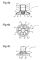
- Fig. 4a and 4b both show a cross-sectional view and a top view of an actuator element 3 shown in Fig. 1 .
- the actuator element comprises a volcano-shaped base.
- the base is formed primarily by the flexible membrane 10.
- a ridge 19 is provided on an outer side of the actuator element.
- the ridge 19 can be used to place the actuator element on a rim 25 of the top cover section 2.
- the ridge 19 can be arranged in order to pre-tension the actuator element, such that the actuator element 3 pretensions the valve to a closed position.
- a spring means 18 is provided which is formed by an upwardly directed ridge. This spring means 18 may also be arranged to pre-tension the valve in a closed position.
- the membrane passes into the upwardly extending tube element 14, wherein the tube element 14 is provided with sealing surfaces 15, 16.
- the membrane passes downwardly into the connecting means 6, 6' and then runs out into the valve 4.
- the connecting means 6, 6' are arranged in such a manner that a direct connection is formed between the container and the outflow orifice when the valve 4 moves downwards.
- the actuator element 3, the connecting means 6, 6' and the valve 4 are formed from a single integrated component, or, for example, from a resilient synthetic material. Because the component is made from a relatively resilient material, it is easy to place the component on the top cover section 2 in order to push the valve 4 through the through-flow orifice to position the valve upstream of the through-flow orifice. In addition, the flexible material is resilient enough to return the component to an undeformed state. This increases the reliability and the effective operation the flow control device 1.
- a protuberance is a prism tapering into a point. The point is connected on an outer side to the membrane 10. The base of the prism is connected to the tube element 14. One side of the prism matches the membrane 10.
- a flow control device (1) for a fluid container (20) is provided.
- the flow control device (1) is attachable to an orifice (22) of the fluid container, wherein the flow control device comprises a top cover section (2) with an outflow orifice (7), wherein a direct connection is formable between the container and the outflow orifice, wherein the outflow orifice is provided with a tube element (13), which extends in an upstream direction to an inner side of the top cover section, wherein upstream of the tube element a valve retaining element (5) with a through-flow orifice (8) is provided, the retaining element (5) being mountable on the orifice of the fluid container, wherein the flow control device is provided with a movable valve (4) upstream of the through-flow orifice for the alternate opening and closing of the through-flow orifice, wherein the flow control device is provided with a pre-tensioning means (3) for keeping the valve in a closed position, wherein the flow control device comprises an actuator element (3) which is arranged to bring the
- the actuator element (3) can also be the pre-tensioning means (3).
- said pre-tensioning means comprises a ridge (18) near to an outermost edge of the membrane (10), wherein a top of the ridge extends in the direction of the first chamber (11).
- said pre-tensioning means is provided with two or more protuberances (61, 61', 62I, 62II, 62III, 62IV, 62V, 62VI) which extend radially from the membrane.
- said protuberances (61, 61', 621, 62I, 62II, 62III, 62IV, 62V, 62VI) are arranged rotationally and symmetrically at a regular angular distance from one another.
- said actuator element can be provided near to an outermost edge with hook means (19), which are arranged to act cooperatively with a rim (25) formed on the flow control device for the detachable attachment of said actuator element to the flow control device.
Landscapes
- Engineering & Computer Science (AREA)
- Mechanical Engineering (AREA)
- Fluid-Driven Valves (AREA)
Abstract
Claims (14)
- Dispositif de commande d'écoulement (1) pour un récipient de fluide (20), dans lequel le dispositif de commande d'écoulement (1) peut être fixé sur un orifice (22) du récipient de fluide, dans lequel le dispositif de commande d'écoulement comprend une section de couvercle supérieur (2) avec un orifice de sortie (7), dans lequel un raccordement direct peut être formé entre le récipient et l'orifice de sortie, dans lequel l'orifice de sortie est prévu avec un élément de tube d'orifice de sortie (13), dans lequel en amont de l'élément de tube, on prévoit un élément de retenue de soupape (5) avec un orifice d'écoulement (8), l'élément de retenue (5) pouvant être monté sur l'orifice du récipient de fluide, dans lequel le dispositif de commande d'écoulement est prévu avec une soupape mobile (4) en amont de l'orifice d'écoulement pour l'ouverture et la fermeture alternées de l'orifice d'écoulement, dans lequel le dispositif de commande d'écoulement est prévu avec des moyens de pré-tension (3) pour maintenir la soupape dans une position fermée, dans lequel le dispositif de commande d'écoulement comprend un élément d'actionneur (3) qui est agencé pour amener la soupape dans une position ouverte, dans lequel l'élément d'actionneur est prévu avec une membrane souple (10) et un élément de tube d'actionneur (14) s'étendant dans une direction en aval, l'élément de tube d'actionneur (14) ayant une surface d'étanchéité (15, 16), dans lequel ladite surface d'étanchéité peut coulisser sur une coque de l'élément de tube d'orifice de sortie (13) pour raccorder de manière coulissante ledit élément d'actionneur, dans lequel une première chambre (11) est formée entre la section de couvercle supérieur et l'élément d'actionneur, la première chambre formant un raccordement ouvert avec l'air extérieur via des ouvertures (17) formées dans la section de couvercle supérieur, de sorte qu'une pression atmosphérique est dominante dans la première chambre, et dans lequel une deuxième chambre (12) est formée entre ledit élément d'actionneur, ledit élément de retenue de soupape et ledit orifice de sortie, dans lequel ledit élément d'actionneur est mobile dans une direction en amont grâce à une sous-pression dans la deuxième chambre par rapport à la première chambre afin d'amener la soupape dans une position ouverte, caractérisé en ce que l'élément de tube d'actionneur (14) a au moins deux surfaces d'étanchéité (15, 16) qui peuvent coulisser sur la coque de l'élément de tube d'orifice de sortie (13) pour raccorder de manière coulissante ledit élément d'actionneur, et dans lequel l'élément de tube d'orifice de sortie (13) s'étend dans une direction en amont jusqu'à un côté interne de la section de couvercle supérieur et dans lequel les au moins deux surfaces d'étanchéité (15, 16) peuvent coulisser sur une coque externe de l'élément de tube d'orifice de sortie (13).
- Dispositif de commande d'écoulement selon la revendication 1, dans lequel les au moins deux surfaces d'étanchéité (15, 16) sont agencées à une distance axiale l'une de l'autre.
- Dispositif de commande d'écoulement selon la revendication 1 ou 2, dans lequel les au moins deux surfaces d'étanchéité (15, 16) sont agencées sur une coque interne de l'élément de tube d'actionneur (14).
- Dispositif de commande d'écoulement selon l'une quelconque des revendications précédentes, dans lequel l'élément d'actionneur (3) est également le moyen de pré-tension (3).
- Dispositif de commande d'écoulement selon l'une quelconque des revendications précédentes, dans lequel ladite surface d'étanchéité comprend une protubérance (15, 16) formée sur une coque interne de l'élément de tube d'actionneur (14) qui s'étend de manière concentrique à partir de l'élément de tube d'actionneur (14).
- Dispositif de commande d'écoulement selon l'une quelconque des revendications précédentes, dans lequel l'élément d'actionneur (3) est raccordé de manière solidaire à la soupape (4), et/ou dans lequel ledit élément d'actionneur et ladite soupape sont composés d'un seul composant intégré.
- Elément d'actionneur pour un dispositif de commande d'écoulement selon les revendications 1 à 6, dans lequel ledit élément d'actionneur comprend une membrane (10) et un élément de tube d'actionneur (14) s'étendant vers le haut, dans lequel ledit élément de tube d'actionneur (14) est prévu avec au moins deux surfaces d'étanchéité (15, 16).
- Elément d'actionneur selon la revendication 7, dans lequel les au moins deux surfaces d'étanchéité (15, 16) sont agencées à une distance axiale l'une de l'autre.
- Elément d'actionneur selon la revendication 7 ou la revendication 8, dans lequel les au moins deux surfaces d'étanchéité (15, 16) sont prévues sur une coque interne de l'élément de tube d'actionneur (14).
- Elément d'actionneur selon l'une quelconque des revendications 7 à 9, dans lequel ladite surface d'étanchéité comprend une protubérance (15, 16) formée sur une coque interne de l'élément de tube d'actionneur (14).
- Elément d'actionneur selon la revendication 10, dans lequel la protubérance s'étend de manière concentrique à partir de l'élément de tube d'actionneur (14).
- Elément d'actionneur selon l'une quelconque des revendications 7 à 11, dans lequel l'élément d'actionneur comprend une soupape (4).
- Elément d'actionneur selon la revendication 12, dans lequel l'élément d'actionneur est prévu avec des moyens de raccordement (6, 6') qui raccordent ledit élément d'actionneur (3) avec ladite soupape (4).
- Elément d'actionneur selon la revendication 13, dans lequel ladite membrane (10), ledit élément de tube, lesdits moyens de raccordement (6, 6') et ladite soupape (4) sont raccordés de manière solidaire entre eux, et/ou sont composés d'un seul composant intégré.
Applications Claiming Priority (2)
| Application Number | Priority Date | Filing Date | Title |
|---|---|---|---|
| NL2001524A NL2001524C2 (nl) | 2008-04-25 | 2008-04-25 | Afsluitinrichting voor een houder voor vloeistoffen, en een actuatorelement daarvoor. |
| PCT/NL2009/050226 WO2009131457A1 (fr) | 2008-04-25 | 2009-04-24 | Dispositif de commande d'écoulement pour un récipient pour fluides, et élément d'actionneur |
Publications (2)
| Publication Number | Publication Date |
|---|---|
| EP2271560A1 EP2271560A1 (fr) | 2011-01-12 |
| EP2271560B1 true EP2271560B1 (fr) | 2012-06-20 |
Family
ID=40810422
Family Applications (1)
| Application Number | Title | Priority Date | Filing Date |
|---|---|---|---|
| EP09734205A Not-in-force EP2271560B1 (fr) | 2008-04-25 | 2009-04-24 | Dispositif de commande d'écoulement pour un récipient pour fluides, et élément d'actionneur |
Country Status (4)
| Country | Link |
|---|---|
| US (1) | US20110210149A1 (fr) |
| EP (1) | EP2271560B1 (fr) |
| NL (1) | NL2001524C2 (fr) |
| WO (1) | WO2009131457A1 (fr) |
Families Citing this family (7)
| Publication number | Priority date | Publication date | Assignee | Title |
|---|---|---|---|---|
| US8646634B2 (en) | 2011-06-23 | 2014-02-11 | Jan Essebaggers | Screw cap and a sport closure cap with integral inner seal opening means |
| NO20120456A1 (no) * | 2012-03-02 | 2013-09-03 | Smartseal As | Stengeanordning for en beholder |
| US9060592B2 (en) * | 2012-11-28 | 2015-06-23 | Specialized Bicycle Components, Inc. | Water bottle with poppet valve |
| CN104843304B (zh) * | 2015-04-01 | 2016-10-05 | 李红彪 | 可自动关闭的托盘式不漏嘴盖 |
| CN106923611B (zh) * | 2017-04-19 | 2018-04-20 | 杭州博达设计咨询有限公司 | 基于形变的360度饮水水杯 |
| JP7080471B2 (ja) * | 2018-02-22 | 2022-06-06 | 東京ライト工業株式会社 | キャップ及び吐出容器 |
| US12207722B2 (en) * | 2023-01-18 | 2025-01-28 | Mitsubishi Pencil Company, Limited | Applicator |
Family Cites Families (11)
| Publication number | Priority date | Publication date | Assignee | Title |
|---|---|---|---|---|
| US4583650A (en) * | 1983-08-17 | 1986-04-22 | Proprietary Technology | Manually releasable drainport closure apparatus |
| US5240154A (en) * | 1991-06-14 | 1993-08-31 | Al Van Den Berghe | Closure system for a container employing a bellows member |
| MXPA02011943A (es) * | 2000-06-01 | 2004-09-06 | Jan Essebaggers | Elemento de flujo con boquilla de succion para recipiente de bebidas carbonatadas que no permite el derrame. |
| US6290090B1 (en) * | 2000-06-01 | 2001-09-18 | Enpros Holding B.V. | Drip-less carbonated beverage container “flow control element” with suction spout |
| US6550493B2 (en) * | 2001-06-13 | 2003-04-22 | Baxter International Inc. | Vacuum demand valve |
| US6554023B2 (en) * | 2001-06-13 | 2003-04-29 | Baxter International Inc. | Vacuum demand flow valve |
| US7350666B2 (en) * | 2002-07-22 | 2008-04-01 | Jan Essebaggers | Self regulating spout |
| US20050087571A1 (en) * | 2002-09-20 | 2005-04-28 | Dark Richard C. | Fluid dispensing valve and method of assembly |
| NO323158B1 (no) * | 2003-09-16 | 2007-01-08 | Smartseal As | Anordning ved en ventil for en drikkebeholder |
| US7070065B2 (en) * | 2004-03-10 | 2006-07-04 | Fu Hong Industries Limited | Closure assembly for drinking vessel |
| US20130026196A1 (en) * | 2011-07-25 | 2013-01-31 | Jan Essebaggers | Self closing flow control device with adjustable actuator element for container closures |
-
2008
- 2008-04-25 NL NL2001524A patent/NL2001524C2/nl not_active IP Right Cessation
-
2009
- 2009-04-24 EP EP09734205A patent/EP2271560B1/fr not_active Not-in-force
- 2009-04-24 WO PCT/NL2009/050226 patent/WO2009131457A1/fr not_active Ceased
- 2009-04-24 US US12/989,624 patent/US20110210149A1/en not_active Abandoned
Also Published As
| Publication number | Publication date |
|---|---|
| US20110210149A1 (en) | 2011-09-01 |
| NL2001524C2 (nl) | 2009-11-04 |
| WO2009131457A1 (fr) | 2009-10-29 |
| EP2271560A1 (fr) | 2011-01-12 |
Similar Documents
| Publication | Publication Date | Title |
|---|---|---|
| EP2271560B1 (fr) | Dispositif de commande d'écoulement pour un récipient pour fluides, et élément d'actionneur | |
| AU2002322675B2 (en) | Fluid dispensing valve and method of use | |
| CN101959768B (zh) | 容器和封闭物的组件及封闭物 | |
| US8430261B2 (en) | Closure cover for tanks under internal pressure, with a safety function, and closure cover for a fuel tank | |
| US7624755B2 (en) | Gas valve with overtravel | |
| CN102803800B (zh) | 用于流体压力装置的阀结构 | |
| EP2833761B1 (fr) | Dispositif de couverture pour récipient de boisson | |
| AU2002322675A1 (en) | Fluid dispensing valve and method of use | |
| US11439260B2 (en) | Non-spill cup and fluid control valve system with all round drinking rim | |
| EP3154869B1 (fr) | Dispositif de couverture pour récipient de boisson | |
| TW200300816A (en) | Fuel vapor vent valve with peel-off mechanism for ensuring reopening | |
| CN102307791A (zh) | 用于容器的封闭装置 | |
| US10723528B2 (en) | Dispensing closures and dispensers | |
| CN113165859A (zh) | 用于通过包括分配阀的分配管来分配饮料的套件 | |
| RU2008148011A (ru) | Самозапирающийся клапан с клапанной крышкой | |
| US20050087571A1 (en) | Fluid dispensing valve and method of assembly | |
| US8584909B2 (en) | Dispensing tap for beverages | |
| CN101384489A (zh) | 用以受控地排放日用流体的具有可移动式阀件的容器 | |
| CN115003944A (zh) | 阀 | |
| EP3154401B1 (fr) | Dispositif d'operculage pour un contenant de boisson | |
| JP5820690B2 (ja) | 吐出ポンプ | |
| EP1460344B1 (fr) | Vase d'expansion avec clapet | |
| JP6903340B2 (ja) | 飲料容器およびキャップ組立体 | |
| NO132824B (fr) | ||
| JP6957030B2 (ja) | 飲料容器およびキャップ組立体 |
Legal Events
| Date | Code | Title | Description |
|---|---|---|---|
| PUAI | Public reference made under article 153(3) epc to a published international application that has entered the european phase |
Free format text: ORIGINAL CODE: 0009012 |
|
| 17P | Request for examination filed |
Effective date: 20101028 |
|
| AK | Designated contracting states |
Kind code of ref document: A1 Designated state(s): AT BE BG CH CY CZ DE DK EE ES FI FR GB GR HR HU IE IS IT LI LT LU LV MC MK MT NL NO PL PT RO SE SI SK TR |
|
| AX | Request for extension of the european patent |
Extension state: AL BA RS |
|
| 17Q | First examination report despatched |
Effective date: 20110426 |
|
| DAX | Request for extension of the european patent (deleted) | ||
| GRAP | Despatch of communication of intention to grant a patent |
Free format text: ORIGINAL CODE: EPIDOSNIGR1 |
|
| GRAS | Grant fee paid |
Free format text: ORIGINAL CODE: EPIDOSNIGR3 |
|
| GRAA | (expected) grant |
Free format text: ORIGINAL CODE: 0009210 |
|
| AK | Designated contracting states |
Kind code of ref document: B1 Designated state(s): AT BE BG CH CY CZ DE DK EE ES FI FR GB GR HR HU IE IS IT LI LT LU LV MC MK MT NL NO PL PT RO SE SI SK TR |
|
| REG | Reference to a national code |
Ref country code: GB Ref legal event code: FG4D |
|
| REG | Reference to a national code |
Ref country code: DE Ref legal event code: R082 Ref document number: 602009007748 Country of ref document: DE Representative=s name: ARNOLD & SIEDSMA, DE |
|
| REG | Reference to a national code |
Ref country code: CH Ref legal event code: EP |
|
| REG | Reference to a national code |
Ref country code: AT Ref legal event code: REF Ref document number: 562947 Country of ref document: AT Kind code of ref document: T Effective date: 20120715 |
|
| REG | Reference to a national code |
Ref country code: IE Ref legal event code: FG4D |
|
| REG | Reference to a national code |
Ref country code: NL Ref legal event code: T3 |
|
| REG | Reference to a national code |
Ref country code: DE Ref legal event code: R096 Ref document number: 602009007748 Country of ref document: DE Effective date: 20120816 |
|
| PG25 | Lapsed in a contracting state [announced via postgrant information from national office to epo] |
Ref country code: SE Free format text: LAPSE BECAUSE OF FAILURE TO SUBMIT A TRANSLATION OF THE DESCRIPTION OR TO PAY THE FEE WITHIN THE PRESCRIBED TIME-LIMIT Effective date: 20120620 Ref country code: NO Free format text: LAPSE BECAUSE OF FAILURE TO SUBMIT A TRANSLATION OF THE DESCRIPTION OR TO PAY THE FEE WITHIN THE PRESCRIBED TIME-LIMIT Effective date: 20120920 Ref country code: LT Free format text: LAPSE BECAUSE OF FAILURE TO SUBMIT A TRANSLATION OF THE DESCRIPTION OR TO PAY THE FEE WITHIN THE PRESCRIBED TIME-LIMIT Effective date: 20120620 Ref country code: FI Free format text: LAPSE BECAUSE OF FAILURE TO SUBMIT A TRANSLATION OF THE DESCRIPTION OR TO PAY THE FEE WITHIN THE PRESCRIBED TIME-LIMIT Effective date: 20120620 |
|
| REG | Reference to a national code |
Ref country code: AT Ref legal event code: MK05 Ref document number: 562947 Country of ref document: AT Kind code of ref document: T Effective date: 20120620 |
|
| REG | Reference to a national code |
Ref country code: LT Ref legal event code: MG4D Effective date: 20120620 |
|
| PG25 | Lapsed in a contracting state [announced via postgrant information from national office to epo] |
Ref country code: SI Free format text: LAPSE BECAUSE OF FAILURE TO SUBMIT A TRANSLATION OF THE DESCRIPTION OR TO PAY THE FEE WITHIN THE PRESCRIBED TIME-LIMIT Effective date: 20120620 Ref country code: LV Free format text: LAPSE BECAUSE OF FAILURE TO SUBMIT A TRANSLATION OF THE DESCRIPTION OR TO PAY THE FEE WITHIN THE PRESCRIBED TIME-LIMIT Effective date: 20120620 Ref country code: GR Free format text: LAPSE BECAUSE OF FAILURE TO SUBMIT A TRANSLATION OF THE DESCRIPTION OR TO PAY THE FEE WITHIN THE PRESCRIBED TIME-LIMIT Effective date: 20120921 Ref country code: HR Free format text: LAPSE BECAUSE OF FAILURE TO SUBMIT A TRANSLATION OF THE DESCRIPTION OR TO PAY THE FEE WITHIN THE PRESCRIBED TIME-LIMIT Effective date: 20120620 |
|
| PG25 | Lapsed in a contracting state [announced via postgrant information from national office to epo] |
Ref country code: AT Free format text: LAPSE BECAUSE OF FAILURE TO SUBMIT A TRANSLATION OF THE DESCRIPTION OR TO PAY THE FEE WITHIN THE PRESCRIBED TIME-LIMIT Effective date: 20120620 Ref country code: RO Free format text: LAPSE BECAUSE OF FAILURE TO SUBMIT A TRANSLATION OF THE DESCRIPTION OR TO PAY THE FEE WITHIN THE PRESCRIBED TIME-LIMIT Effective date: 20120620 Ref country code: BE Free format text: LAPSE BECAUSE OF FAILURE TO SUBMIT A TRANSLATION OF THE DESCRIPTION OR TO PAY THE FEE WITHIN THE PRESCRIBED TIME-LIMIT Effective date: 20120620 Ref country code: SK Free format text: LAPSE BECAUSE OF FAILURE TO SUBMIT A TRANSLATION OF THE DESCRIPTION OR TO PAY THE FEE WITHIN THE PRESCRIBED TIME-LIMIT Effective date: 20120620 Ref country code: CY Free format text: LAPSE BECAUSE OF FAILURE TO SUBMIT A TRANSLATION OF THE DESCRIPTION OR TO PAY THE FEE WITHIN THE PRESCRIBED TIME-LIMIT Effective date: 20120620 Ref country code: IS Free format text: LAPSE BECAUSE OF FAILURE TO SUBMIT A TRANSLATION OF THE DESCRIPTION OR TO PAY THE FEE WITHIN THE PRESCRIBED TIME-LIMIT Effective date: 20121020 Ref country code: CZ Free format text: LAPSE BECAUSE OF FAILURE TO SUBMIT A TRANSLATION OF THE DESCRIPTION OR TO PAY THE FEE WITHIN THE PRESCRIBED TIME-LIMIT Effective date: 20120620 Ref country code: EE Free format text: LAPSE BECAUSE OF FAILURE TO SUBMIT A TRANSLATION OF THE DESCRIPTION OR TO PAY THE FEE WITHIN THE PRESCRIBED TIME-LIMIT Effective date: 20120620 |
|
| PG25 | Lapsed in a contracting state [announced via postgrant information from national office to epo] |
Ref country code: IT Free format text: LAPSE BECAUSE OF FAILURE TO SUBMIT A TRANSLATION OF THE DESCRIPTION OR TO PAY THE FEE WITHIN THE PRESCRIBED TIME-LIMIT Effective date: 20120620 Ref country code: PL Free format text: LAPSE BECAUSE OF FAILURE TO SUBMIT A TRANSLATION OF THE DESCRIPTION OR TO PAY THE FEE WITHIN THE PRESCRIBED TIME-LIMIT Effective date: 20120620 Ref country code: PT Free format text: LAPSE BECAUSE OF FAILURE TO SUBMIT A TRANSLATION OF THE DESCRIPTION OR TO PAY THE FEE WITHIN THE PRESCRIBED TIME-LIMIT Effective date: 20121022 |
|
| PLBE | No opposition filed within time limit |
Free format text: ORIGINAL CODE: 0009261 |
|
| STAA | Information on the status of an ep patent application or granted ep patent |
Free format text: STATUS: NO OPPOSITION FILED WITHIN TIME LIMIT |
|
| PG25 | Lapsed in a contracting state [announced via postgrant information from national office to epo] |
Ref country code: ES Free format text: LAPSE BECAUSE OF FAILURE TO SUBMIT A TRANSLATION OF THE DESCRIPTION OR TO PAY THE FEE WITHIN THE PRESCRIBED TIME-LIMIT Effective date: 20121001 Ref country code: DK Free format text: LAPSE BECAUSE OF FAILURE TO SUBMIT A TRANSLATION OF THE DESCRIPTION OR TO PAY THE FEE WITHIN THE PRESCRIBED TIME-LIMIT Effective date: 20120620 |
|
| 26N | No opposition filed |
Effective date: 20130321 |
|
| REG | Reference to a national code |
Ref country code: DE Ref legal event code: R097 Ref document number: 602009007748 Country of ref document: DE Effective date: 20130321 |
|
| PG25 | Lapsed in a contracting state [announced via postgrant information from national office to epo] |
Ref country code: BG Free format text: LAPSE BECAUSE OF FAILURE TO SUBMIT A TRANSLATION OF THE DESCRIPTION OR TO PAY THE FEE WITHIN THE PRESCRIBED TIME-LIMIT Effective date: 20120920 |
|
| PG25 | Lapsed in a contracting state [announced via postgrant information from national office to epo] |
Ref country code: MC Free format text: LAPSE BECAUSE OF FAILURE TO SUBMIT A TRANSLATION OF THE DESCRIPTION OR TO PAY THE FEE WITHIN THE PRESCRIBED TIME-LIMIT Effective date: 20120620 |
|
| REG | Reference to a national code |
Ref country code: IE Ref legal event code: MM4A |
|
| PG25 | Lapsed in a contracting state [announced via postgrant information from national office to epo] |
Ref country code: IE Free format text: LAPSE BECAUSE OF NON-PAYMENT OF DUE FEES Effective date: 20130424 |
|
| PGFP | Annual fee paid to national office [announced via postgrant information from national office to epo] |
Ref country code: GB Payment date: 20140409 Year of fee payment: 6 |
|
| PGFP | Annual fee paid to national office [announced via postgrant information from national office to epo] |
Ref country code: CH Payment date: 20140409 Year of fee payment: 6 Ref country code: DE Payment date: 20140407 Year of fee payment: 6 Ref country code: NL Payment date: 20140407 Year of fee payment: 6 |
|
| PGFP | Annual fee paid to national office [announced via postgrant information from national office to epo] |
Ref country code: FR Payment date: 20140407 Year of fee payment: 6 |
|
| PG25 | Lapsed in a contracting state [announced via postgrant information from national office to epo] |
Ref country code: MT Free format text: LAPSE BECAUSE OF FAILURE TO SUBMIT A TRANSLATION OF THE DESCRIPTION OR TO PAY THE FEE WITHIN THE PRESCRIBED TIME-LIMIT Effective date: 20120620 |
|
| PG25 | Lapsed in a contracting state [announced via postgrant information from national office to epo] |
Ref country code: TR Free format text: LAPSE BECAUSE OF FAILURE TO SUBMIT A TRANSLATION OF THE DESCRIPTION OR TO PAY THE FEE WITHIN THE PRESCRIBED TIME-LIMIT Effective date: 20120620 |
|
| PG25 | Lapsed in a contracting state [announced via postgrant information from national office to epo] |
Ref country code: LU Free format text: LAPSE BECAUSE OF NON-PAYMENT OF DUE FEES Effective date: 20130424 Ref country code: HU Free format text: LAPSE BECAUSE OF FAILURE TO SUBMIT A TRANSLATION OF THE DESCRIPTION OR TO PAY THE FEE WITHIN THE PRESCRIBED TIME-LIMIT; INVALID AB INITIO Effective date: 20090424 Ref country code: MK Free format text: LAPSE BECAUSE OF FAILURE TO SUBMIT A TRANSLATION OF THE DESCRIPTION OR TO PAY THE FEE WITHIN THE PRESCRIBED TIME-LIMIT Effective date: 20120620 |
|
| REG | Reference to a national code |
Ref country code: DE Ref legal event code: R119 Ref document number: 602009007748 Country of ref document: DE |
|
| REG | Reference to a national code |
Ref country code: CH Ref legal event code: PL |
|
| GBPC | Gb: european patent ceased through non-payment of renewal fee |
Effective date: 20150424 |
|
| REG | Reference to a national code |
Ref country code: NL Ref legal event code: MM Effective date: 20150501 |
|
| PG25 | Lapsed in a contracting state [announced via postgrant information from national office to epo] |
Ref country code: DE Free format text: LAPSE BECAUSE OF NON-PAYMENT OF DUE FEES Effective date: 20151103 Ref country code: CH Free format text: LAPSE BECAUSE OF NON-PAYMENT OF DUE FEES Effective date: 20150430 Ref country code: LI Free format text: LAPSE BECAUSE OF NON-PAYMENT OF DUE FEES Effective date: 20150430 Ref country code: GB Free format text: LAPSE BECAUSE OF NON-PAYMENT OF DUE FEES Effective date: 20150424 |
|
| REG | Reference to a national code |
Ref country code: FR Ref legal event code: ST Effective date: 20151231 |
|
| PG25 | Lapsed in a contracting state [announced via postgrant information from national office to epo] |
Ref country code: FR Free format text: LAPSE BECAUSE OF NON-PAYMENT OF DUE FEES Effective date: 20150430 |
|
| PG25 | Lapsed in a contracting state [announced via postgrant information from national office to epo] |
Ref country code: NL Free format text: LAPSE BECAUSE OF NON-PAYMENT OF DUE FEES Effective date: 20150501 |