EP2271840B1 - Ventilateur de transfert de chaleur autonome - Google Patents
Ventilateur de transfert de chaleur autonome Download PDFInfo
- Publication number
- EP2271840B1 EP2271840B1 EP08748272.5A EP08748272A EP2271840B1 EP 2271840 B1 EP2271840 B1 EP 2271840B1 EP 08748272 A EP08748272 A EP 08748272A EP 2271840 B1 EP2271840 B1 EP 2271840B1
- Authority
- EP
- European Patent Office
- Prior art keywords
- heat transfer
- fan
- module
- motor
- heat
- Prior art date
- Legal status (The legal status is an assumption and is not a legal conclusion. Google has not performed a legal analysis and makes no representation as to the accuracy of the status listed.)
- Active
Links
Images





Classifications
-
- F—MECHANICAL ENGINEERING; LIGHTING; HEATING; WEAPONS; BLASTING
- F04—POSITIVE - DISPLACEMENT MACHINES FOR LIQUIDS; PUMPS FOR LIQUIDS OR ELASTIC FLUIDS
- F04D—NON-POSITIVE-DISPLACEMENT PUMPS
- F04D25/00—Pumping installations or systems
- F04D25/02—Units comprising pumps and their driving means
- F04D25/04—Units comprising pumps and their driving means the pump being fluid-driven
-
- F—MECHANICAL ENGINEERING; LIGHTING; HEATING; WEAPONS; BLASTING
- F04—POSITIVE - DISPLACEMENT MACHINES FOR LIQUIDS; PUMPS FOR LIQUIDS OR ELASTIC FLUIDS
- F04D—NON-POSITIVE-DISPLACEMENT PUMPS
- F04D25/00—Pumping installations or systems
- F04D25/02—Units comprising pumps and their driving means
- F04D25/06—Units comprising pumps and their driving means the pump being electrically driven
- F04D25/0606—Units comprising pumps and their driving means the pump being electrically driven the electric motor being specially adapted for integration in the pump
-
- F—MECHANICAL ENGINEERING; LIGHTING; HEATING; WEAPONS; BLASTING
- F04—POSITIVE - DISPLACEMENT MACHINES FOR LIQUIDS; PUMPS FOR LIQUIDS OR ELASTIC FLUIDS
- F04D—NON-POSITIVE-DISPLACEMENT PUMPS
- F04D25/00—Pumping installations or systems
- F04D25/02—Units comprising pumps and their driving means
- F04D25/08—Units comprising pumps and their driving means the working fluid being air, e.g. for ventilation
-
- F—MECHANICAL ENGINEERING; LIGHTING; HEATING; WEAPONS; BLASTING
- F24—HEATING; RANGES; VENTILATING
- F24B—DOMESTIC STOVES OR RANGES FOR SOLID FUELS; IMPLEMENTS FOR USE IN CONNECTION WITH STOVES OR RANGES
- F24B7/00—Stoves, ranges or flue-gas ducts, with additional provisions for convection heating
-
- F—MECHANICAL ENGINEERING; LIGHTING; HEATING; WEAPONS; BLASTING
- F24—HEATING; RANGES; VENTILATING
- F24B—DOMESTIC STOVES OR RANGES FOR SOLID FUELS; IMPLEMENTS FOR USE IN CONNECTION WITH STOVES OR RANGES
- F24B7/00—Stoves, ranges or flue-gas ducts, with additional provisions for convection heating
- F24B7/02—Stoves, ranges or flue-gas ducts, with additional provisions for convection heating with external air ducts
- F24B7/025—Stoves, ranges or flue-gas ducts, with additional provisions for convection heating with external air ducts with forced circulation
-
- F—MECHANICAL ENGINEERING; LIGHTING; HEATING; WEAPONS; BLASTING
- F24—HEATING; RANGES; VENTILATING
- F24H—FLUID HEATERS, e.g. WATER OR AIR HEATERS, HAVING HEAT-GENERATING MEANS, e.g. HEAT PUMPS, IN GENERAL
- F24H3/00—Air heaters
- F24H3/02—Air heaters with forced circulation
- F24H3/04—Air heaters with forced circulation the air being in direct contact with the heating medium, e.g. electric heating element
-
- F—MECHANICAL ENGINEERING; LIGHTING; HEATING; WEAPONS; BLASTING
- F24—HEATING; RANGES; VENTILATING
- F24H—FLUID HEATERS, e.g. WATER OR AIR HEATERS, HAVING HEAT-GENERATING MEANS, e.g. HEAT PUMPS, IN GENERAL
- F24H3/00—Air heaters
- F24H3/02—Air heaters with forced circulation
- F24H3/04—Air heaters with forced circulation the air being in direct contact with the heating medium, e.g. electric heating element
- F24H3/0494—Air heaters with forced circulation the air being in direct contact with the heating medium, e.g. electric heating element using solid fuel
-
- F—MECHANICAL ENGINEERING; LIGHTING; HEATING; WEAPONS; BLASTING
- F24—HEATING; RANGES; VENTILATING
- F24D—DOMESTIC- OR SPACE-HEATING SYSTEMS, e.g. CENTRAL HEATING SYSTEMS; DOMESTIC HOT-WATER SUPPLY SYSTEMS; ELEMENTS OR COMPONENTS THEREFOR
- F24D2200/00—Heat sources or energy sources
- F24D2200/07—Solid fuel burners
Definitions
- This invention relates to heat transfer fans, particularly to such fans for use in conjunction with cooled or heated surfaces, and more particularly, with fossil-fuel burning stoves.
- Heating units such as wood and other fossil-fuel combustible material burning stoves, hot water radiators and the like disseminate heat into surrounding space by radiation and by convection of thermal air currents circulating around the unit.
- Warm air distribution from the unit may be enhanced by means of an air blower or fan suitably placed on or adjacent the unit.
- air blower or fan suitably placed on or adjacent the unit.
- air circulating fans are powered by electric battery or mains power supply.
- thermoelectric couple When a direct electric current is passed through a thermoelectric couple, heat will be absorbed at one end of the couple to cause cooling thereof, while heat is rejected at the other end of the couple to cause a rise in temperature. By reversing the current flow, the direction of heat flow will be reversed.
- thermoelectric modules are forms of a thermoelectric couple and, typically, comprise an array of semiconductor couples (P and N pellets) connected electrically in series and thermally in parallel, sandwiched between metallized ceramic substrates.
- thermoelectric module behaves like a simple thermocouple in generating an electric potential across its terminals if a temperature gradient or thermocline is provided across the module when in an open circuit mode.
- electric power is generated as a function of the temperature difference between both ends of the module.
- Pertinent prior art comprises a demonstration model of a power generation module powering an air circulation fan disclosed by Tellurex Corporation, Michigan, U.S.A.
- the Tellurex Corporation self-powered fan comprises a hot end heat exchanger heated by a handheld propane torch, electric motor, fan blades, a cold end heat exchanger and a thermoelectric module sandwiched in thermal contact between the two heat exchangers and in electric contact with the electric motor.
- the module is heated by a propane torch to merely demonstrate current generation while requiring a hand held pyrometer to prevent overheating and destruction of the module.
- thermoelectric module could not be satisfactorily and reliably used to circulate heat from a hot surface, since sufficiently high temperatures of the hot surface sufficient to provide an effective air circulation effect would cause the thermoelectric module to simply overheat and be destroyed. Further, the orientation of the fan and the cool end heat sink are so located relative to the heat source as to cause passage of the hot gases on the hot side of the thermoelectric module around and through the cool end heat sink. Thus, the Tellurex Corporation demonstration model has no practical and reliable utility as a warm air circulating fan if placed on a heated surface.
- EP patent publication numbers 1669672 , 1669671 and Japanese patent number JP S56121941 also describe devices that power fans using the SeeBeck Thermocouple Effect.
- thermocouple module not only is warm air propelled forward from the unit to provide warm air circulation but that incoming cooler air pulled by the fan operates to enhance cooling of the heat sink cool end and, when appropriate, the hot end of the thermocouple module to provide reduced risk of damage through overheating of the thermocouple module.
- USP 5,544,488 teaches that an air circulation fan powered only by a thermoelectric module cooled at the cooling surface of a cooling system, such as, for example, provided by ice/water or a refrigeration system can provide useful air circulation, notwithstanding the extremely low efficiency of conversion of thermal energy to electrical energy inherent in the Seebeck Thermocouple Effect. Judicious selection of components and the physical arrangement of these components to constitute an air circulation fan suitable efficacious air circulation is reliably and safely obtained.
- the invention provides a self-powered fan for circulating air in combination with a heat source, said fan comprising a first heat transfer member having a first heat transfer surface thermally and physically connected with said heat source, electric motor, fan blades which operably create a first or warm air flow and a second or cooler air flow, a second heat transfer member having a second heat transfer surface, thermocouple structure located between said first heat transfer member and said second heat transfer member, wherein said thermocouple structure co-operable with said motor, said first heat transfer member and said second heat transfer member, wherein said first heat transfer member being of suitable material, size, mass and shape as to provide a suitable temperature gradient between said thermocouple structure and said heat source to operably allow of such sufficient heat transfer from said first heat transfer member to said thermocouple structure to generate sufficient power to effect rotation of said blades, but not to cause thermal damage to said thermocouple structure; and wherein said fan blades are constructed and arranged to cause a portion of said second air flow to be drawn past said first heat transfer surface to effect a cooling heat transfer
- the invention provides a self-powered fan for circulating air in combination with a heat source having a heated surface, said fan comprising:
- the heat transfer means comprises a base of the fan which rests upon the top of or is adjacent in contact with a heat source such as a fossil-fuel burning stove, for instance a coal fired or wood burning stove.
- the fan is a device to circulate warmed air from the hot stove surface.
- the fan uses the difference in temperature between the hot surface of the stove upon which the fan is resting and the surrounding air to power the fan.
- the power is derived by utilizing a thermoelectric module, preferably consisting of an array of thermocouples.
- the current generated is used to power a d.c. motor which operates the fan blades to circulate warm air and maintain the temperature difference across the thermocouple.
- the fan draws all of its power from the heated surface and requires no external electrical power source. Most importantly, the fan stops, starts and runs automatically and provides variable air circulation in proportion to the amount of heat provided to the hot side heat exchanger base and resultant thermocline across the thermocouple module.
- thermocouple module By suitable selection of material and the surface area, size, mass and shape of the hot end heat exchanger, suitable temperature gradients between the thermocouple module and the stove can be obtained to operably allow sufficient heat to reach the hot end of the module, without destroying it, and to generate sufficient power to effect rotation of the fan blades.
- suitable determination of material, surface area, size, mass and shape may be readily determined by the skilled person in the art.
- the hot end heat exchanger comprises a base, which operatively abuts the heat source, and a heat conductive member having a length connecting with the thermocouple for transferring heat thereto.
- the length of this member is so chosen as to be sufficient as to provide a suitable temperature gradient between the heat source and the thermocouple as to effect blade rotation without damage of the thermocouple by overheating.
- the fan blades are, preferably, so oriented relative to the hot end heat transfer base as to cause a portion of the ambient air flow to be drawn past the hot end heat transfer base in order to effect a cooling heat transfer effect upon the base.
- the greater the temperature gradient across the module caused by an increase in temperature of the heated base the greater the power generated with commensurate fan speed. Increased fan speed causes faster air flow around the fan and base to enhance cooling of the latter. Thus, this cooling effect constitutes a useful safety feature.
- the axis of rotation of the fan is angularly displaced, most preferably perpendicularly, to the hot and cold heat transfer means and module.
- the cool end heat exchanger comprises a plurality of cooling vanes dissipating heat from the module. It is highly desirable that the vanes are so disposed relative to the fan blades that the vanes extend through the cool air low stream generated by the rotation of the fan blades. In one embodiment according to the invention the cooling vanes are so disposed one vane to another as to take the form of a fan-shaped array.
- the fan blades are so shaped and located relative to the module and heat exchange means as to cause cooler air to pass adjacent to and/or through the heat sink cool end.
- the fan may have a protective wire frame or shroud to prevent physical injury, and which also is connected to the module to act as a cool end heat exchanger to dissipate heat from the module.
- the heat exchanger members of the fan may be formed of any suitable material, such as a metal or metal alloy, for example of aluminum, copper and iron.
- fans according to the invention can provide satisfactory air circulation when the fan module is operative at a temperature gradient of the order of as low as 30° C.
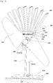
- fan 100 of the prior art exemplified by USP 5,544,488 comprises a TE module 112 (cpl. 0-127-08L Melcor Frigichips, U.S.A.) comprised of an array of semiconductor couples (P and N pellets) connected electrically in series and thermally in parallel sandwiched between metallized ceramic substrates 114 and 116 according to the prior art.
- This module 112 can withstand temperatures only up to about 80.degree. C.
- Module 112 has an electrical connection with motor 118, which, drives fan blades 120, shown in outline only for clarity.
- Fan 100 has a heat transfer member, shown generally as 122 having a rectangular-shaped base portion 124 having a lower surface 126 in operable contact with a heated surface of a stove or the like 125. Upstanding from rectangular base member 124 is an integrally formed vertically aligned planar heat transfer portion 128 upon which is an integrally formed heat transfer portion 130. Member 122 is, thus, constituted by integrally formed portions 124, 128 and 130 formed of aluminum. Portion 130 is in thermal communication with the lower ceramic member 114 of module 112.
- a cool end heat exchanger 132 formed of aluminum and consisting of a base 134, connected to module 112, and an array of vanes 136.
- Portion 128 is so shaped as to provide the necessary heat control of heat from portion 124 to module 112, irrespective of the temperature, within reasonable limits, of the stove 125 heat source, as hereinafter more fully explained. Stove temperatures of up to, for example, 500°C may be obtained in practice and acceptable to fans.
- the mass and shape of base 124 and the distance or length, mass and shape of 128 between base 124 and module 134 is such as to provide a suitable temperature gradient between base 124 and module 134 as to cause sufficient current generation for desired fan rotation without damage of module 134 by heat when the heated stove surface 125 is at a temperature of not greater than 500°C.
- FIGS. 3 and 4 show fan 100 on top of a stove 125.
- FIG. 3 depicts gentle air circulation created by stove 125 having a low fire and, thus, low heat transfer therefrom to module 112, via heat transfer member 122.
- low power generation occurs due to a relatively small thermocline.
- fan 100 produces a gentle air circulation that bends the superheated air from the convection stream and sends it forwards into the area in front of stove 125.
- the airflow is sufficient to bring cool room temperature air through the coolside heat exchanger to maintain a thermocline across module 112 and produce enough current to maintain an adequate air circulation.
- the superheated convection currents are allowed to pass the base, or hotside heat exchanger and maintain as large a thermocline as is necessary.
- FIG. 4 depicts air circulation created by stove 125 having a high fire.
- the increase in heat provided by the high fire provides more current for fan 100 and the resultant air passing through fan 100 increases greatly.
- the superheated air from convection is now being pushed rapidly across the stovetop and cool room temperature air flows through the coolside exchanger as in the earlier example, and is also drawn past the hotside exchanger.
- This latter process is absolutely critical to the operation of the unit as it strips heat from the hotside exchanger before it reaches module 112 and keeps module 112 well within operational tolerances with regard to temperature.
- the shape, mass, size and material composition of heat transfer member 122 is suitable selected, efficient cooling of member 122 by the rapid cool air flow will prevent excess heat transfer to and damage of module 112.
- motor 118 of fan 100 is located adjacent the cold side of heat exchanger 132 of module 112, above module 112, i.e. on the side remote from heat transfer portion 130 in the embodiment shown in Figs. 1 and 2 .
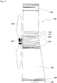
- Figs. 5 and 6 show, generally as 200, a preferred embodiment according to the invention, wherein the length of planar heat transfer stem portion 228 is integrally formed with an enlarged heat transfer portion 231 which is in thermal communication with the lower ceramic member 214 of module 212, itself in communication with upper ceramic member 216, and, thus, cool end heat exchanger 232 consisting of base 234 and an array of vanes 236.
- Lower base 224, stem 228, heat transfer portion 231, upper base 234, and vanes 236 are formed of aluminum.
- Enlarged heat transfer portion 231 has a housing portion which defines a cylindrical aperture 229, which receives and retains motor 218. This arrangement provides motor 218 to be mounted in the housing portion of the enlarged heat transfer portion 231 below lower module land 230 and, thus, below module 214.
- motor 218 is located on the side of module 214 remote from cool end heat exchanger 232.
- Cavity 229 in this embodiment is defined as a full depth cylindrical aperture, but may in less preferred embodiments be a suitably sized and shaped recess.
- Motor 218 is housed in housing portion 231 by any suitable means (not shown).
- cool heat exchanger 232 facilitates assembly and allows a greater range of shapes of the upper exchanger to be used, provided exchanger 232 has suitable surface areas for thermal conductivity and radiation.
- Fig 7 shows the front view of prior art fan 100 superimposed with a hatched area 301A that shows the most effective airflow area.
- Fig. 7a represents a side view of prior art fan 100 with arrows showing the airflow in cross section. The longer arrows show the most effective airflow area.
- Fig 8 shows improved design 302 according to the invention with the same hatched area 301B superimposed.
- Fig. 8a represents a side view of fan 200 with arrows showing the airflow in cross section. The longer arrows show the most effective airflow area.
- motor 118 blocks the most effective part of the old design upper exchanger 132 whereas the new location of motor 218 of the invention virtually unimpedes the upper air flows. Additionally, the lesser airflow in the fan 200 is drawn through and past aperture 229 of motor 218, which cools motor 218 and increases the cooling of lower exchanger 228.
- stem 228 is of a relatively longer length than heat exchanger stem portion 118 of prior art Fig. 1 embodiment, whilst other fan dimensions are substantially the same.
- the longer stem 228 creates a longer path for the heat to travel to the lower module land 230 and increases the surface area in consequence of which overheat bimetallic lifters or screws used in the embodiments of prior art of aforesaid USP 5,544,488 are no longer required.
- Such bimetallic lifters or screws are required to raise the fan base from the stove surface when the stove top exceeds the temperature range that will damage the module, if exceeded.
- With the preferred stem and motor arrangement of the present invention and base exchanger such overheat lifters are no longer required as enough heat is dissipated from the base and stem to protect the module through extreme heat.
- the motor is now shielded from the direct radiant heat from the stove top and runs much cooler and prevents the bearings lubrication from drying out as quickly.
- Motor 218, in preferred embodiments when located within aperture 229 is protected from overheating from the heat present in upper stem portion 231, by cool air flow through aperture 229 around motor 218.
- any upper heat exchanger 232 can be used without the need to redesign the lower unit 228, providing it has appropriate conductivity and sufficient swept surface area.
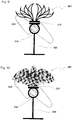
- unit 232 is not limited to extruded parts, but could also use cast pieces to add many more design categories. Shapes in the form of, for example, birds, flags, flowers and other sorts of known or abstract shapes is now possible to address different markets. Such embodiments are shown in Figs. 9 and 10 .
- Figure 11 represents comparative graphs of the base temperatures plotted against the temperatures of the lower module contact surface 130 according to the prior art (A) and 230 according to the invention (B). It can, surprisingly, be clearly seen that the module used in the invention fan runs much cooler. At a base temperature of 302°C the invention fan 200 showed 108°C while prior art fan 100 was at 142°C. At a base temperature of 148°C the module hot exchanger of the prior art fan reached 170°C. Fan 200 sinks much more heat from the stove surface so that the base could not be heated beyond 318°C, at which temperature the module side of the heat exchanger reached 112°C.
- Figure 12 represents comparative graphs of the base temperatures against the power output from the modules in watts. Both fans carried identical motors. Up to approximately 250°C, the output was virtually the same. However, from that point upwards, surprisingly, the curves diverge. At a base temperature of 318°C, the prior art fan 100 developed 1.145 watts, while fan 200 developed 1.385 watts, i.e. over 20% higher than the prior art fan 100. Again, while the test equipment consisted of a 10,000 BTU propane heater, the base temperature did not rise beyond 318°C in fan 200 as it was stripping the heat from the test surface. As an aside, it should be noted that the bi-metal overheat protection strip was not present in fan 100 or the comparative gains would have been much greater.
- the new fan 200 is, surprisingly, both more powerful and more durable than prior art fan 100.
Landscapes
- Engineering & Computer Science (AREA)
- Mechanical Engineering (AREA)
- General Engineering & Computer Science (AREA)
- Chemical & Material Sciences (AREA)
- Combustion & Propulsion (AREA)
- Physics & Mathematics (AREA)
- Thermal Sciences (AREA)
- Structures Of Non-Positive Displacement Pumps (AREA)
Claims (9)
- Ventilateur autonome (200) pour faire circuler l'air en combinaison avec une source de chaleur (225), ledit ventilateur comprenant :un premier élément de transfert de chaleur (228) ayant une première surface de transfert de chaleur (226) qui s'appuie sur, ou est adjacente à ladite source de chaleur (225),un moteur électrique (218), avec des pales de ventilateur (220) qui créent de manière opérationnelle un premier flux d'air, ou chaud, et un deuxième flux d'air, ou plus frais,un deuxième élément de transfert de chaleur (232) ayant une deuxième surface de transfert de chaleur (234),un module à thermocouple (212) localisé entre ledit premier élément de transfert de chaleur (228) et ledit deuxième élément de transfert de chaleur (232), ledit module à thermocouple (212) étant apte à fonctionner conjointement avec ledit moteur (218), ledit premier élément de transfert de chaleur (228) et ledit deuxième élément de transfert de chaleur (232), de sorte à générer et à fournir de l'énergie électrique audit moteur (218) en vertu d'un effet de thermocouple Seebeck,dans lequel ledit premier élément de transfert de chaleur (228) a une taille, une masse et une forme de sorte à fournir un gradient de température entre ledit module à thermocouple (212) et ladite source de chaleur (225) et à permettre par conséquent un transfert de chaleur à partir dudit premier élément de transfert de chaleur (228) vers ledit module à thermocouple (212) dans le but de générer de l'énergie électrique pour ledit moteur (218) pour qu'il soit apte à effectuer la rotation desdites pales de ventilateur (220), tout en évitant un endommagement thermique sur ledit module à thermocouple (212) ; etdans lequel lesdites pales de ventilateur (220) sont construites et agencées de façon à obliger une portion dudit deuxième flux d'air à être aspirée par devant ladite première surface de transfert de chaleur (226) afin d'effectuer un effet de transfert de chaleur refroidissant sur ledit premier élément de transfert de chaleur (228),caractérisé en ce que ledit moteur (218) est localisé sur ledit premier élément de transfert de chaleur (228) en position adjacente à un côté dudit module à thermocouple (212) et éloigné dudit deuxième élément de transfert, en vertu de quoi ledit moteur (218) n'entrave pas ledit deuxième flux d'air, et dans lequel ledit module à thermocouple (212) fournit davantage d'énergie délivrée audit moteur (218) pour procurer une vitesse de rotation améliorée dudit ventilateur (200) afin d'éviter que ledit moteur de ventilateur (218) ne soit endommagé thermiquement par ledit premier élément de transfert de chaleur (228) ou ladite source de chaleur (225).
- Ventilateur (200) tel que revendiqué dans la revendication 1, dans lequel ledit premier élément de transfert de chaleur (228) définit une cavité réceptrice de moteur (229) qui reçoit ledit moteur (218).
- Ventilateur (200) tel que revendiqué dans la revendication 2, dans lequel ladite cavité (229) est une ouverture.
- Ventilateur (200) tel que revendiqué dans la revendication 2, dans lequel ladite cavité (229) est un évidement.
- Ventilateur autonome (200) tel que revendiqué dans la revendication 1, dans lequel :ledit premier élément de transfert de chaleur (228) comprend une portion base (224) avec une surface (226) construite et agencée de façon à se mettre au contact de la surface chauffée de la source de chaleur (225), etune portion transfert de chaleur (228) qui s'étend à partir de ladite base (224), ladite portion transfert de chaleur (228) ayant des première et deuxième extrémités, ladite première extrémité étant couplée à ladite base (224),ledit module à thermocouple (212) comprend un module thermo-électrique ayant des première et deuxième surfaces d'extrémité, ladite première surface d'extrémité étant montée sur ladite deuxième extrémité de ladite portion transfert de chaleur (228) dudit premier élément de transfert de chaleur (228) de telle sorte que ladite portion transfert de chaleur (228) conduise la chaleur vers ledit module thermo-électrique,ledit deuxième élément de transfert de chaleur (232) comprend une structure d'échange de chaleur montée sur ladite deuxième surface d'extrémité dudit module thermo-électrique de sorte à contrôler une quantité de chaleur conduite à la partie supérieure dudit module thermo-électrique,un moteur électrique (218) couplé électriquement audit module thermo-électrique, et des pales de ventilateur (220) couplées audit moteur électrique (218),dans lequel ladite portion transfert de chaleur (228) dudit premier élément de transfert de chaleur (228) fournit un gradient de température entre ledit module thermo-électrique et ladite source de chaleur (225) et permet un transfert de chaleur à partir de ladite portion transfert de chaleur (228) vers ledit module thermo-électrique (212) dans le but de fournir de l'énergie audit moteur (218) pour effectuer la rotation desdites pales (220) sans causer un endommagement thermique sur ledit module thermo-électrique, lesdites pales de ventilateur (220) étant construites et agencées relativement à ladite portion base (224) et la portion transfert de chaleur (228) de façon à obliger une portion du flux d'air ambiant à être aspirée par devant ladite portion base (224) et la portion transfert de chaleur (228) effectuant un refroidissement de ladite portion base (224) ;dans lequel ledit moteur (218) est localisé au niveau de ladite deuxième extrémité de ladite portion transfert de chaleur (228) dudit premier élément de transfert de chaleur (228) adjacente à ladite première surface d'extrémité dudit module thermo-électrique (212).
- Ventilateur autonome (200) tel que revendiqué dans la revendication 5, dans lequel ladite portion transfert de chaleur (228) est construite et agencée de façon à limiter le transfert de chaleur à partir de ladite portion base (224) jusqu'audit module thermo-électrique (212) de telle sorte que, lorsque ladite surface chauffée se trouve à une température de 500° C ou moins, la température dudit module ne dépassera pas la température d'exploitation du module ou du moteur (218).
- Ventilateur (200) tel que revendiqué dans la revendication 5, dans lequel ladite portion transfert de chaleur (228) adjacente à ladite deuxième extrémité définit une cavité réceptrice de moteur (229) qui reçoit ledit moteur (218).
- Ventilateur (200) tel que revendiqué dans la revendication 7, dans lequel ladite cavité (229) est une ouverture.
- Ventilateur (200) tel que revendiqué dans la revendication 7, dans lequel ladite cavité (229) est un évidement.
Applications Claiming Priority (1)
| Application Number | Priority Date | Filing Date | Title |
|---|---|---|---|
| PCT/CA2008/000873 WO2009135285A1 (fr) | 2008-05-08 | 2008-05-08 | Ventilateur de transfert de chaleur autonome |
Publications (3)
| Publication Number | Publication Date |
|---|---|
| EP2271840A1 EP2271840A1 (fr) | 2011-01-12 |
| EP2271840A4 EP2271840A4 (fr) | 2015-04-01 |
| EP2271840B1 true EP2271840B1 (fr) | 2019-07-10 |
Family
ID=41264355
Family Applications (1)
| Application Number | Title | Priority Date | Filing Date |
|---|---|---|---|
| EP08748272.5A Active EP2271840B1 (fr) | 2008-05-08 | 2008-05-08 | Ventilateur de transfert de chaleur autonome |
Country Status (2)
| Country | Link |
|---|---|
| EP (1) | EP2271840B1 (fr) |
| WO (1) | WO2009135285A1 (fr) |
Families Citing this family (6)
| Publication number | Priority date | Publication date | Assignee | Title |
|---|---|---|---|---|
| GB2484954A (en) * | 2010-10-27 | 2012-05-02 | Ramiro Javier Villanueva | Combined fan, thermoelectric device and heat pipe used to circulate air that has been heated by a heating appliance |
| TR201107752A2 (tr) * | 2011-08-05 | 2012-07-23 | Co�Kun�Z Metal Form Mak�Na End�Str� Ve T�C. A.�. | Bir radyatör tertibatı. |
| LT5978B (lt) | 2012-03-16 | 2013-12-27 | Uab "Trijų Artelė" | Autonominis šilumos skirstytuvas su kojelėmis |
| CN105946076B (zh) * | 2016-05-10 | 2017-09-01 | 邱禹迪 | 木制支架微型电风扇的加工方法 |
| GB2551040B (en) * | 2017-05-10 | 2018-06-20 | Valiant Stoves Ltd | Flue-Pipe Fan |
| RU180646U1 (ru) * | 2017-10-20 | 2018-06-19 | Александр Евгеньевич Владимиров | Осевой вентилятор для бани и сауны |
Family Cites Families (9)
| Publication number | Priority date | Publication date | Assignee | Title |
|---|---|---|---|---|
| JPS56121941A (en) * | 1980-02-29 | 1981-09-25 | Tdk Corp | Device for generating hot air |
| JPS6298149A (ja) * | 1985-10-25 | 1987-05-07 | Saamobonitsuku:Kk | 温風発生装置 |
| CA2103734C (fr) * | 1993-08-10 | 2003-07-08 | Randall Hillis Reid | Ventilateur autodynamique pour le transfert de la chaleur |
| US6019098A (en) * | 1993-10-19 | 2000-02-01 | Hi-Z Technology, Inc. | Self powered furnace |
| JP2001221508A (ja) * | 2000-02-08 | 2001-08-17 | Matsushita Electric Ind Co Ltd | 温風送風機 |
| US6588419B1 (en) * | 2002-06-10 | 2003-07-08 | Honeywell International Inc. | Fireplace insert thermally generating electrical power useful for operating a circulating fan |
| FR2878942B1 (fr) * | 2004-12-07 | 2007-04-27 | Gaz De Petrole | Dispositif de chauffage a convection avec alimentation electrique autonome du ventilateur |
| FR2878941B1 (fr) * | 2004-12-07 | 2007-03-02 | Gaz De Petrole | Appareil de chauffage a convection avec alimentation electrique autonome du ventilateur |
| CA2570928C (fr) | 2006-12-12 | 2014-05-13 | Randall H. Reid | Ventilateur autonome de transfert thermique |
-
2008
- 2008-05-08 WO PCT/CA2008/000873 patent/WO2009135285A1/fr not_active Ceased
- 2008-05-08 EP EP08748272.5A patent/EP2271840B1/fr active Active
Non-Patent Citations (1)
| Title |
|---|
| None * |
Also Published As
| Publication number | Publication date |
|---|---|
| EP2271840A1 (fr) | 2011-01-12 |
| EP2271840A4 (fr) | 2015-04-01 |
| WO2009135285A1 (fr) | 2009-11-12 |
Similar Documents
| Publication | Publication Date | Title |
|---|---|---|
| US7812245B2 (en) | Self powered heat transfer fan | |
| US5544488A (en) | Self-powered heat transfer fan | |
| WO2009135285A1 (fr) | Ventilateur de transfert de chaleur autonome | |
| KR102228038B1 (ko) | 액체 열전달 매체를 이용한 냉난방 장치 | |
| CN102570289A (zh) | 一种光纤耦合模块的温控散热系统 | |
| US20210408353A1 (en) | Heat sink shield and thermoelectric fan with heat sink shield | |
| CA2367099A1 (fr) | Procede pour faire fonctionner une installation a piles a combustible et installation a piles a combustible | |
| US20220235780A1 (en) | Self-Powered Thermal Fan | |
| KR20190026455A (ko) | 보일러용 열전 발전장치 | |
| JP2005136211A (ja) | 冷却装置 | |
| JP5703199B2 (ja) | 温度調節器を備えたシャーシ | |
| CN212909184U (zh) | 一种电气工程自动化用电机散热设备 | |
| KR20200112346A (ko) | 열전소자를 이용한 다지점 접촉형 냉각 및 가열 장치 | |
| JPH0544961A (ja) | 空気調和機 | |
| EP0719993B1 (fr) | Système thermoélectrique de réfrigération | |
| KR101082617B1 (ko) | 열전소자를 이용한 건조장치 | |
| WO2024182885A1 (fr) | Ensemble ventilateur auto-alimenté amélioré | |
| KR20160077624A (ko) | 폐열을 이용한 열전발전 장치 | |
| JPH0917926A (ja) | 半導体素子冷却機構 | |
| KR970008138B1 (ko) | 펠티에소자를 이용한 냉각시스템에서의 방열장치 | |
| KR100493680B1 (ko) | 고효율의 전자냉각장치 | |
| JP2025069759A (ja) | 通電部材、及び電線 | |
| JP2001185881A (ja) | 内部温度制御装置および内部温度制御方法 | |
| KR20020010330A (ko) | 냉열소자를 이용한 보일러장치 | |
| JP2002243304A (ja) | 熱交換器 |
Legal Events
| Date | Code | Title | Description |
|---|---|---|---|
| PUAI | Public reference made under article 153(3) epc to a published international application that has entered the european phase |
Free format text: ORIGINAL CODE: 0009012 |
|
| 17P | Request for examination filed |
Effective date: 20101008 |
|
| AK | Designated contracting states |
Kind code of ref document: A1 Designated state(s): AT BE BG CH CY CZ DE DK EE ES FI FR GB GR HR HU IE IS IT LI LT LU LV MC MT NL NO PL PT RO SE SI SK TR |
|
| AX | Request for extension of the european patent |
Extension state: AL BA MK RS |
|
| DAX | Request for extension of the european patent (deleted) | ||
| TPAC | Observations filed by third parties |
Free format text: ORIGINAL CODE: EPIDOSNTIPA |
|
| A4 | Supplementary search report drawn up and despatched |
Effective date: 20150226 |
|
| RIC1 | Information provided on ipc code assigned before grant |
Ipc: F24B 7/06 20060101ALI20150220BHEP Ipc: F04D 25/08 20060101ALI20150220BHEP Ipc: F24B 7/00 20060101ALI20150220BHEP Ipc: F24H 3/04 20060101ALI20150220BHEP Ipc: F24B 1/185 20060101AFI20150220BHEP Ipc: F04D 25/04 20060101ALI20150220BHEP Ipc: F04D 25/02 20060101ALI20150220BHEP Ipc: F24F 7/007 20060101ALI20150220BHEP Ipc: F24B 7/02 20060101ALI20150220BHEP |
|
| STAA | Information on the status of an ep patent application or granted ep patent |
Free format text: STATUS: EXAMINATION IS IN PROGRESS |
|
| 17Q | First examination report despatched |
Effective date: 20180307 |
|
| REG | Reference to a national code |
Ref country code: DE Ref legal event code: R079 Ref document number: 602008060650 Country of ref document: DE Free format text: PREVIOUS MAIN CLASS: F04D0025020000 Ipc: F24B0007000000 |
|
| GRAP | Despatch of communication of intention to grant a patent |
Free format text: ORIGINAL CODE: EPIDOSNIGR1 |
|
| STAA | Information on the status of an ep patent application or granted ep patent |
Free format text: STATUS: GRANT OF PATENT IS INTENDED |
|
| RIC1 | Information provided on ipc code assigned before grant |
Ipc: F24B 7/00 20060101AFI20181122BHEP Ipc: F24B 7/02 20060101ALI20181122BHEP Ipc: F04D 25/08 20060101ALI20181122BHEP Ipc: F24H 3/04 20060101ALI20181122BHEP Ipc: F04D 25/06 20060101ALI20181122BHEP Ipc: F04D 25/04 20060101ALI20181122BHEP |
|
| INTG | Intention to grant announced |
Effective date: 20181212 |
|
| GRAS | Grant fee paid |
Free format text: ORIGINAL CODE: EPIDOSNIGR3 |
|
| RAP1 | Party data changed (applicant data changed or rights of an application transferred) |
Owner name: REID, RANDALL H. |
|
| RIN1 | Information on inventor provided before grant (corrected) |
Inventor name: REID, RANDALL H. |
|
| GRAA | (expected) grant |
Free format text: ORIGINAL CODE: 0009210 |
|
| STAA | Information on the status of an ep patent application or granted ep patent |
Free format text: STATUS: THE PATENT HAS BEEN GRANTED |
|
| AK | Designated contracting states |
Kind code of ref document: B1 Designated state(s): AT BE BG CH CY CZ DE DK EE ES FI FR GB GR HR HU IE IS IT LI LT LU LV MC MT NL NO PL PT RO SE SI SK TR |
|
| REG | Reference to a national code |
Ref country code: GB Ref legal event code: FG4D |
|
| REG | Reference to a national code |
Ref country code: CH Ref legal event code: EP Ref country code: AT Ref legal event code: REF Ref document number: 1153993 Country of ref document: AT Kind code of ref document: T Effective date: 20190715 |
|
| REG | Reference to a national code |
Ref country code: DE Ref legal event code: R096 Ref document number: 602008060650 Country of ref document: DE |
|
| REG | Reference to a national code |
Ref country code: IE Ref legal event code: FG4D |
|
| REG | Reference to a national code |
Ref country code: NO Ref legal event code: T2 Effective date: 20190710 |
|
| REG | Reference to a national code |
Ref country code: SE Ref legal event code: TRGR |
|
| REG | Reference to a national code |
Ref country code: NL Ref legal event code: FP |
|
| REG | Reference to a national code |
Ref country code: LT Ref legal event code: MG4D |
|
| REG | Reference to a national code |
Ref country code: AT Ref legal event code: MK05 Ref document number: 1153993 Country of ref document: AT Kind code of ref document: T Effective date: 20190710 |
|
| PG25 | Lapsed in a contracting state [announced via postgrant information from national office to epo] |
Ref country code: PT Free format text: LAPSE BECAUSE OF FAILURE TO SUBMIT A TRANSLATION OF THE DESCRIPTION OR TO PAY THE FEE WITHIN THE PRESCRIBED TIME-LIMIT Effective date: 20191111 Ref country code: BG Free format text: LAPSE BECAUSE OF FAILURE TO SUBMIT A TRANSLATION OF THE DESCRIPTION OR TO PAY THE FEE WITHIN THE PRESCRIBED TIME-LIMIT Effective date: 20191010 Ref country code: LT Free format text: LAPSE BECAUSE OF FAILURE TO SUBMIT A TRANSLATION OF THE DESCRIPTION OR TO PAY THE FEE WITHIN THE PRESCRIBED TIME-LIMIT Effective date: 20190710 Ref country code: AT Free format text: LAPSE BECAUSE OF FAILURE TO SUBMIT A TRANSLATION OF THE DESCRIPTION OR TO PAY THE FEE WITHIN THE PRESCRIBED TIME-LIMIT Effective date: 20190710 Ref country code: FI Free format text: LAPSE BECAUSE OF FAILURE TO SUBMIT A TRANSLATION OF THE DESCRIPTION OR TO PAY THE FEE WITHIN THE PRESCRIBED TIME-LIMIT Effective date: 20190710 Ref country code: HR Free format text: LAPSE BECAUSE OF FAILURE TO SUBMIT A TRANSLATION OF THE DESCRIPTION OR TO PAY THE FEE WITHIN THE PRESCRIBED TIME-LIMIT Effective date: 20190710 |
|
| PG25 | Lapsed in a contracting state [announced via postgrant information from national office to epo] |
Ref country code: IS Free format text: LAPSE BECAUSE OF FAILURE TO SUBMIT A TRANSLATION OF THE DESCRIPTION OR TO PAY THE FEE WITHIN THE PRESCRIBED TIME-LIMIT Effective date: 20191110 Ref country code: LV Free format text: LAPSE BECAUSE OF FAILURE TO SUBMIT A TRANSLATION OF THE DESCRIPTION OR TO PAY THE FEE WITHIN THE PRESCRIBED TIME-LIMIT Effective date: 20190710 Ref country code: GR Free format text: LAPSE BECAUSE OF FAILURE TO SUBMIT A TRANSLATION OF THE DESCRIPTION OR TO PAY THE FEE WITHIN THE PRESCRIBED TIME-LIMIT Effective date: 20191011 Ref country code: ES Free format text: LAPSE BECAUSE OF FAILURE TO SUBMIT A TRANSLATION OF THE DESCRIPTION OR TO PAY THE FEE WITHIN THE PRESCRIBED TIME-LIMIT Effective date: 20190710 |
|
| PG25 | Lapsed in a contracting state [announced via postgrant information from national office to epo] |
Ref country code: TR Free format text: LAPSE BECAUSE OF FAILURE TO SUBMIT A TRANSLATION OF THE DESCRIPTION OR TO PAY THE FEE WITHIN THE PRESCRIBED TIME-LIMIT Effective date: 20190710 |
|
| PG25 | Lapsed in a contracting state [announced via postgrant information from national office to epo] |
Ref country code: DK Free format text: LAPSE BECAUSE OF FAILURE TO SUBMIT A TRANSLATION OF THE DESCRIPTION OR TO PAY THE FEE WITHIN THE PRESCRIBED TIME-LIMIT Effective date: 20190710 Ref country code: IT Free format text: LAPSE BECAUSE OF FAILURE TO SUBMIT A TRANSLATION OF THE DESCRIPTION OR TO PAY THE FEE WITHIN THE PRESCRIBED TIME-LIMIT Effective date: 20190710 Ref country code: EE Free format text: LAPSE BECAUSE OF FAILURE TO SUBMIT A TRANSLATION OF THE DESCRIPTION OR TO PAY THE FEE WITHIN THE PRESCRIBED TIME-LIMIT Effective date: 20190710 Ref country code: PL Free format text: LAPSE BECAUSE OF FAILURE TO SUBMIT A TRANSLATION OF THE DESCRIPTION OR TO PAY THE FEE WITHIN THE PRESCRIBED TIME-LIMIT Effective date: 20190710 Ref country code: RO Free format text: LAPSE BECAUSE OF FAILURE TO SUBMIT A TRANSLATION OF THE DESCRIPTION OR TO PAY THE FEE WITHIN THE PRESCRIBED TIME-LIMIT Effective date: 20190710 |
|
| PG25 | Lapsed in a contracting state [announced via postgrant information from national office to epo] |
Ref country code: CZ Free format text: LAPSE BECAUSE OF FAILURE TO SUBMIT A TRANSLATION OF THE DESCRIPTION OR TO PAY THE FEE WITHIN THE PRESCRIBED TIME-LIMIT Effective date: 20190710 Ref country code: SK Free format text: LAPSE BECAUSE OF FAILURE TO SUBMIT A TRANSLATION OF THE DESCRIPTION OR TO PAY THE FEE WITHIN THE PRESCRIBED TIME-LIMIT Effective date: 20190710 Ref country code: IS Free format text: LAPSE BECAUSE OF FAILURE TO SUBMIT A TRANSLATION OF THE DESCRIPTION OR TO PAY THE FEE WITHIN THE PRESCRIBED TIME-LIMIT Effective date: 20200224 |
|
| REG | Reference to a national code |
Ref country code: DE Ref legal event code: R097 Ref document number: 602008060650 Country of ref document: DE |
|
| PLBE | No opposition filed within time limit |
Free format text: ORIGINAL CODE: 0009261 |
|
| STAA | Information on the status of an ep patent application or granted ep patent |
Free format text: STATUS: NO OPPOSITION FILED WITHIN TIME LIMIT |
|
| PG2D | Information on lapse in contracting state deleted |
Ref country code: IS |
|
| 26N | No opposition filed |
Effective date: 20200603 |
|
| PG25 | Lapsed in a contracting state [announced via postgrant information from national office to epo] |
Ref country code: SI Free format text: LAPSE BECAUSE OF FAILURE TO SUBMIT A TRANSLATION OF THE DESCRIPTION OR TO PAY THE FEE WITHIN THE PRESCRIBED TIME-LIMIT Effective date: 20190710 |
|
| PG25 | Lapsed in a contracting state [announced via postgrant information from national office to epo] |
Ref country code: MC Free format text: LAPSE BECAUSE OF FAILURE TO SUBMIT A TRANSLATION OF THE DESCRIPTION OR TO PAY THE FEE WITHIN THE PRESCRIBED TIME-LIMIT Effective date: 20190710 Ref country code: LI Free format text: LAPSE BECAUSE OF NON-PAYMENT OF DUE FEES Effective date: 20200531 Ref country code: CH Free format text: LAPSE BECAUSE OF NON-PAYMENT OF DUE FEES Effective date: 20200531 |
|
| REG | Reference to a national code |
Ref country code: BE Ref legal event code: MM Effective date: 20200531 |
|
| PG25 | Lapsed in a contracting state [announced via postgrant information from national office to epo] |
Ref country code: LU Free format text: LAPSE BECAUSE OF NON-PAYMENT OF DUE FEES Effective date: 20200508 |
|
| PG25 | Lapsed in a contracting state [announced via postgrant information from national office to epo] |
Ref country code: IE Free format text: LAPSE BECAUSE OF NON-PAYMENT OF DUE FEES Effective date: 20200508 |
|
| PG25 | Lapsed in a contracting state [announced via postgrant information from national office to epo] |
Ref country code: BE Free format text: LAPSE BECAUSE OF NON-PAYMENT OF DUE FEES Effective date: 20200531 |
|
| PG25 | Lapsed in a contracting state [announced via postgrant information from national office to epo] |
Ref country code: MT Free format text: LAPSE BECAUSE OF FAILURE TO SUBMIT A TRANSLATION OF THE DESCRIPTION OR TO PAY THE FEE WITHIN THE PRESCRIBED TIME-LIMIT Effective date: 20190710 Ref country code: CY Free format text: LAPSE BECAUSE OF FAILURE TO SUBMIT A TRANSLATION OF THE DESCRIPTION OR TO PAY THE FEE WITHIN THE PRESCRIBED TIME-LIMIT Effective date: 20190710 |
|
| PGFP | Annual fee paid to national office [announced via postgrant information from national office to epo] |
Ref country code: NL Payment date: 20240527 Year of fee payment: 17 |
|
| PGFP | Annual fee paid to national office [announced via postgrant information from national office to epo] |
Ref country code: GB Payment date: 20240521 Year of fee payment: 17 |
|
| PGFP | Annual fee paid to national office [announced via postgrant information from national office to epo] |
Ref country code: DE Payment date: 20240529 Year of fee payment: 17 |
|
| PGFP | Annual fee paid to national office [announced via postgrant information from national office to epo] |
Ref country code: NO Payment date: 20240521 Year of fee payment: 17 Ref country code: FR Payment date: 20240527 Year of fee payment: 17 |
|
| PGFP | Annual fee paid to national office [announced via postgrant information from national office to epo] |
Ref country code: SE Payment date: 20240527 Year of fee payment: 17 |
|
| REG | Reference to a national code |
Ref country code: DE Ref legal event code: R119 Ref document number: 602008060650 Country of ref document: DE |
|
| REG | Reference to a national code |
Ref country code: NL Ref legal event code: MM Effective date: 20250601 |
|
| PG25 | Lapsed in a contracting state [announced via postgrant information from national office to epo] |
Ref country code: NO Free format text: LAPSE BECAUSE OF NON-PAYMENT OF DUE FEES Effective date: 20250531 |
|
| PG25 | Lapsed in a contracting state [announced via postgrant information from national office to epo] |
Ref country code: SE Free format text: LAPSE BECAUSE OF NON-PAYMENT OF DUE FEES Effective date: 20250509 |
|
| REG | Reference to a national code |
Ref country code: SE Ref legal event code: EUG |
|
| GBPC | Gb: european patent ceased through non-payment of renewal fee |
Effective date: 20250508 |
|
| PG25 | Lapsed in a contracting state [announced via postgrant information from national office to epo] |
Ref country code: NL Free format text: LAPSE BECAUSE OF NON-PAYMENT OF DUE FEES Effective date: 20250601 |
|
| PG25 | Lapsed in a contracting state [announced via postgrant information from national office to epo] |
Ref country code: GB Free format text: LAPSE BECAUSE OF NON-PAYMENT OF DUE FEES Effective date: 20250508 |
|
| PG25 | Lapsed in a contracting state [announced via postgrant information from national office to epo] |
Ref country code: DE Free format text: LAPSE BECAUSE OF NON-PAYMENT OF DUE FEES Effective date: 20251202 |
|
| PG25 | Lapsed in a contracting state [announced via postgrant information from national office to epo] |
Ref country code: FR Free format text: LAPSE BECAUSE OF NON-PAYMENT OF DUE FEES Effective date: 20250531 |