EP2272073B1 - Optimized transformer, in particular for carrying ou dielectric tests - Google Patents
Optimized transformer, in particular for carrying ou dielectric tests Download PDFInfo
- Publication number
- EP2272073B1 EP2272073B1 EP20090738584 EP09738584A EP2272073B1 EP 2272073 B1 EP2272073 B1 EP 2272073B1 EP 20090738584 EP20090738584 EP 20090738584 EP 09738584 A EP09738584 A EP 09738584A EP 2272073 B1 EP2272073 B1 EP 2272073B1
- Authority
- EP
- European Patent Office
- Prior art keywords
- transformer
- coils
- layers
- primary winding
- laminar
- Prior art date
- Legal status (The legal status is an assumption and is not a legal conclusion. Google has not performed a legal analysis and makes no representation as to the accuracy of the status listed.)
- Active
Links
Images

Classifications
-
- H—ELECTRICITY
- H01—ELECTRIC ELEMENTS
- H01F—MAGNETS; INDUCTANCES; TRANSFORMERS; SELECTION OF MATERIALS FOR THEIR MAGNETIC PROPERTIES
- H01F27/00—Details of transformers or inductances, in general
- H01F27/28—Coils; Windings; Conductive connections
- H01F27/32—Insulating of coils, windings, or parts thereof
- H01F27/324—Insulation between coil and core, between different winding sections, around the coil; Other insulation structures
-
- H—ELECTRICITY
- H01—ELECTRIC ELEMENTS
- H01F—MAGNETS; INDUCTANCES; TRANSFORMERS; SELECTION OF MATERIALS FOR THEIR MAGNETIC PROPERTIES
- H01F27/00—Details of transformers or inductances, in general
- H01F27/34—Special means for preventing or reducing unwanted electric or magnetic effects, e.g. no-load losses, reactive currents, harmonics, oscillations, leakage fields
- H01F27/36—Electric or magnetic shields or screens
- H01F27/363—Electric or magnetic shields or screens made of electrically conductive material
-
- H—ELECTRICITY
- H01—ELECTRIC ELEMENTS
- H01F—MAGNETS; INDUCTANCES; TRANSFORMERS; SELECTION OF MATERIALS FOR THEIR MAGNETIC PROPERTIES
- H01F27/00—Details of transformers or inductances, in general
- H01F27/28—Coils; Windings; Conductive connections
- H01F27/32—Insulating of coils, windings, or parts thereof
- H01F27/322—Insulating of coils, windings, or parts thereof the insulation forming channels for circulation of the fluid
-
- H—ELECTRICITY
- H01—ELECTRIC ELEMENTS
- H01F—MAGNETS; INDUCTANCES; TRANSFORMERS; SELECTION OF MATERIALS FOR THEIR MAGNETIC PROPERTIES
- H01F27/00—Details of transformers or inductances, in general
- H01F27/28—Coils; Windings; Conductive connections
- H01F27/32—Insulating of coils, windings, or parts thereof
- H01F27/323—Insulation between winding turns, between winding layers
-
- H—ELECTRICITY
- H01—ELECTRIC ELEMENTS
- H01F—MAGNETS; INDUCTANCES; TRANSFORMERS; SELECTION OF MATERIALS FOR THEIR MAGNETIC PROPERTIES
- H01F27/00—Details of transformers or inductances, in general
- H01F27/34—Special means for preventing or reducing unwanted electric or magnetic effects, e.g. no-load losses, reactive currents, harmonics, oscillations, leakage fields
- H01F27/36—Electric or magnetic shields or screens
Definitions
- the present invention relates to a single-phase transformer, for carrying out dielectric tests.
- a transformer is a static machine operating in alternating current suitable to convert the parameters of output voltage and electric current with reference to those input ones while keeping a high efficiency.
- the single-phase transformer includes two or more inductor circuits, called primary windings and secondary winding, mutually coupled each other through a common magnetic flux, which varies over time, supplied by a high permeability magnetic circuit, called ferromagnetic core.
- the primary winding and the secondary winding are also called in jargon high voltage winding and low voltage winding respectively.
- a first winding usually the primary one, receives power at a given value of voltage and frequency from an electrical energy source, such as for example the electric network, while the second winding, usually the secondary one, provides power to a user load at the same frequency value and at a voltage value usually different from that one which supplies the first winding.
- the ferromagnetic core is composed of a series of shaped laminations, packed together, and, generally, presents a so-called “columns” or "shell” type shape.
- the stretches of the ferromagnetic core on which the primary and secondary windings are wound are called columns and are connected together by transverse portions called core clamps.
- the section of these columns can be rectangular, square or joggled, in relation to the operating voltages and the chosen power of the transformer.
- the junction between the columns and the core clamps is a magnetic gap whose thickness must be reduced in order to minimize the reluctance of the magnetic circuit.
- the windings made of even enamelled copper or aluminium, consist of coils formed by several turns and coaxially mounted on one or more columns of the ferromagnetic core in accordance with a concentric or alternate lay-out.
- the coils forming the primary winding and the coils forming the secondary winding have different diameters; in the alternate lay-out, the coils forming the primary winding and the coils forming the secondary winding have the same diameter and are mounted one intercalated the other.
- the primary winding and the secondary winding are properly insulated each other, in the case of the concentric lay-out for example by a high dielectric strength material tubular cylinder, such as prestressed paper-based material, or by a screen composed of a series of cylinders made of carton overlapped each other.
- the transformer also provides appropriate channels between the windings for the passage of a refrigerant fluid, for example mineral oil or air in natural or forced ventilation, in order to dispose the power dissipated both in the ferromagnetic core, due to hysteresis and parasitic currents, and in the windings due to Joule effect.
- a refrigerant fluid for example mineral oil or air in natural or forced ventilation
- the transformer comprises a containment case, made of metallic or insulating material and inside which the abovementioned members are positioned, as well as an expansion reservoir of the refrigerant fluid.
- a transformer for dielectric tests a predetermined voltage at industrial frequencies for a given time interval is applied, with the purpose of testing the level of insulation of the windings towards the other parts of a certain electrical apparatus, usually another transformer.
- transformers with insulation class up to 130 kV, up to 170 kV, up to 400 kV and so forth.
- the transformer supplies an electric current only to feed its own capacities and those ones of the test apparatus, i.e. included between fractions of amperes and 1/2 amperes.
- US 3 675 175 discloses a transformer particularly for carrying out tests.
- the transformer includes coil windings comprising layers of electrically connected elementary coils.
- the present invention relates to transformers, in particular for carrying out dielectric tests, provided with the so-called “cigar” winding, made of several layers facing one another, the height of which decreases progressively, according to a prefixed rule, starting from the column on which the winding is wound towards the outside, in direction orthogonal to the column itself.
- the cigar winding is of the single stage type, dealing with a single coil winding which distributes and develops without interruption between the various layers which composed it.
- the present invention intends to overcome the drawbacks of the prior art just cited.
- main purpose of the invention is to provide an optimized transformer, for carrying out dielectric tests, in which at least one between the high and low voltage windings is composed of coils of axial sizes smaller than the known transformers, the electric power being equal.
- At least one of the windings, preferably the primary, of the optimized transformer of the invention is of the type defined as "cigar” and is made of a plurality of elementary coils, independent and physically distinct each other.
- the electrical connection between each of the coils determines as a whole a winding of proportions equal to those ones of equivalent windings of the known type in which a single continuous winding extends along the entire path defined by the various layers.
- the transformer of the invention is ease to assemble by any specialists skilled in these works in electrotechnics.
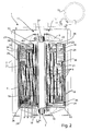
- the optimized single-phase transformer according to the invention used especially for carrying out dielectric tests, is shown in section in figures 1 and 2 , where it is globally indicated with 1.
- the optimized transformer 1 comprises:
- the primary winding 4 comprises a plurality of layers 8 facing each other, defining linear directions Y substantially parallel each other, each of which includes a plurality of elementary coils independent one from another, electrically connected each other.
- the containment case 2 is of the type in itself known in the field here concerned, made for example of metallic material.
- the magnetic core 3 presents shape and composition of the type in itself known in the electrotechnical industry field: in particular, the magnetic core is of the so-called column type and is formed by a plurality of mutually packed laminations with low loss figure.
- the magnetic core 3 presents in longitudinal section a rectangular profile, including two opposite columns 31, 32, on the second of which the windings 4 and 6 are arranged, the columns being reciprocally connected by two yokes 33, 34 which are compressed by core clamps 9, 10 made of metallic material, one of which connected with the containment case 2 through anchorage means, as a whole reported with 11 and the other one supported by a reference plane 12.
- figures 1 and 2 show some of the other traditional member organs of a transformer, for carrying out dielectric tests, also provided in the optimized transformer 1 of the invention, such as the high voltage insulators 13, connected with the primary winding 4, and the low voltage insulators 14, connected with the secondary winding 6.
- expansion reservoir 15 is also shown containing hot oil used as refrigerant fluid and insulator responsible for the disposal of heat generated inside the containment case 2 of the transformer 1.
- the primary winding 4 comprises the aforesaid layers, in this case in number of four, one facing the other.
- the secondary, or low voltage, winding 6 comprises two conductive plates coupled from symmetrically opposite parties to the column 32 of the magnetic core 3.
- the number of layers present in the primary winding will be different from that one indicated above, the same depending on the design choices and the voltage values to be achieved.
- the windings 4 and 6 are magnetically coupled with the column 32 of the magnetic core 3, with the primary winding 4 which surrounds the secondary winding 6 through the interposition of an insulating screen 16 and, consequently, the column 32 of the magnetic core 3 with which it is coaxial.
- linear directions Y defined by the various layers 8 of the primary winding 4 are parallel not only among them but also to the columns 31 and 32 of the magnetic core 3.
- the coils are reciprocally connected in series and arranged one consecutively the other along the tortuous path defined by the layers 8 of the primary winding 4.
- the aforesaid coils include the same number of turns, each of them producing, preferably but not necessarily, a voltage of 20 kV.
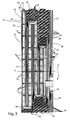
- the optimized transformer 1 also includes a plurality of spacer gates 17 which separate one from the other the coils in each of the layers 8, as figure 3 better highlights.
- each of the layers 8 decreases in gradual and prearranged way, on the basis of the constructive choices, starting from the column 32 of the magnetic core 3 and according to a longitudinal direction X orthogonal to the linear directions Y defined by the layers 8.
- the terminal coil of a layer 8 is electrically connected with the terminal coil of the immediately subsequent layer 8 by means of an intermediate line 18 which splits the voltage up in order to avoid peaks thereof.
- the intermediate line 18 is faced to the ends of each of the layers 8 in order to interpose itself between any layer 8 and the reciprocally opposite core clamps 9, 10 placed inside the containment case 2.
- the last coil of the first layer 8 is connected with the first coil B of the second adjacent layer 8
- the last coil B of the second layer 8 is connected with the first coil C of the third layer 8
- the last coil C of the third layer 8 is connected with the first coil D of the fourth layer 8.
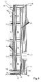
- the intermediate line 18 has a substantially semi-elliptical shape profile 18' which includes a flat surface 18a facing the coils of two layers 8 adjacent and consecutive each other, as it can be seen for example in figure 4 for the coils indicated with C and the coils indicated with D.
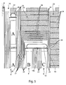
- the intermediate line 18 is also covered with a laminar paper 19, clearly visible in figure 5 , suitable to make equipotential the outer surface 18b of the intermediate line 18.
- the optimized transformer 1 also comprises:
- the low voltage terminal 20 and the full voltage terminal 21 are interposed between one of the layers 8 and one of the core clamps 9, 10.
- the transformer 1 comprises a pressing ring 22 placed close to the low voltage terminal 20 and interposed between the latter and the core clamps 9.
- Such pressing ring 22 also performs the function of laterally protecting the primary winding 4 at the first layer 8.
- the optimized transformer 1 includes a plurality of piles 23 of pressing rings 24, interposed between each of the core clamps 9, 10 and the primary winding 4 and positioned close to the intermediate line 18 and the full voltage terminal 21.
- the height of these piles 23 increases gradually with the decreasing of the height of the layers 8 of the primary winding 4 along the longitudinal direction X and, therefore, with the increase of the lateral distance between the primary winding 4 and the core clamps 9, 10.
- the height of the pile 23 is directly proportional to the voltage which is found in the primary winding 4 passing from the first layer 8, close to the magnetic core 3, to the fourth layer 8, that one farthest from the magnetic core 3.
- the pressing rings 24 of a same pile 23 present variable thickness, provided that the pressing rings 24 of most reduced thickness are positioned in the vicinity of the intermediate lines 18 and the full voltage terminal 21, as it can be better noticed from figures 3-5 .
- the optimized transformer 1 also comprises a plurality of insulating elements 25 suitable to limit the electric field inside the containment case 2, placed side-by-side each other between each of the layers 8 and between the shortest length layer 8 and the containment case 2.
- Each of the insulating elements 25 includes a laminar cylinder made of cardboard, paper or other similar and suitable cellulose-based material, sized so as to endure the mechanical and electrical stresses to which the optimized transformer 1 is subjected.
- the optimized transformer 1 comprises shielding means, overall indicated with 26, interposed among some of the insulating elements 25 and among some of the pressing rings 24 at the intermediate lines 18 and the full voltage terminal 21.
- the shielding means 26 increases the protection of the primary winding 4 from possible electrical discharges, voltage drops, overvoltages and so on since they create among the insulating elements 25 channels which compel such anomalous effects to make a forced and tortuous path which causes dissipation thereof, virtually preventing that they reach the primary winding 4.
- the shielding means 26 comprise, preferably but not necessarily, a plurality of laminar rings 27 and a plurality of laminar caps 28, each opposite and facing the laminar rings 27.
- Each of the laminar rings 27 and each of the laminar caps 28 have, preferably, a substantially L-shaped profile.
- both the laminar rings 27 and the laminar caps 28 are made of cardboard, paper or other material however derived from cellulose.
- the functioning of the single-phase optimized transformer 1 is substantially equivalent to that one of the common transformers nowadays available on the market, to which they refer for the sake of explanatory convenience.
- the features of the optimized transformer 1 are expressed, indeed, in the constructive composition of the winding, especially the high voltage or primary one numbered with 4, which, compared to the known art, allows to limit the harmful effects resulting from an electrical pulse, an overvoltage, a short circuit or similar events on any point of the winding itself.
- the number of layers can vary on the basis of the constructive choices and the electrical power to be developed, that number could be different from that one previously described and illustrated in the appended drawings.
Landscapes
- Engineering & Computer Science (AREA)
- Power Engineering (AREA)
- Coils Or Transformers For Communication (AREA)
- Coils Of Transformers For General Uses (AREA)
- Testing Relating To Insulation (AREA)
Applications Claiming Priority (2)
| Application Number | Priority Date | Filing Date | Title |
|---|---|---|---|
| IT000102A ITVI20080102A1 (it) | 2008-04-30 | 2008-04-30 | Trasformatore ottimizzato, in particolare per l'esecuzione di prove dielettriche. |
| PCT/IT2009/000200 WO2009133584A1 (en) | 2008-04-30 | 2009-04-30 | Optimized transformer, in particular for carrying ou dielectric tests |
Publications (2)
| Publication Number | Publication Date |
|---|---|
| EP2272073A1 EP2272073A1 (en) | 2011-01-12 |
| EP2272073B1 true EP2272073B1 (en) | 2015-04-29 |
Family
ID=40297428
Family Applications (1)
| Application Number | Title | Priority Date | Filing Date |
|---|---|---|---|
| EP20090738584 Active EP2272073B1 (en) | 2008-04-30 | 2009-04-30 | Optimized transformer, in particular for carrying ou dielectric tests |
Country Status (3)
| Country | Link |
|---|---|
| EP (1) | EP2272073B1 (it) |
| IT (1) | ITVI20080102A1 (it) |
| WO (1) | WO2009133584A1 (it) |
Family Cites Families (6)
| Publication number | Priority date | Publication date | Assignee | Title |
|---|---|---|---|---|
| GB877765A (en) * | 1957-05-29 | 1961-09-20 | Smit & Willem & Co Nv | Improvements in and relating to transformers and choking coils |
| US3353129A (en) * | 1965-10-24 | 1967-11-14 | Gen Electric | High voltage electric induction apparatus |
| US3675175A (en) * | 1971-05-10 | 1972-07-04 | Gen Electric | High voltage coil assembly for electric induction apparatus |
| US4352078A (en) * | 1981-02-06 | 1982-09-28 | Electric Power Research Institute, Inc. | Combination static plate and liquid distribution manifold for electrical inductive apparatus |
| DE3243595C2 (de) * | 1982-11-25 | 1985-10-17 | Smit Transformatoren B.V., Nijmegen | Wicklungsanordnung für einen gasgekühlten Transformator |
| DE19809572C2 (de) * | 1998-03-05 | 2000-06-21 | Siemens Ag | Gießharz-Transformator |
-
2008
- 2008-04-30 IT IT000102A patent/ITVI20080102A1/it unknown
-
2009
- 2009-04-30 EP EP20090738584 patent/EP2272073B1/en active Active
- 2009-04-30 WO PCT/IT2009/000200 patent/WO2009133584A1/en not_active Ceased
Also Published As
| Publication number | Publication date |
|---|---|
| EP2272073A1 (en) | 2011-01-12 |
| WO2009133584A1 (en) | 2009-11-05 |
| ITVI20080102A1 (it) | 2009-11-01 |
Similar Documents
| Publication | Publication Date | Title |
|---|---|---|
| EA001096B1 (ru) | Трансформатор/реактор постоянного тока | |
| US9633777B2 (en) | High impedance air core reactor | |
| US7830233B2 (en) | Electrical induction device for high-voltage applications | |
| Werle et al. | Transformers | |
| EP2439755A1 (en) | Dry-type electrical transformer | |
| EP2289080B1 (en) | Optimized shielded transformer, in particular for carrying out dielectric tests | |
| US9583252B2 (en) | Transformer | |
| CN104603891B (zh) | 变压器 | |
| EP2272073A1 (en) | Optimized transformer, in particular for carrying ou dielectric tests | |
| CN219610197U (zh) | 一种大容量低电压有载调压发电机变压器 | |
| WO2024198396A1 (zh) | 大容量低电压有载调压发电机变压器 | |
| EP3400602A1 (en) | Multilayer winding transformer | |
| JP4867053B2 (ja) | リアクトル | |
| KR102882973B1 (ko) | 변압기 | |
| EP3544033B1 (en) | Electromagnetic induction device having a low losses winding | |
| WO2021130819A1 (ja) | 静止誘導器 | |
| JPH0311534B2 (it) | ||
| Chaw | Design Comparison for Rectangular and Round Winding Distribution Transformer (1000kVA) | |
| US1973073A (en) | Electrical apparatus | |
| EP3349225B1 (en) | Core for an electric shunt reactor | |
| US3332050A (en) | Auto-transformer of core-form type having tapped winding disposed between axially spaced sections of high and low voltage windings | |
| CN105655112A (zh) | 有载调压变压器的调压线圈组合结构 | |
| JP3522290B2 (ja) | 円板巻線 | |
| WO2024126099A1 (en) | Power transformer for on-load tap changer application | |
| CN120637061A (zh) | 一种接地地屏、高阻抗有载调压变压器以及安装方法 |
Legal Events
| Date | Code | Title | Description |
|---|---|---|---|
| PUAI | Public reference made under article 153(3) epc to a published international application that has entered the european phase |
Free format text: ORIGINAL CODE: 0009012 |
|
| 17P | Request for examination filed |
Effective date: 20101026 |
|
| AK | Designated contracting states |
Kind code of ref document: A1 Designated state(s): AT BE BG CH CY CZ DE DK EE ES FI FR GB GR HR HU IE IS IT LI LT LU LV MC MK MT NL NO PL PT RO SE SI SK TR |
|
| AX | Request for extension of the european patent |
Extension state: AL BA RS |
|
| DAX | Request for extension of the european patent (deleted) | ||
| REG | Reference to a national code |
Ref country code: DE Ref legal event code: R079 Ref document number: 602009030966 Country of ref document: DE Free format text: PREVIOUS MAIN CLASS: H01F0030100000 Ipc: H01F0027360000 |
|
| GRAP | Despatch of communication of intention to grant a patent |
Free format text: ORIGINAL CODE: EPIDOSNIGR1 |
|
| RIC1 | Information provided on ipc code assigned before grant |
Ipc: H01F 27/32 20060101ALI20141215BHEP Ipc: H01F 27/36 20060101AFI20141215BHEP |
|
| INTG | Intention to grant announced |
Effective date: 20150120 |
|
| GRAS | Grant fee paid |
Free format text: ORIGINAL CODE: EPIDOSNIGR3 |
|
| GRAA | (expected) grant |
Free format text: ORIGINAL CODE: 0009210 |
|
| AK | Designated contracting states |
Kind code of ref document: B1 Designated state(s): AT BE BG CH CY CZ DE DK EE ES FI FR GB GR HR HU IE IS IT LI LT LU LV MC MK MT NL NO PL PT RO SE SI SK TR |
|
| REG | Reference to a national code |
Ref country code: GB Ref legal event code: FG4D |
|
| REG | Reference to a national code |
Ref country code: CH Ref legal event code: EP |
|
| REG | Reference to a national code |
Ref country code: AT Ref legal event code: REF Ref document number: 724833 Country of ref document: AT Kind code of ref document: T Effective date: 20150515 |
|
| REG | Reference to a national code |
Ref country code: IE Ref legal event code: FG4D |
|
| REG | Reference to a national code |
Ref country code: DE Ref legal event code: R096 Ref document number: 602009030966 Country of ref document: DE Effective date: 20150611 |
|
| REG | Reference to a national code |
Ref country code: NL Ref legal event code: VDEP Effective date: 20150429 |
|
| REG | Reference to a national code |
Ref country code: AT Ref legal event code: MK05 Ref document number: 724833 Country of ref document: AT Kind code of ref document: T Effective date: 20150429 |
|
| REG | Reference to a national code |
Ref country code: LT Ref legal event code: MG4D |
|
| PG25 | Lapsed in a contracting state [announced via postgrant information from national office to epo] |
Ref country code: NL Free format text: LAPSE BECAUSE OF FAILURE TO SUBMIT A TRANSLATION OF THE DESCRIPTION OR TO PAY THE FEE WITHIN THE PRESCRIBED TIME-LIMIT Effective date: 20150429 |
|
| PG25 | Lapsed in a contracting state [announced via postgrant information from national office to epo] |
Ref country code: HR Free format text: LAPSE BECAUSE OF FAILURE TO SUBMIT A TRANSLATION OF THE DESCRIPTION OR TO PAY THE FEE WITHIN THE PRESCRIBED TIME-LIMIT Effective date: 20150429 Ref country code: ES Free format text: LAPSE BECAUSE OF FAILURE TO SUBMIT A TRANSLATION OF THE DESCRIPTION OR TO PAY THE FEE WITHIN THE PRESCRIBED TIME-LIMIT Effective date: 20150429 Ref country code: NO Free format text: LAPSE BECAUSE OF FAILURE TO SUBMIT A TRANSLATION OF THE DESCRIPTION OR TO PAY THE FEE WITHIN THE PRESCRIBED TIME-LIMIT Effective date: 20150729 Ref country code: LT Free format text: LAPSE BECAUSE OF FAILURE TO SUBMIT A TRANSLATION OF THE DESCRIPTION OR TO PAY THE FEE WITHIN THE PRESCRIBED TIME-LIMIT Effective date: 20150429 Ref country code: FI Free format text: LAPSE BECAUSE OF FAILURE TO SUBMIT A TRANSLATION OF THE DESCRIPTION OR TO PAY THE FEE WITHIN THE PRESCRIBED TIME-LIMIT Effective date: 20150429 Ref country code: PT Free format text: LAPSE BECAUSE OF FAILURE TO SUBMIT A TRANSLATION OF THE DESCRIPTION OR TO PAY THE FEE WITHIN THE PRESCRIBED TIME-LIMIT Effective date: 20150831 |
|
| PG25 | Lapsed in a contracting state [announced via postgrant information from national office to epo] |
Ref country code: IS Free format text: LAPSE BECAUSE OF FAILURE TO SUBMIT A TRANSLATION OF THE DESCRIPTION OR TO PAY THE FEE WITHIN THE PRESCRIBED TIME-LIMIT Effective date: 20150829 Ref country code: GR Free format text: LAPSE BECAUSE OF FAILURE TO SUBMIT A TRANSLATION OF THE DESCRIPTION OR TO PAY THE FEE WITHIN THE PRESCRIBED TIME-LIMIT Effective date: 20150730 Ref country code: AT Free format text: LAPSE BECAUSE OF FAILURE TO SUBMIT A TRANSLATION OF THE DESCRIPTION OR TO PAY THE FEE WITHIN THE PRESCRIBED TIME-LIMIT Effective date: 20150429 Ref country code: LV Free format text: LAPSE BECAUSE OF FAILURE TO SUBMIT A TRANSLATION OF THE DESCRIPTION OR TO PAY THE FEE WITHIN THE PRESCRIBED TIME-LIMIT Effective date: 20150429 |
|
| REG | Reference to a national code |
Ref country code: CH Ref legal event code: PL |
|
| REG | Reference to a national code |
Ref country code: IE Ref legal event code: MM4A |
|
| PG25 | Lapsed in a contracting state [announced via postgrant information from national office to epo] |
Ref country code: EE Free format text: LAPSE BECAUSE OF FAILURE TO SUBMIT A TRANSLATION OF THE DESCRIPTION OR TO PAY THE FEE WITHIN THE PRESCRIBED TIME-LIMIT Effective date: 20150429 Ref country code: MC Free format text: LAPSE BECAUSE OF FAILURE TO SUBMIT A TRANSLATION OF THE DESCRIPTION OR TO PAY THE FEE WITHIN THE PRESCRIBED TIME-LIMIT Effective date: 20150429 Ref country code: CH Free format text: LAPSE BECAUSE OF NON-PAYMENT OF DUE FEES Effective date: 20150430 Ref country code: LI Free format text: LAPSE BECAUSE OF NON-PAYMENT OF DUE FEES Effective date: 20150430 Ref country code: DK Free format text: LAPSE BECAUSE OF FAILURE TO SUBMIT A TRANSLATION OF THE DESCRIPTION OR TO PAY THE FEE WITHIN THE PRESCRIBED TIME-LIMIT Effective date: 20150429 |
|
| REG | Reference to a national code |
Ref country code: DE Ref legal event code: R097 Ref document number: 602009030966 Country of ref document: DE |
|
| PG25 | Lapsed in a contracting state [announced via postgrant information from national office to epo] |
Ref country code: CZ Free format text: LAPSE BECAUSE OF FAILURE TO SUBMIT A TRANSLATION OF THE DESCRIPTION OR TO PAY THE FEE WITHIN THE PRESCRIBED TIME-LIMIT Effective date: 20150429 Ref country code: SK Free format text: LAPSE BECAUSE OF FAILURE TO SUBMIT A TRANSLATION OF THE DESCRIPTION OR TO PAY THE FEE WITHIN THE PRESCRIBED TIME-LIMIT Effective date: 20150429 Ref country code: PL Free format text: LAPSE BECAUSE OF FAILURE TO SUBMIT A TRANSLATION OF THE DESCRIPTION OR TO PAY THE FEE WITHIN THE PRESCRIBED TIME-LIMIT Effective date: 20150429 Ref country code: RO Free format text: LAPSE BECAUSE OF NON-PAYMENT OF DUE FEES Effective date: 20150429 |
|
| PLBE | No opposition filed within time limit |
Free format text: ORIGINAL CODE: 0009261 |
|
| STAA | Information on the status of an ep patent application or granted ep patent |
Free format text: STATUS: NO OPPOSITION FILED WITHIN TIME LIMIT |
|
| REG | Reference to a national code |
Ref country code: FR Ref legal event code: PLFP Year of fee payment: 8 |
|
| GBPC | Gb: european patent ceased through non-payment of renewal fee |
Effective date: 20150729 |
|
| 26N | No opposition filed |
Effective date: 20160201 |
|
| PG25 | Lapsed in a contracting state [announced via postgrant information from national office to epo] |
Ref country code: IE Free format text: LAPSE BECAUSE OF NON-PAYMENT OF DUE FEES Effective date: 20150430 Ref country code: GB Free format text: LAPSE BECAUSE OF NON-PAYMENT OF DUE FEES Effective date: 20150729 |
|
| PG25 | Lapsed in a contracting state [announced via postgrant information from national office to epo] |
Ref country code: SI Free format text: LAPSE BECAUSE OF FAILURE TO SUBMIT A TRANSLATION OF THE DESCRIPTION OR TO PAY THE FEE WITHIN THE PRESCRIBED TIME-LIMIT Effective date: 20150429 |
|
| PG25 | Lapsed in a contracting state [announced via postgrant information from national office to epo] |
Ref country code: BE Free format text: LAPSE BECAUSE OF FAILURE TO SUBMIT A TRANSLATION OF THE DESCRIPTION OR TO PAY THE FEE WITHIN THE PRESCRIBED TIME-LIMIT Effective date: 20150429 |
|
| PG25 | Lapsed in a contracting state [announced via postgrant information from national office to epo] |
Ref country code: MT Free format text: LAPSE BECAUSE OF FAILURE TO SUBMIT A TRANSLATION OF THE DESCRIPTION OR TO PAY THE FEE WITHIN THE PRESCRIBED TIME-LIMIT Effective date: 20150429 |
|
| REG | Reference to a national code |
Ref country code: FR Ref legal event code: PLFP Year of fee payment: 9 |
|
| PG25 | Lapsed in a contracting state [announced via postgrant information from national office to epo] |
Ref country code: BG Free format text: LAPSE BECAUSE OF FAILURE TO SUBMIT A TRANSLATION OF THE DESCRIPTION OR TO PAY THE FEE WITHIN THE PRESCRIBED TIME-LIMIT Effective date: 20150429 Ref country code: HU Free format text: LAPSE BECAUSE OF FAILURE TO SUBMIT A TRANSLATION OF THE DESCRIPTION OR TO PAY THE FEE WITHIN THE PRESCRIBED TIME-LIMIT; INVALID AB INITIO Effective date: 20090430 |
|
| PG25 | Lapsed in a contracting state [announced via postgrant information from national office to epo] |
Ref country code: SE Free format text: LAPSE BECAUSE OF FAILURE TO SUBMIT A TRANSLATION OF THE DESCRIPTION OR TO PAY THE FEE WITHIN THE PRESCRIBED TIME-LIMIT Effective date: 20150429 Ref country code: CY Free format text: LAPSE BECAUSE OF FAILURE TO SUBMIT A TRANSLATION OF THE DESCRIPTION OR TO PAY THE FEE WITHIN THE PRESCRIBED TIME-LIMIT Effective date: 20150429 |
|
| PG25 | Lapsed in a contracting state [announced via postgrant information from national office to epo] |
Ref country code: LU Free format text: LAPSE BECAUSE OF NON-PAYMENT OF DUE FEES Effective date: 20150430 |
|
| REG | Reference to a national code |
Ref country code: FR Ref legal event code: PLFP Year of fee payment: 10 |
|
| PG25 | Lapsed in a contracting state [announced via postgrant information from national office to epo] |
Ref country code: MK Free format text: LAPSE BECAUSE OF FAILURE TO SUBMIT A TRANSLATION OF THE DESCRIPTION OR TO PAY THE FEE WITHIN THE PRESCRIBED TIME-LIMIT Effective date: 20150429 |
|
| PGFP | Annual fee paid to national office [announced via postgrant information from national office to epo] |
Ref country code: FR Payment date: 20200312 Year of fee payment: 12 |
|
| PGFP | Annual fee paid to national office [announced via postgrant information from national office to epo] |
Ref country code: TR Payment date: 20200430 Year of fee payment: 12 |
|
| PG25 | Lapsed in a contracting state [announced via postgrant information from national office to epo] |
Ref country code: FR Free format text: LAPSE BECAUSE OF NON-PAYMENT OF DUE FEES Effective date: 20210430 |
|
| P01 | Opt-out of the competence of the unified patent court (upc) registered |
Effective date: 20230503 |
|
| PG25 | Lapsed in a contracting state [announced via postgrant information from national office to epo] |
Ref country code: TR Free format text: LAPSE BECAUSE OF NON-PAYMENT OF DUE FEES Effective date: 20210430 |
|
| PGFP | Annual fee paid to national office [announced via postgrant information from national office to epo] |
Ref country code: IT Payment date: 20260210 Year of fee payment: 18 |
|
| PGFP | Annual fee paid to national office [announced via postgrant information from national office to epo] |
Ref country code: DE Payment date: 20260305 Year of fee payment: 18 |