EP2272323A1 - Gerät und Verfahren zum Schneiden von Blumenstengeln - Google Patents
Gerät und Verfahren zum Schneiden von Blumenstengeln Download PDFInfo
- Publication number
- EP2272323A1 EP2272323A1 EP10168709A EP10168709A EP2272323A1 EP 2272323 A1 EP2272323 A1 EP 2272323A1 EP 10168709 A EP10168709 A EP 10168709A EP 10168709 A EP10168709 A EP 10168709A EP 2272323 A1 EP2272323 A1 EP 2272323A1
- Authority
- EP
- European Patent Office
- Prior art keywords
- stem
- hand tool
- cutting
- flower
- stem holder
- Prior art date
- Legal status (The legal status is an assumption and is not a legal conclusion. Google has not performed a legal analysis and makes no representation as to the accuracy of the status listed.)
- Withdrawn
Links
- 238000005520 cutting process Methods 0.000 title claims abstract description 147
- 238000000034 method Methods 0.000 title claims abstract description 12
- 230000007246 mechanism Effects 0.000 claims abstract description 23
- 230000001154 acute effect Effects 0.000 claims abstract description 15
- 230000005540 biological transmission Effects 0.000 claims description 7
- 230000008901 benefit Effects 0.000 description 36
- 238000010276 construction Methods 0.000 description 7
- 230000007935 neutral effect Effects 0.000 description 7
- 239000007788 liquid Substances 0.000 description 3
- 238000004519 manufacturing process Methods 0.000 description 3
- 239000000463 material Substances 0.000 description 2
- 230000008859 change Effects 0.000 description 1
- 238000006073 displacement reaction Methods 0.000 description 1
- 238000001746 injection moulding Methods 0.000 description 1
- 239000002184 metal Substances 0.000 description 1
- 230000008569 process Effects 0.000 description 1
- 230000009467 reduction Effects 0.000 description 1
- 239000002023 wood Substances 0.000 description 1
Images


Classifications
-
- A—HUMAN NECESSITIES
- A01—AGRICULTURE; FORESTRY; ANIMAL HUSBANDRY; HUNTING; TRAPPING; FISHING
- A01G—HORTICULTURE; CULTIVATION OF VEGETABLES, FLOWERS, RICE, FRUIT, VINES, HOPS OR SEAWEED; FORESTRY; WATERING
- A01G3/00—Cutting implements specially adapted for horticultural purposes; Delimbing standing trees
-
- A—HUMAN NECESSITIES
- A01—AGRICULTURE; FORESTRY; ANIMAL HUSBANDRY; HUNTING; TRAPPING; FISHING
- A01G—HORTICULTURE; CULTIVATION OF VEGETABLES, FLOWERS, RICE, FRUIT, VINES, HOPS OR SEAWEED; FORESTRY; WATERING
- A01G5/00—Floral handling
Definitions
- the invention relates to a hand tool for cutting flower stems according to the preamble of claim 1.
- the invention further relates to a method for cutting flower stems using the hand tool according to the preamble of claim 15.
- a European patent application EP0998846 discloses a cutting device for cutting cut flowers.
- This cutting device can be operated by hand by means of a squeezing mechanism.
- the cutting device is furthermore provided with a tube with a funnel.
- the tube is closed on the side opposite the funnel by means of a stop, so that one end of a flower to be cut can rest thereon.
- the stem of the flower to be cut has to be introduced into the tube via the funnel and then rests on the stop.
- a knife is then displaced by squeezing the squeezing mechanism.
- the knife moves in such a way that it cuts the stem at a cutting angle with respect to the longitudinal direction of the stem.
- This cutting device has the drawback that it is not possible to cut accurately at a predetermined desired cutting location.
- a pruner for cutting flower stems is known.
- This pruner is known from patent application GB2305881 and comprises a tubular shaft in which a knife can be displaced in a rectilinear manner. The knife can be displaced up to one end of the tubular shaft. At this end, a recess is provided in the tubular shaft. The recess extends at right angles to the movement of the knife. As a result of the recess in the tubular shaft, an opening is produced for inserting a flower stem to be cut. In a first position, the knife is not situated in the opening. Subsequently, the knife can be displaced in a rectilinear movement, so that the knife is situated in the opening. During said displacement, a flower stem arranged in the opening is cut. The recess is configured such that cutting can take place at any desired cutting location along the flower stem. This pruner has the drawback that it is not possible to cut accurately at a defined cutting angle.
- the drawback of the known pruner and cutting device is the fact that it is not possible to accurately cut a flower stem both at a predetermined cutting location and at a defined cutting angle.
- This hand tool is suitable for cutting a flower stem.
- the flower stem may be elongate.
- the hand tool comprises a squeeze control mechanism for translating a movement of the hand into a movement of a cutting knife.
- the movement of the hand comprises a squeezing and/or pulling movement.
- the hand tool comprises a straight guide for guiding the cutting knife and a stem holder for holding the flower stem.
- the stem holder can be passed through freely and allows the cutting location of the flower stem to be freely selected.
- the stem holder is of an elongate design and is provided with a centre axis in a longitudinal direction in order to keep the flower stem oriented, the centre axis making an acute angle with the straight guide.
- This hand tool has the advantage that it is possible to achieve both a desired cutting angle and a desired cutting location, with it being possible to orient the flower stem during cutting.
- the stem holder can be used to orient the flower stem, it is possible, in addition to the cutting location, to also accurately determine a cutting angle between the centre axis of the flower stem and a cut surface of the flower stem.
- the cut surface is a surface which is cut by the cutting knife and is a cross section of the flower stem transversely to the flower stem.
- An advantage is the fact that the lifespan of the flower can be increased.
- the cutting angle and the cut surface determine the uptake of liquid by the flower.
- the lifespan of the flower can be increased.
- a further advantage is the fact that damage to the flower can be reduced, since the flower stem no longer has to be held after it has been placed in the flower holder.
- the stem holder is elongate and provided with ends which can be passed through freely, for example a tube having a circular or oval cross section.
- the stem holder is open in the longitudinal direction, so that an elongate space is provided.
- the stem holder is channel-shaped, for example.
- the flower stem can be laid into the elongate space. This may either be a tube or channel having a specific shape, for example a U-shaped or a V-shaped channel. This has the advantage that the cutting location along the centre axis of the flower stem can be oriented more accurately and that the flower stem can be cut to size.
- the ends of the stem holder are free, as a result of which the flower stem can be passed freely through the stem holder.
- the stem holder is not provided with a stop at any end. Such a stop can block the ends and make the free passage of the flower stem impossible.
- a further advantage is the fact that it makes it possible to execute a rectilinear cutting movement. This is in contrast to a rotating or scissorlike movement, in which a flower stem has to be compressed before being cut through, which may damage the latter.
- the acute angle between the centre axis of the stem holder and the straight guide can be fixed.
- This has the advantage that successive flower stems can be cut at the same cutting angle.
- An additional advantage is the fact that the lifespan of the flowers of the successive flower stems can substantially be expected to be identical.
- both the straight guide and the centre axis of the stem holder are situated in a horizontal plane in use. This may be the same horizontal plane or parallel horizontal planes. This has the advantage that the user has a better view of the flower stem since the latter can be viewed from above.
- the use comprises at least the cutting of the flower stems.
- the hand tool can be used both with a horizontally arranged straight guide and a horizontally arranged centre axis of the stem holder.
- the cutting knife substantially cuts halfway along the centre axis of the stem holder.
- a distance between the cutting knife and a first end of the stem holder is substantially equal to the distance between the cutting knife and a second end of the stem holder.
- the distance between the cutting knife and the end of the stem holder which is distal from the user is greater than the distance between the cutting knife and the end of the stem holder which is proximal to the user.
- the distance between a desired cut surface and an end of the flower stem which is distal from the flower head will be smaller than the distance between a desired cut surface and an end of the flower stem which is proximal to the flower head.
- the distance between the desired cut surface and the end of the flower stem which is distal from the flower head can be adapted to the distance between the cutting knife and the end of the stem holder which is proximal to the user.
- the flower head can be arranged in such a manner that it is distal from the user. This has the advantage that when the same fixation is used, a shorter stem holder can be used during orientation as the support offered by the stem holder can be used in an optimum manner. This can increase the convenience of the hand tool and result in reductions in material and production costs.
- the acute angle between the centre axis of the stem holder and the straight guide is adjustable.
- the acute angle between the centre axis of the stem holder and the straight guide determines the cutting angle of the flower stem. By adjusting this acute angle, it is also possible to change the cutting angle.
- the stem holder can be designed so as to be rotatable with respect to the straight guide. This has the advantage that the lifespan of various types of flowers after cutting can be increased.
- the stem holder is rotatable with respect to the straight guide.
- the straight guide may have a fixed orientation relative to the squeeze control mechanism.
- the stem holder is then rotatable with respect to the straight guide and the squeeze control mechanism.
- the user grips the hand tool by the squeeze control mechanism. This has the advantage that adjustment of the acute angle may be user-friendly.
- the user can use the other hand to rotate the stem holder relative to the straight guide.
- the hand tool comprises at least a first and a second stem holder.
- the hand tool may also comprise several stem holders. This may be the second stem holder, but also a third, fourth, fifth, etc. This has the advantage that the hand tool can be used for different kinds of flower stems.
- each stem holder can be set to its own cutting angle and its own cutting location on the flower stem.
- the hand tool comprises the first and the second stem holder.
- the second stem holder has a predetermined position and location with respect to the first stem holder.
- the centre axes of the stem holders may be situated parallel to one another, but they can also be at an angle to one another.
- the stem holders can intersect one another, but can also be separate from one another.
- a centre axis of the first stem holder makes an acute angle with a centre axis of the second stem holder.
- Both the centre axis of the first stem holder and the centre axis of the second stem holder make an acute angle with the straight guide. Since the centre axis of the first stem holder makes an angle with the centre axis of the second stem holder, a different cutting angle can be produced, depending on the stem holder into which the flower stem is placed.
- the hand tool can be suitable for several types of flowers, each of which can have a different optimum cutting angle. By means of the hand tool, the flower stem can be cut at a different cutting angle depending on the stem holder into which it is placed.
- a further advantage is that the ease of use can be improved since there are several stem holders, each with a centre axis which makes a different angle with respect to the straight guide.
- a second hand which places the flower stem, can choose into which stem holder the latter should be placed.
- the user can introduce the flower stem into the stem holder into which the flower can be placed most readily by the second hand. This has the further advantage that cutting can be speeded up.
- the centre axis of the first stem holder and the centre axis of the second stem holder are arranged mirror-symmetrically.
- the stem holders which are arranged thus comprise a line of symmetry in which the straight guide is provided.
- Both the first stem holder and the second stem holder are elongate.
- the respective centre axes of the stem holders can therefore bound a plane. If this plane is viewed at right angles, the stem holders are arranged in a certain way with respect to one another. They are in a certain position relative to one another. This arrangement may, viewed at right angles to the plane, be mirror-symmetrical.
- Such a mirror-symmetrical arrangement comprises a line of symmetry in which mirroring takes place. In this line of symmetry, the straight guide is provided, as a result of which the movement of the knife takes place along this line of symmetry. This has the advantage that a compact hand tool can be produced, since the straight guide is situated in the centre of the stem holders.
- the hand tool is suitable for both right-hand and left-hand use.
- the hand tool can be held in the left hand.
- the right hand can then place the flower stem into the stem holder.
- the flower stem can then be cut at a specific angle.
- the left hand can be used to place the flower stem in the stem holder.
- the flower stem can then be cut at the same specific angle as with the first method of use.
- the arrangement is such that the centre axes of the first stem holder and the second stem holder form an X.
- the straight guide is provided at the intersection of the X.
- the intersection is on the line of symmetry.
- the cutting knife cuts the flower stem near the intersection between the first stem holder and the second stem holder.
- the first stem holder and the second stem holder can be made in one piece.
- the first stem holder and the second stem holder can be made in one piece.
- the stem holders can be made from one injection moulding. This has the advantage that the structure of the stem holders is stiffer and stronger. A further advantage is the fact that production can be simplified, thus making it possible to produce the hand tool less expensively.
- the angle between the centre axis of the first stem holder and the centre axis of the second stem holder is adjustable.
- cutting angles can be set. This has the advantage that a greater choice of cutting angles for flower stems can be offered.
- the adjustment of the angle between the centre axis of the first stem holder and the centre axis of the second stem holder is carried out by rotating the first stem holder with respect to the second stem holder, the second stem holder remaining fixed with respect to the straight guide.
- the adjustment of the angle between the centre axis of the first stem holder and the centre axis of the second stem holder is carried out by rotating the second stem holder with respect to the first stem holder, the first stem holder remaining fixed with respect to the straight guide.
- the adjustment of the angle between the centre axis of the first stem holder and the centre axis of the second stem holder is carried out by simultaneously rotating the first stem holder and the second stem holder, both the first stem holder and the second stem holder rotating with respect to the straight guide.
- the angle between the centre axis of the first stem holder and the straight guide remains identical to the angle between the centre axis of the second stem holder and the straight guide, before, during and after said rotation.
- the angle between the centre axis of the stem holder and the straight guide is substantially 30 degrees.
- a flower stem is cut at a cutting angle equal to 30 degrees with respect to the centre axis of the flower stem. This equals a cutting angle of 60 degrees with respect to the centre axis of the flower stem.
- a cutting angle of 30 or 60 degrees is an optimum cutting angle for many kinds of flowers, since this results in an optimum uptake of liquid by the flower.
- the squeeze control mechanism comprises a first handle and a second handle.
- the second handle is hingedly connected to the first handle.
- the squeeze control mechanism comprises a transmission for translating a movement of the handle into the movement of the cutting knife.
- the first handle and the second handle form a pulling mechanism or squeezing mechanism.
- the palm of a first hand can rest on the first handle and the second handle forms a trigger which can be pulled by at least one finger of the first hand.
- the second handle hinges about a hinge point with the first handle. This hinge point may be situated near the ends of the first and second handles.
- the transmission translates the movement of the handle into a movement of the cutting knife, for example by means of a linkage system. This has the advantage that the ease of use can be improved.
- the second handle is situated parallel to the first handle and the second handle is able to perform a rectilinear movement which is translated into a rectilinear movement of the cutting knife by the transmission.
- the squeeze control mechanism comprises a spring which is arranged in such a way that it exerts an opposing force when the handle movement is being executed by the user.
- the neutral position is in particular an open position with a maximum angle between a centre axis in the longitudinal direction of the first handle and a centre axis in the longitudinal direction of the second handle.
- the transmission comprises a draw bar.
- This draw bar is hingedly connected to a handle by means of a first hinge.
- the draw bar is furthermore hingedly connected to the cutting knife by means of a second hinge.
- the first hinge is connected to a handle which may be the first handle or the second handle.
- the draw bar bridges a distance and translates the movement of the handle, which is substantially a rotary movement, into a movement of the cutting knife, which is substantially a rectilinear movement.
- the draw bar can be subjected to tensile load and to compressive load. This has the advantage that the movement of the handle, which is a rotary movement, can result in a rectilinear movement of the cutting knife in both directions of rotation.
- the movement of the handle is a rectilinear movement. This may, for example, be possible by designing the first handle to be parallel to the second handle.
- the draw bar is arranged in such a manner that a movement of the handle in which the maximum angle is reduced results in a cutting movement of the cutting knife.
- the cutting movement is the movement of the cutting knife which is accompanied by the cutting of the flower stem. This has the advantage that the flower stem can be cut by means of a squeezing movement.
- the distance between the hinge point of the first handle and the second handle and the first hinge is substantially constant. This has the advantage that a simple construction can be achieved.
- the centre axis of the stem holder and the straight guide is arranged horizontally.
- the draw bar can be moved in a vertical plane.
- the use comprises the introduction of a flower stem to be cut and/or the cutting of the flower stem to be cut.
- a user operates the squeeze control mechanism and the centre axis of the stem holder is situated substantially in a horizontal plane.
- the straight guide is also situated in an substantially horizontal plane. This may be identical horizontal planes, but can also be parallel horizontal planes.
- the user does not rotate the hand tool during use, but only operates the squeeze control mechanism.
- the draw bar can then be moved in the vertical plane.
- the draw bar is rotatably connected to the cutting knife.
- the cutting knife moves along the straight guide in a rectilinear manner. This has the advantage that a more compact construction can be achieved.
- the hand tool comprises at least a first and a second stem holder.
- a horizontal plane is defined by a centre axis in the longitudinal direction of the first stem holder and a centre axis in the longitudinal direction of the second stem holder.
- the first handle can be placed substantially perpendicularly on the straight guide.
- an operating hand will have a position such that the extended fingers extend horizontally forwards.
- the first handle can be placed substantially parallel to the straight guide.
- an operating hand will have a position such that the extended fingers extend vertically downwards.
- the draw bar in use, is displaceable in a longitudinal direction of the straight guide.
- the straight guide is elongate and defines a longitudinal direction.
- the draw bar is also elongate and also defines a longitudinal direction.
- the squeeze control mechanism for example by squeezing or pulling the first handle and/or the second handle, the movement of the cutting knife can be started.
- the draw bar is displaceable in the longitudinal direction of the straight guide.
- This also comprises a parallel longitudinal direction of the draw bar with respect to the longitudinal direction of the straight guide.
- these longitudinal directions are substantially horizontal.
- the straight guide extends along a prolongation of the squeeze control mechanism.
- the prolongation of the squeeze control mechanism is defined by an arrangement of the first handle and the second handle.
- the prolongation of the squeeze control mechanism comprises a prolongation of the first handle and the second handle. This prolongation may be situated in a line of symmetry of the arrangement of the first handle and the second handle.
- the straight guide extends along this prolongation. This may be both in line with or parallel to the prolongation. This has the advantage that a more compact construction can be achieved which does not protrude.
- the first hinge and the second hinge are provided on the same side of the horizontally arranged stem holder.
- both the straight guide and the stem holder are arranged substantially horizontally.
- Both the straight guide and the centre axis of the stem holder are in a horizontal plane. This may be the same horizontal plane or two horizontal planes arranged parallel to one another.
- the first hinge and the second hinge are on the same side of the horizontal plane in which the centre line of the stem holder is situated.
- the first hinge connects a handle to the draw bar.
- the second hinge connects the cutting knife to the draw bar.
- the first hinge and the second hinge are situated on a different side to the side where the flowers stems are introduced. More preferably, the side on which the first hinge and the second hinge are situated is a lower side and the side on which the flower stems are introduced is an upper side. This has the advantage that when the flower stems are introduced, the draw bar cannot form an obstruction.
- Said method for cutting flower stems with the aid of a hand tool comprises the step of introducing a flower stem to be cut into the stem holder. Furthermore, the method comprises the step of cutting the flower stem to be cut in an oriented manner at a desired cutting angle at a desired cutting location by means of the manual control.
- the flower stem When introducing the flower stem to be cut, the flower stem is placed into the stem holder in such a manner that the flower stem can be cut at a desired cutting location and at a desired cutting angle.
- the flower stem Once the flower stem has been introduced into the stem holder, the flower stem is oriented with respect to the straight guide. Thus, the desired cutting location and the desired cutting angle have been determined.
- the squeeze control mechanism is operated by hand in order to cut the flower stem.
- a hinging movement is translated into a movement of the cutting knife, for example by squeezing using the hand or by moving a trigger. During the cutting operation, it is not necessary to orient the flower stem with the aid of the other hand.
- the cutting knife cuts the flower stem at the desired cutting location and at the desired cutting angle.
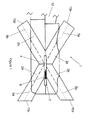
- Fig. 1 the hand tool is denoted overall by reference numeral 1. Furthermore, Fig. 1 shows a first stem holder 2a and a second stem holder 2b which make an acute angle with one another.
- the first stem holder 2a is arranged in an X shape relative to the second stem holder 2b and together they define an intersection 4.
- Both the first stem holder 2a and the second stem holder are elongate and define a first centre axis 5a and a second centre axis 5b, respectively.
- the first stem holder 2a and the second stem holder can be made in one piece.
- first stem holder 2a and the second stem holder 2b can be produced in parts, in which a >-shaped part can be coupled to a ⁇ -shaped part in such a manner that the X-shaped arrangement can be produced. It is also provided that a V-shaped part can be coupled to a ⁇ -shaped part in such a manner that the X-shaped arranged can be produced.
- Fig. 1 shows a straight guide 7 which provides a rectilinear movement of a cutting knife 9.
- the first centre axis 5a and the second centre axis 5b define a first plane. In use, this first plane is preferably a horizontal plane.
- the use comprises introducing the flower stem into the stem holder 2a, 2b and/or operating the hand tool in such a manner that the flower stem is cut.
- the stem holders are shown in the horizontal plane.
- the straight guide 7 is situated substantially parallel to or in this first plane.
- the cutting knife 9 which moves in a rectilinear manner by means of the straight guide 7 cuts a flower stem to be cut at the location of the intersection 4. Since the stem holders 2a, 2b are at an angle to the straight guide 7, the flower stems can be cut at this angle.
- Fig. 1 furthermore shows a first handle 12.
- the first handle 12 extends substantially parallel to the straight guide 7 and is fixed with respect to this straight guide 7.
- a second handle 14 (shown in Figs.
- the stem holder 2a, 2b is designed to be open at the ends 10a, 10b, 10c, 10d, which can make the hand tool 1 suitable for readily introducing flower stems.
- a cutting location along the longitudinal direction of the flower stem to be cut can be freely determined during the introduction of the latter. In this way, the flower stem can be cut to a specific length.
- the cutting angle is defined by the centre axis 5a, 5b of the stem holder 2a, 2b and the straight guide 7 which is of an elongate design.
- Fig. 2 shows the hand tool 1 in the neutral position.
- the neutral position or open position. In the neutral position, the angle between the first handle 12 and the second handle 14 is at its maximum.
- the cutting knife 9 is displaced along the straight guide 7.
- the second handle 14 is hingedly connected to a draw bar 20 by means of a first hinge 17.
- the draw bar is hingedly connected to the cutting knife by means of a second hinge 19.
- the cutting knife 9 comprises a guide 21 which is displaceable in a rectilinear manner in the straight guide 7.
- Fig. 2 shows a cross section of the stem holders 2a, 2b and a first cross section 25, a second cross section 26 and a third cross section 30 of the stem holders 2a, 2b.
- the flower stem is cut at the location of the third cross section which is situated at the intersection 4 of the stem holders 2a, 2b.
- the cutting knife comprises a cutting edge 35 for contacting the flower to be cut in a cutting manner. The cutting edge 35 cuts the flower stem to be cut.
- a second plane is at right angles to the first plane and in the second plane the draw bar 20 and the cutting knife 9 move.
- this second plane is a substantially vertical plane in use.
- the draw bar 20 and the cutting knife 9 are situated in the vertical plane.
- the cutting edge 35 makes an angle with a third plane which is at right angles to both the first plane and the second plane.
- Fig. 3 shows the hand tool 1 in a cutting position or closed position.
- the cutting position is produced by bringing the first handle 12 and the second handle 14 together by means of a hand. During this bringing together or squeezing, the cutting knife 9 is displaced along the straight guide 7 in the direction of the handles 12, 14.
- a minimum angle is achieved between the first handle 12 and the second handle 14. In this case, the minimum angle is substantially 0 degrees, but in other embodiments it may also include other acute angles, such as at least 3, 4 or 5 degrees.
- the hand tool furthermore comprises a spring which exerts an opposing force when the first handle 12 and the second handle 14 are brought together.
- the cutting knife 9 cuts through the third cross section in its entirety, so that a flower stem which has been introduced therein is cut.
- the first handle 12, second handle 14, the movement of the draw bar 20 and the movement of the cutting knife 9 are substantially in the same plane, in this case the preferably vertical second plane.
- the first plane which is bounded by the stem holders 2a, 2b is at right angles to this plane.
- the stem holders 2a, 2b are channel-shaped and have a semicircular cross section 25, 26, 30.
- the stem holder 2a, 2b provides an upper opening along the entire longitudinal direction of the stem holder 2a, 2b.
- the stem holders 2a, 2b such that they have a different cross section, for example U-shaped, V-shaped or O-shaped.
- the cross section of the stem holders 2a, 2b may be both open and closed.
- An open cross section along the longitudinal direction of the stem holder 2a, 2b has the advantage that the flower stem can be introduced into the stem holder 2a, 2b in a simple manner.
- Fig. 4 shows a three-dimensional view of parts of the hand tool. This figure clearly shows that the stem holders 2a, 2b can be made up of several parts. It can be seen that the stem holders are made up of a first part 40 and a second part 41 which define a dividing line 45. The first part 40 and the second part 41 can be coupled together. In addition, Fig. 4 also shows the straight guide 7, which is a recess defined by the first part 40 and the second part. A hinge 46 hingedly connects the first handle 12 to the second handle 14.
- the hand tool may additionally comprise a third, fourth or several stem holders. These may be arranged at a certain angle with respect to one another. When the cutting knife performs a cutting movement, the cutting knife may move away from the user. Provision is also made that a first stem holder does not intersect with a second stem holder. In this case, they do not define a common intersection where the cutting knife cuts, but each of the stem holders provides a separate cross section in which the flower stem is cut by the movement of the cutting knife. A parallel arrangement of the stem holders is possible, for example.
- the stem holders may be made from plastic, but may also be made from wood and/or metal or any other suitable material.
- a hand tool is provided which, in addition to a stem holder whose centre axis makes an acute angle with the straight guide, comprises a stem holder which makes a right angle with the straight guide.
Landscapes
- Life Sciences & Earth Sciences (AREA)
- Environmental Sciences (AREA)
- Biodiversity & Conservation Biology (AREA)
- Ecology (AREA)
- Forests & Forestry (AREA)
- Food-Manufacturing Devices (AREA)
Applications Claiming Priority (1)
| Application Number | Priority Date | Filing Date | Title |
|---|---|---|---|
| NL2003169A NL2003169C2 (nl) | 2009-07-09 | 2009-07-09 | Handgereedschap en werkwijze voor het snijden van bloemstengels. |
Publications (1)
| Publication Number | Publication Date |
|---|---|
| EP2272323A1 true EP2272323A1 (de) | 2011-01-12 |
Family
ID=41665610
Family Applications (1)
| Application Number | Title | Priority Date | Filing Date |
|---|---|---|---|
| EP10168709A Withdrawn EP2272323A1 (de) | 2009-07-09 | 2010-07-07 | Gerät und Verfahren zum Schneiden von Blumenstengeln |
Country Status (2)
| Country | Link |
|---|---|
| EP (1) | EP2272323A1 (de) |
| NL (1) | NL2003169C2 (de) |
Cited By (1)
| Publication number | Priority date | Publication date | Assignee | Title |
|---|---|---|---|---|
| CN110017976A (zh) * | 2019-02-20 | 2019-07-16 | 农业农村部南京农业机械化研究所 | 一种四杆式茎蔓双动刀切割试验装置 |
Citations (6)
| Publication number | Priority date | Publication date | Assignee | Title |
|---|---|---|---|---|
| US3738212A (en) * | 1971-05-14 | 1973-06-12 | R Goodale | Apparatus for trimming the stems of cut flowers |
| US4348832A (en) * | 1981-10-27 | 1982-09-14 | Hauser Allan H | Single flower stem cutter |
| EP0307355A2 (de) * | 1987-09-08 | 1989-03-15 | Paul Roth | Schnittblumenmesser |
| US5261163A (en) * | 1992-07-27 | 1993-11-16 | Shearhart Omer D | Stem cutting device |
| GB2305881A (en) | 1995-10-05 | 1997-04-23 | William George Lyne | Sliding knife pruner |
| EP0998846A2 (de) | 1998-11-04 | 2000-05-10 | Udo Hermanns | Schneidvorrichtung zum Schneiden von Schnittblumen |
-
2009
- 2009-07-09 NL NL2003169A patent/NL2003169C2/nl not_active IP Right Cessation
-
2010
- 2010-07-07 EP EP10168709A patent/EP2272323A1/de not_active Withdrawn
Patent Citations (6)
| Publication number | Priority date | Publication date | Assignee | Title |
|---|---|---|---|---|
| US3738212A (en) * | 1971-05-14 | 1973-06-12 | R Goodale | Apparatus for trimming the stems of cut flowers |
| US4348832A (en) * | 1981-10-27 | 1982-09-14 | Hauser Allan H | Single flower stem cutter |
| EP0307355A2 (de) * | 1987-09-08 | 1989-03-15 | Paul Roth | Schnittblumenmesser |
| US5261163A (en) * | 1992-07-27 | 1993-11-16 | Shearhart Omer D | Stem cutting device |
| GB2305881A (en) | 1995-10-05 | 1997-04-23 | William George Lyne | Sliding knife pruner |
| EP0998846A2 (de) | 1998-11-04 | 2000-05-10 | Udo Hermanns | Schneidvorrichtung zum Schneiden von Schnittblumen |
Cited By (2)
| Publication number | Priority date | Publication date | Assignee | Title |
|---|---|---|---|---|
| CN110017976A (zh) * | 2019-02-20 | 2019-07-16 | 农业农村部南京农业机械化研究所 | 一种四杆式茎蔓双动刀切割试验装置 |
| CN110017976B (zh) * | 2019-02-20 | 2024-03-19 | 农业农村部南京农业机械化研究所 | 一种四杆式茎蔓双动刀切割试验装置 |
Also Published As
| Publication number | Publication date |
|---|---|
| NL2003169C2 (nl) | 2011-01-11 |
Similar Documents
| Publication | Publication Date | Title |
|---|---|---|
| US7716840B2 (en) | Tubing cutter | |
| US5366466A (en) | Surgical scissors | |
| US11141181B2 (en) | Surgical instrument | |
| CN102131381A (zh) | 具有两个轴的机械化便携式电动工具 | |
| US20140311203A1 (en) | Surgical rod bending system and method | |
| US20070101582A1 (en) | Ergonomic handle for scissors and other tools | |
| US20060212045A1 (en) | Surgical suture cutter | |
| ATE392995T1 (de) | Verlängerungsstiel zum betätigen eines handwerkzeugs | |
| DE602004002630T2 (de) | Schwenkbare Griffanordnung für ein Kraftwerkzeug | |
| EP2272323A1 (de) | Gerät und Verfahren zum Schneiden von Blumenstengeln | |
| KR101875068B1 (ko) | 애완동물 발톱 관리장치 | |
| EP1763986A3 (de) | Stiftapparate und Methoden | |
| CN102058431B (zh) | 用于医疗器械的操作装置 | |
| US5469762A (en) | Device for stripping electric conductors and/or wires | |
| US20160059229A1 (en) | Pipetting system with improved control and volume adjustment | |
| CN111226623B (zh) | 一种篱笆树枝剪 | |
| US11212965B1 (en) | Tool for deep selective pruning of branches and vines | |
| US7913394B2 (en) | Cable sheath splitter | |
| JP2004174245A5 (de) | ||
| CN208114627U (zh) | 一种医疗用钳具 | |
| WO2014182654A1 (en) | Forceps with continuous latch | |
| US11672256B2 (en) | Oyster shucking clamp apparatus and method | |
| DE102021119618B4 (de) | Eingabeeinheit für ein medizinisches Instrument sowie medizinisches System mit einer Eingabeeinheit | |
| CN223958872U (zh) | 克氏针塑型剪 | |
| CN107027527A (zh) | 一种便捷修剪树木枝叶的装置 |
Legal Events
| Date | Code | Title | Description |
|---|---|---|---|
| PUAI | Public reference made under article 153(3) epc to a published international application that has entered the european phase |
Free format text: ORIGINAL CODE: 0009012 |
|
| AK | Designated contracting states |
Kind code of ref document: A1 Designated state(s): AL AT BE BG CH CY CZ DE DK EE ES FI FR GB GR HR HU IE IS IT LI LT LU LV MC MK MT NL NO PL PT RO SE SI SK SM TR |
|
| AX | Request for extension of the european patent |
Extension state: BA ME RS |
|
| 17P | Request for examination filed |
Effective date: 20110712 |
|
| STAA | Information on the status of an ep patent application or granted ep patent |
Free format text: STATUS: THE APPLICATION IS DEEMED TO BE WITHDRAWN |
|
| 18D | Application deemed to be withdrawn |
Effective date: 20160202 |