EP2272623A1 - Appareil et procédé d'insertion de joint coulisseau de vitre - Google Patents
Appareil et procédé d'insertion de joint coulisseau de vitre Download PDFInfo
- Publication number
- EP2272623A1 EP2272623A1 EP10007019A EP10007019A EP2272623A1 EP 2272623 A1 EP2272623 A1 EP 2272623A1 EP 10007019 A EP10007019 A EP 10007019A EP 10007019 A EP10007019 A EP 10007019A EP 2272623 A1 EP2272623 A1 EP 2272623A1
- Authority
- EP
- European Patent Office
- Prior art keywords
- wheel
- roller
- extrusion
- weatherstrip
- weatherstripping
- Prior art date
- Legal status (The legal status is an assumption and is not a legal conclusion. Google has not performed a legal analysis and makes no representation as to the accuracy of the status listed.)
- Withdrawn
Links
- 238000003780 insertion Methods 0.000 title claims abstract description 94
- 230000037431 insertion Effects 0.000 title claims abstract description 94
- 238000000034 method Methods 0.000 title claims description 14
- 238000001125 extrusion Methods 0.000 claims abstract description 98
- 230000005540 biological transmission Effects 0.000 claims abstract description 23
- 230000007246 mechanism Effects 0.000 claims description 6
- 230000008878 coupling Effects 0.000 claims description 4
- 238000010168 coupling process Methods 0.000 claims description 4
- 238000005859 coupling reaction Methods 0.000 claims description 4
- 238000007789 sealing Methods 0.000 claims description 3
- 238000011144 upstream manufacturing Methods 0.000 claims 1
- 238000004519 manufacturing process Methods 0.000 description 12
- 230000000712 assembly Effects 0.000 description 6
- 238000000429 assembly Methods 0.000 description 6
- 244000208734 Pisonia aculeata Species 0.000 description 4
- 230000008569 process Effects 0.000 description 4
- 125000006850 spacer group Chemical group 0.000 description 2
- 230000006835 compression Effects 0.000 description 1
- 238000007906 compression Methods 0.000 description 1
- 239000000463 material Substances 0.000 description 1
- 238000012986 modification Methods 0.000 description 1
- 230000004048 modification Effects 0.000 description 1
- 229920003023 plastic Polymers 0.000 description 1
- 239000004033 plastic Substances 0.000 description 1
- 230000001360 synchronised effect Effects 0.000 description 1
- 229920002554 vinyl polymer Polymers 0.000 description 1
Images


Classifications
-
- B—PERFORMING OPERATIONS; TRANSPORTING
- B23—MACHINE TOOLS; METAL-WORKING NOT OTHERWISE PROVIDED FOR
- B23P—METAL-WORKING NOT OTHERWISE PROVIDED FOR; COMBINED OPERATIONS; UNIVERSAL MACHINE TOOLS
- B23P19/00—Machines for simply fitting together or separating metal parts or objects, or metal and non-metal parts, whether or not involving some deformation; Tools or devices therefor so far as not provided for in other classes
- B23P19/04—Machines for simply fitting together or separating metal parts or objects, or metal and non-metal parts, whether or not involving some deformation; Tools or devices therefor so far as not provided for in other classes for assembling or disassembling parts
- B23P19/047—Machines for simply fitting together or separating metal parts or objects, or metal and non-metal parts, whether or not involving some deformation; Tools or devices therefor so far as not provided for in other classes for assembling or disassembling parts for flexible profiles, e.g. sealing or decorating strips in grooves or on other profiles by devices moving along the flexible profile
-
- Y—GENERAL TAGGING OF NEW TECHNOLOGICAL DEVELOPMENTS; GENERAL TAGGING OF CROSS-SECTIONAL TECHNOLOGIES SPANNING OVER SEVERAL SECTIONS OF THE IPC; TECHNICAL SUBJECTS COVERED BY FORMER USPC CROSS-REFERENCE ART COLLECTIONS [XRACs] AND DIGESTS
- Y10—TECHNICAL SUBJECTS COVERED BY FORMER USPC
- Y10T—TECHNICAL SUBJECTS COVERED BY FORMER US CLASSIFICATION
- Y10T29/00—Metal working
- Y10T29/53—Means to assemble or disassemble
- Y10T29/53657—Means to assemble or disassemble to apply or remove a resilient article [e.g., tube, sleeve, etc.]
-
- Y—GENERAL TAGGING OF NEW TECHNOLOGICAL DEVELOPMENTS; GENERAL TAGGING OF CROSS-SECTIONAL TECHNOLOGIES SPANNING OVER SEVERAL SECTIONS OF THE IPC; TECHNICAL SUBJECTS COVERED BY FORMER USPC CROSS-REFERENCE ART COLLECTIONS [XRACs] AND DIGESTS
- Y10—TECHNICAL SUBJECTS COVERED BY FORMER USPC
- Y10T—TECHNICAL SUBJECTS COVERED BY FORMER US CLASSIFICATION
- Y10T29/00—Metal working
- Y10T29/53—Means to assemble or disassemble
- Y10T29/5367—Coupling to conduit
-
- Y—GENERAL TAGGING OF NEW TECHNOLOGICAL DEVELOPMENTS; GENERAL TAGGING OF CROSS-SECTIONAL TECHNOLOGIES SPANNING OVER SEVERAL SECTIONS OF THE IPC; TECHNICAL SUBJECTS COVERED BY FORMER USPC CROSS-REFERENCE ART COLLECTIONS [XRACs] AND DIGESTS
- Y10—TECHNICAL SUBJECTS COVERED BY FORMER USPC
- Y10T—TECHNICAL SUBJECTS COVERED BY FORMER US CLASSIFICATION
- Y10T29/00—Metal working
- Y10T29/53—Means to assemble or disassemble
- Y10T29/53678—Compressing parts together face to face
Definitions
- the present invention relates to an apparatus and a method whereby weatherstripping is inserted into a member which may be used to provide components from which windows and other fenestration products may be fabricated, and particularly to an apparatus and a method for insertion of weatherstripping in-line with the production of the members from which the frames may be fabricated, rather than offline into such members.
- the on-line insertion of the weatherstripping providing savings in manufacturing costs in the fabrication of the windows over offline weatherstrip insertion.
- the invention provides an apparatus and a method for inserting weatherstripping into a slot in a member (or extrusion) from which frame components of windows may be fabricated as the member is produced and moves in a linear path away from the production equipment, such as an extruder in which the extrusion is formed.
- a roller is pressed against the side of the member or extrusion so that the roller is rotated by the member as it moves along the path away from the extruder towards a cutting station, a transmission transfers rotary motion from the roller to an insertion wheel so that the wheel is driven at a speed where the weatherstripping driven by the wheel moves at least at the same speed as the extrusion.
- the weatherstripping When the extrusion reaches a cutting station, the weatherstripping is not pulled back and is in alignment with the end of the member which is cut off into sections. Such sections may be called lineals and are sold, as products by the extrusion manufacturer with inserted weatherstripping, to fabricators of windows and other fenestration products. When the weatherstripping is smaller in cross-sectional area than the T-slot in the lineals and can slip therein, the fabricator can readily adjust the position of the weatherstripping in the slot to facilitate manufacture of windows and doors.
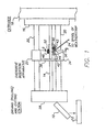
- FIGs. 1 and 2 there is shown apparatus for producing lineals which are extrusion sections 10 shown dropping into a carriage 12 and which may contain a plurality of said such sections which are cut from an extrusion 14 fed from the tank 16 of an extruder 18.
- the extrusion profile is formed by dies (not shown) which define the cross sectional shape or profile of the extrusion 14. While one extrusion is being shown, two may desirably be made simultaneously, the other not being shown in the drawing to simplify the illustration.
- Support legs 20 support an overdrive insertion apparatus 22 which inserts weatherstripping 24, which is pulled from a reel continuously as the extrusion is produced.
- This weatherstripping 24 is inserted by the apparatus 22 into a slot in the weatherstripping which is a T-slot of the type shown, for example, in the above referenced Hope, Socci, and Albanese patents and also at 26 in FIG. 7 .
- the extrusion 14 has cooled and the profile thereof is fixed by the time the extrusion moves from the extruder to the insertion apparatus 22.
- the extrusion 14 is driven (pulled out of the extruder 18), for example, by rollers which clamp the side surfaces thereof and cut at a driving, pulling, and cutting station 28.
- the driving station may include the pulling rollers and a cutter, where the cutter may be a cutting wheel, spaced downstream from the driving rollers so that the driving rollers remain in contact with extrusions after they are cut off by the cutter.
- the driving and cutting facilities may be similar to those shown in the Albanese patent ( FIG. 1 thereof).
- the extrusion 14 is therefore advanced in the downstream direction (toward the left of FIG. 1 ) at a constant speed.
- the insertion apparatus 22 is mounted on an assembly of plates 42, 36A and 36B and spacer 37.
- This assembly is carried on a support plate 34.
- a set of rods 30 are threaded into holes (not shown) in the plate 34 and mount the plate 34 to the support legs 20 or another plate 32 (as shown) mounted on the legs 20.
- the support plate 36a supports an upright member 38 having guide holes 40 through which the extrusion 14 passes and is supported.
- the hole 40 on the right in the upright 38 is for another extrusion not shown in the illustration.
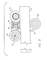
- Carried on the support plate 36a is a plate 42 which mounts a weatherstrip insertion wheel 44 and rubber tired rollers 46 and 48 which engage opposite sides of the extrusion 14 and are rotated by the extrusion.
- the rotation of the rollers 46 and 48, as they are driven by the moving extrusion 14, is transferred to the insertion wheel 44 by gear transmissions in arms 50 and 52 which are pivotable about the rotation axis of the roller 46 and are yieldably biased toward each other so as to press against the opposite sides of the extrusion 14.
- the assembly of wheel 44, rollers 46, and the pivotal arms 50 and 52 is mounted on a post 43 connected to the support plate 36 and on which the wheel 44 is journaled for rotation, as shown in FIG. 2 .
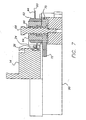
- the wheel 44 has a disk section 60 extending from a sleeve 62, which is press fit on a collar 64 (see FIG. 7 ).
- a bushing 66 is rotatable on a shaft 68.
- a drive gear 70 is press fit between the bushing 66 and the collar 64.
- the wheel 44 including its disk 60, sleeve 62, and collar 64 all are rotated by the drive gear.
- the drive gear is connected to a spur gear 81 (see also FIG. 10 ) which is part of a gear train transmission which couples the rotation of the rollers, via gears 74 and 76 and which rotate with the rollers 46 and 48.
- This transmission includes a gear train 78 between the rollers 46 and 48 in the arm 52 and a gear train 80 between the wheel 44 and the roller 46 in the arm 50.
- the gear 76 which is coupled to the wheel 44 is common to both gear trains and locks both gear trains in driving relationship.
- the gear ratios are selected so that the wheel rotates at a rotational velocity which makes its tangential velocity equal to or slightly greater than the lineal velocity of the extrusion 14. This ensures that the weatherstripping 24 will be driven faster than the feed velocity of the extrusion and will extend up to and in alignment with or past in the downstream direction the end of the extrusion which is cut off at the driving and cutting station 28 ( FIG. 1 ).
- the rollers 46 and 48 are of the same diameter, and are provided by compliant (rubber) rings on sleeves rotatable on bushings, as shown in FIG. 8 .
- the bushings journal the sleeves of the rollers in the arm 52 as shown in FIG. 8 .
- the arms 50 and 52 are pivotably mounted on the axis of the shaft carrying the roller 46.
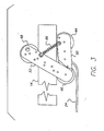
- the arms 50 and 52 are yieldably biased toward each other by an interconnecting spring 86 as shown in FIG. 3 .
- the arms are pivoted away from the extrusion 14 to allow the extrusion to pass between the rollers 46 and 48 and also between the roller 48 and the insertion wheel 44.
- the tension in the compression spring 86 is sufficient to continuously press the rollers 46 and 48 against opposite sides of the extrusion 14 and to hold the wheel 44 in the slot in the extrusion so as to snap the weatherstrip 24 backing into the slot 26 and hold it in the wide part or base of the T portion thereof.
- the wheel 44 then drives weatherstripping 24 at a speed equal to or slightly greater than the speed of the extrusion 14.
- the weatherstrip 24 is movable (slippable) lengthwise of the extrusion since the base of the weatherstrip is slightly smaller than the bottom of the T-slot 26. This assures that the weatherstrip will not pull back at the end where it is cut off by the cutter in the cutting station 28.
- Rotation of the rollers is coupled to the insertion wheel by transmissions provided by gear trains carried in the arms 50 and 52 so that the weatherstripping 24 is driven at the same or slightly greater lineal speed than the speed at which the extrusion 14 moves towards the cutting station 28, thereby assuring that the weatherstrip 24 reaches the cutter in the cutting station simultaneously with the extrusion 14 at the cutter and is not pulled back, which would be the case if the insertion wheel was not rotationally coupled to the rollers and moved at a slower speed than the extrusion due to friction which retards the rotation of the wheel.
- the cut sections of extrusion 14 are filled (substantially aligned at ends of sections) or overfilled (extend past ends of sections) with weatherstripping 24 along their entire length to facilitate the use thereof by the fabricator in providing components of the frames of the windows being fabricated. Accordingly, weatherstrip 24 is inserted on-line and sections 10 (lineals) of the extrusion are produced continually with weatherstrip 24 inserted as the extrusions 14 are fed from the extruder 18.
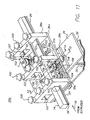
- FIGS. 11-20 provides an overdrive insertion apparatus 22a which inserts weatherstripping 24 into extrusions 24a and assures non-slip operation of the insertion apparatus as well as flexibility of the apparatus in accommodating extrusions 14 of various profiles (cross-sectional shapes).
- FIGS. 11-20 contains components and parts similar to the components and parts of the insertion apparatus 22 described in connection with FIGS. 1-10 , these parts and components are identified with like reference numerals.
- the extrusion member pulled from the extruder 18 is guided in openings of three guide plates 38a, b, and c. Only one extrusion member 14 is illustrated. Another extrusion member may be accommodated in the openings of the guide plates along side the openings through which the extrusion member 14 is guided and driven by the driving (pulling) and cutting station 28 ( FIG. 1 ).
- the guide plates 38a, b, and c have upper and lower sections, the upper section being removable for locating the extrusions 14 and then clamped in place by threaded rods which extend into the support plate 36a and are held in clamped relationship thereon by threaded rods having sets of three knobs 100 thereon.
- the weatherstripping 24 having its pile sealing member on a backing is located with one edge of the backing in the T-slot 26 as shown in FIG. 13 .
- the insertion apparatus both inserts and drives the weatherstrip so that the backing of the weatherstrip is captured in the T-slot as shown in FIG. 14 .
- the weatherstrip then remains in the T-slot. Because the weatherstrip is overdriven at a speed higher than the speed at which the extrusion 14 is driven (for example 30% higher or faster in speed), the weatherstripping remains aligned with the ends of the sections or lineals of the extrusion as they are cut off in the station 28, as explained above in connection with FIGS. 1-10 .
- the improvements in the extrusion apparatus by virtue of the overdrive of the weatherstrip 24 with respect to the extrusion is discussed above in connection with the embodiment of the insertion apparatus illustrated in FIGS. 1-10 .
- the insertion apparatus has a pair of insertion drive assemblies which are similar and insert the weatherstrip 24 into a pair of extrusion members at the same time. Only one of these assemblies 102 is described in detail herein. These assemblies include a drive wheel or roller 104 which engages the extrusion 14 and an insertion wheel or roller 106 which engages the weatherstrip 24.
- the weatherstrip enters the apparatus from the left and may be unwound from a reel thereof.
- the weatherstrip is guided by fingers 107 extending inwardly of the openings in the guide plates 38a, b, and c (see FIG. 11 ).
- the pressure roller assembly 108 which is disposed on the opposite side of the extrusion from the drive wheel or roller 104 and in line with the axis of rotation of the insertion roller 104 (see also FIG. 15 ). Both the insertion wheel and roller assembly 102, and the pressure roller assembly 104 are mounted on a support plate 112 which is assembled on the underplate 36 by fastener bolts 114. The plate 36 and the beam 37 may be mounted on a screw assembly 118 on the lower plate 36b so as to enable the vertical height of the entire insertion apparatus 22a to be adjusted.
- the insertion drive assembly 102 is pivotable about the axis of rotation of the drive roller 104 or an axis parallel thereto so as to adjust the position of the insertion wheel 106.
- the drive roller 104 is rotatable on a shaft 130 fastened by a bolt 131 to the plate 112 the entire assembly is pivotable about the axis of the shaft 130.
- the pressure roller assembly 108 is movable laterally toward and away from the axis of rotation of the drive roller 104 and its drive wheel 126. Se especially FIGS. 15 , 18 , and 19 so as to clamp the extrusion between the drive roller 104 and the pressure roller 108.
- the pressure roller 108 may be a rubber tired roller. As shown in FIG.
- this roller is mounted rotatably in a block 116 which is movable in a dove-tail slot of a support 118 so as to be adjustable by means of a threaded shaft 120 having a knob 122 which is locked in adjusted position by a wing nut 124.
- the drive roller assembly 104 includes the wheel or roller 126 which engages the side of the extrusion 14 along the periphery of the roller. This periphery may be knurled. Also, the driving wheel 126 may be greater in height or width than shown in FIG. 15 to accommodate different profiles of the extrusion members which are handled by the apparatus 22a.
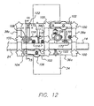
- the insertion drive assembly 102 is also shown in FIGS. 16 and 17 .
- the insertion wheel assembly 106 is rotatable on a shaft 132
- the drive wheel or roller assembly 104 is rotatable on shafts 130.
- These shafts are held by arrangements of bushings 134 and retaining rings 136, as well as other shims and bushings 138 between bars or blocks 140.
- These blocks 140 are held in spaced relationship in the assembly by a spacer bar 142.
- the shafts 130 and 132 are disposed inside of bushings 150 which may be made up of stacks of discs.
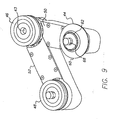
- the drive wheel 126 and a rotary saw blade 152 which provides the insertion wheel assembly are disposed in force-fit relationship with pulleys 154 and 156. These may be ribbed timing pulleys.
- a timing belt 158 is entrained around these pulleys. The pulleys and the timing belt serve as a transmission for transferring the rotation of the drive wheel 126 to the insertion wheel 106.
- the diameter of the pulley of the insertion wheel assembly 106 is larger than the diameter of the pulley 154 of the drive roller assembly 104.
- the diameter of the pulley of the insertion wheel assembly 106 may be 2 inches, while the drive roller pulley 154 diameter may be 1.625 inches. Both the differences in diameter of the pulleys 154 and 156 and the differences in diameter of the drive wheel 126 and the insertion wheel 152 contribute to the amount of overdrive.
- the overdrive provides for the weatherstrip 24 moving 30% faster than the extrusion 14. It will be apparent from FIGS.
- the insertion wheel assembly 106 and the drive wheel assembly 104 are provided by sandwiching the insertion disc 152 (the rotary saw blade) between discs 160 of the insertion wheel assembly 106 (see also FIG. 20 ).
- the flanged cylinders which make up the pulleys 154 and 156 and the drive wheel 126 as well as the discs 160 of the insertion wheel assembly 106 may also be held together by force-fit, and with additional bolts 162 in the case of the saw blade 152 which provides the insertion wheel.
- the insertion drive assembly 102 is pivoted by an adjusting bolt 170 which is turned by a knob 172.
- the angle to which the assembly 102 is pivoted provides for the location of the insertion wheel into the T-slot so as to bring the weatherstrip 24 into captured relationship with the extrusion 14 in the slot 26.
- the drive assembly 102 is locked in place by the pull down bolt arrangement 174 which passes through slots in the locks 140 and is screwed with the aide of a knob 176 into the plate 112.
- the pressure roller assembly 108 is then clamped in place and the apparatus 22a is ready for continual operation as the extrusions are produced in the extruder and pulled to the insertion apparatus by the pulling mechanism in the station 28 (see FIG. 1 ).
Landscapes
- Engineering & Computer Science (AREA)
- Mechanical Engineering (AREA)
- Extrusion Moulding Of Plastics Or The Like (AREA)
Applications Claiming Priority (1)
| Application Number | Priority Date | Filing Date | Title |
|---|---|---|---|
| US12/459,800 US8307524B2 (en) | 2009-07-08 | 2009-07-08 | Weatherstrip insertion apparatus and method |
Publications (1)
| Publication Number | Publication Date |
|---|---|
| EP2272623A1 true EP2272623A1 (fr) | 2011-01-12 |
Family
ID=42646318
Family Applications (1)
| Application Number | Title | Priority Date | Filing Date |
|---|---|---|---|
| EP10007019A Withdrawn EP2272623A1 (fr) | 2009-07-08 | 2010-07-07 | Appareil et procédé d'insertion de joint coulisseau de vitre |
Country Status (3)
| Country | Link |
|---|---|
| US (1) | US8307524B2 (fr) |
| EP (1) | EP2272623A1 (fr) |
| CA (1) | CA2708850A1 (fr) |
Cited By (1)
| Publication number | Priority date | Publication date | Assignee | Title |
|---|---|---|---|---|
| IT202100016100A1 (it) * | 2021-06-21 | 2022-12-21 | Kompany S R L | Sistema di montaggio di un infisso con guarnizione interna e prodotto così ottenuto |
Families Citing this family (6)
| Publication number | Priority date | Publication date | Assignee | Title |
|---|---|---|---|---|
| US8322005B2 (en) * | 2008-10-23 | 2012-12-04 | Pow Specialty Equipment Inc. | Weather strip installation device |
| US9090151B2 (en) | 2010-09-13 | 2015-07-28 | Ultrafab, Inc. | System, method and apparatus for producing weatherstrip containing profiles of different shape and weatherstrips for use therewith |
| US9120369B2 (en) * | 2011-12-19 | 2015-09-01 | Fca Us Llc | Glass run installation tool |
| CA3044369A1 (fr) * | 2018-05-28 | 2019-11-28 | 9320-2240 Quebec Inc. | Systeme et methode d'installation de joints sur des cadres de suppport |
| DE102020118940A1 (de) * | 2020-07-17 | 2022-01-20 | Aytec Automation Gmbh | Vorrichtung zum Applizieren eines Gummiprofils |
| CN115106754B (zh) * | 2021-03-22 | 2023-09-19 | 中冶宝钢技术服务有限公司 | 一种布袋除尘器笼骨的拉拔装置及工艺 |
Citations (8)
| Publication number | Priority date | Publication date | Assignee | Title |
|---|---|---|---|---|
| US4528736A (en) | 1984-06-04 | 1985-07-16 | Schlegel Canada Inc. | Weatherstrip installation apparatus |
| EP0152123A2 (fr) * | 1984-01-10 | 1985-08-21 | Konings Machinefabriek B.V. | Dispositif pour le montage en continu du pied d'ancrage d'une bande d'étancheité dans une ouverture allongée |
| DE3405512A1 (de) * | 1984-02-16 | 1985-08-29 | Paul Anton GmbH, 6603 Sulzbach | Verfahren und vorrichtung zum formschluessigen eindruecken von dichtungsprofilen in rahmenprofile |
| US4843701A (en) | 1986-07-18 | 1989-07-04 | General Motors Corporation | Apparatus of a robot for installing weather stripping in a door or like opening |
| US5103547A (en) | 1991-03-01 | 1992-04-14 | Emco Specialties, Inc. | Apparatus and method for placing weather stripping in a channel |
| US5979036A (en) | 1996-07-19 | 1999-11-09 | Schlegel Corporation | Pile weatherstripping insertion and staking tool |
| WO2002020247A1 (fr) * | 2000-09-05 | 2002-03-14 | Technoplast Kunststofftechnik Gmbh | Procede et dispositif pour produire des profiles en matiere plastique |
| US6385833B1 (en) | 2000-09-06 | 2002-05-14 | Ultrafab, Inc. | Apparatus for installing weatherstripping into frames |
Family Cites Families (8)
| Publication number | Priority date | Publication date | Assignee | Title |
|---|---|---|---|---|
| US3027629A (en) * | 1955-03-21 | 1962-04-03 | Curtis Companies Inc | Apparatus for securing rubber-like weather stripping |
| US3335487A (en) * | 1965-06-25 | 1967-08-15 | Storm Weather Products Co Inc | Machine for inserting pile weather stripping into grooves of storm window extrusions |
| IE48952B1 (en) * | 1978-10-13 | 1985-06-26 | Schlegel Uk Ltd | Method and apparatus for inserting weatherstrip or the like in a groove |
| US4377893A (en) * | 1980-12-29 | 1983-03-29 | Schlegel Corporation | Apparatus and method for aligning a weatherstrip guideway with a receiving slot |
| US4620354A (en) * | 1985-05-28 | 1986-11-04 | General Motors Corporation | Method of applying weatherstrip to a vehicle body opening |
| DE3709412A1 (de) * | 1987-03-21 | 1988-09-29 | Agfa Gevaert Ag | Verfahren und vorrichtung zum anbringen einer klammer an einem schleppband |
| US5179774A (en) * | 1990-05-24 | 1993-01-19 | Ford Motor Company | Apparatus and method for mechanically applying a sealing strip |
| US7017268B2 (en) * | 2003-10-23 | 2006-03-28 | Skf Usa Inc. | Seal reforming method and apparatus |
-
2009
- 2009-07-08 US US12/459,800 patent/US8307524B2/en not_active Expired - Fee Related
-
2010
- 2010-07-07 CA CA2708850A patent/CA2708850A1/fr not_active Abandoned
- 2010-07-07 EP EP10007019A patent/EP2272623A1/fr not_active Withdrawn
Patent Citations (8)
| Publication number | Priority date | Publication date | Assignee | Title |
|---|---|---|---|---|
| EP0152123A2 (fr) * | 1984-01-10 | 1985-08-21 | Konings Machinefabriek B.V. | Dispositif pour le montage en continu du pied d'ancrage d'une bande d'étancheité dans une ouverture allongée |
| DE3405512A1 (de) * | 1984-02-16 | 1985-08-29 | Paul Anton GmbH, 6603 Sulzbach | Verfahren und vorrichtung zum formschluessigen eindruecken von dichtungsprofilen in rahmenprofile |
| US4528736A (en) | 1984-06-04 | 1985-07-16 | Schlegel Canada Inc. | Weatherstrip installation apparatus |
| US4843701A (en) | 1986-07-18 | 1989-07-04 | General Motors Corporation | Apparatus of a robot for installing weather stripping in a door or like opening |
| US5103547A (en) | 1991-03-01 | 1992-04-14 | Emco Specialties, Inc. | Apparatus and method for placing weather stripping in a channel |
| US5979036A (en) | 1996-07-19 | 1999-11-09 | Schlegel Corporation | Pile weatherstripping insertion and staking tool |
| WO2002020247A1 (fr) * | 2000-09-05 | 2002-03-14 | Technoplast Kunststofftechnik Gmbh | Procede et dispositif pour produire des profiles en matiere plastique |
| US6385833B1 (en) | 2000-09-06 | 2002-05-14 | Ultrafab, Inc. | Apparatus for installing weatherstripping into frames |
Cited By (1)
| Publication number | Priority date | Publication date | Assignee | Title |
|---|---|---|---|---|
| IT202100016100A1 (it) * | 2021-06-21 | 2022-12-21 | Kompany S R L | Sistema di montaggio di un infisso con guarnizione interna e prodotto così ottenuto |
Also Published As
| Publication number | Publication date |
|---|---|
| US20110308054A1 (en) | 2011-12-22 |
| CA2708850A1 (fr) | 2011-01-08 |
| US8307524B2 (en) | 2012-11-13 |
Similar Documents
| Publication | Publication Date | Title |
|---|---|---|
| US8307524B2 (en) | Weatherstrip insertion apparatus and method | |
| DE8426496U1 (de) | Vorrichtung zum bearbeiten der randbereiche tafelfoermiger elemente | |
| CN110802644B (zh) | 自动计米切管装置 | |
| CN108545921B (zh) | 一种玻璃切割装置 | |
| CN214393404U (zh) | 型材加工用自动送料装置 | |
| CN114289607A (zh) | 一种冷弯成型中的在线连续冲孔装置 | |
| AU691651B2 (en) | Method and apparatus for skiving belt ends | |
| CN115383832A (zh) | 一种铝塑板加工用裁切设备及其操作方法 | |
| CN214446645U (zh) | 穿胶切断装置 | |
| CN216072339U (zh) | 一种封箱胶带生产收卷设备 | |
| CN112549149B (zh) | 一种塑料型材的下料切割方法 | |
| EP0247886A2 (fr) | Machine de profilage à rouleaux | |
| CN223057804U (zh) | 复合材料纤维网生产用裁切设备 | |
| CN224089133U (zh) | 一种皮带连续打齿机 | |
| CN218968430U (zh) | 一种薄膜自动分切机 | |
| CN118559391B (zh) | 全数控滚压复合机及复合方法 | |
| CN223099951U (zh) | 一种基于液晶电视机生产用屏幕覆膜装置 | |
| CN112192876B (zh) | 一种橘红压制机 | |
| CN219727279U (zh) | 一种带有调节结构的压辊 | |
| CN223476092U (zh) | 型材冲孔成型流水线 | |
| CN218364953U (zh) | 一种隔热条生产用裁切装置 | |
| CN220638906U (zh) | 一种显示屏覆膜机 | |
| CN223813190U (zh) | 一种膜料自动切割结构 | |
| CN220943402U (zh) | 滚桶生产的自动滚剪设备 | |
| CN113522820B (zh) | 一种用于门窗型材的胶条分离装置 |
Legal Events
| Date | Code | Title | Description |
|---|---|---|---|
| PUAI | Public reference made under article 153(3) epc to a published international application that has entered the european phase |
Free format text: ORIGINAL CODE: 0009012 |
|
| AK | Designated contracting states |
Kind code of ref document: A1 Designated state(s): AL AT BE BG CH CY CZ DE DK EE ES FI FR GB GR HR HU IE IS IT LI LT LU LV MC MK MT NL NO PL PT RO SE SI SK SM TR |
|
| AX | Request for extension of the european patent |
Extension state: BA ME RS |
|
| STAA | Information on the status of an ep patent application or granted ep patent |
Free format text: STATUS: THE APPLICATION IS DEEMED TO BE WITHDRAWN |
|
| 18D | Application deemed to be withdrawn |
Effective date: 20110713 |