EP2272693A2 - Ensemble ressort pneumatique monté sur un amortisseur en utilisant un joint d'étanchéité - Google Patents
Ensemble ressort pneumatique monté sur un amortisseur en utilisant un joint d'étanchéité Download PDFInfo
- Publication number
- EP2272693A2 EP2272693A2 EP10177648A EP10177648A EP2272693A2 EP 2272693 A2 EP2272693 A2 EP 2272693A2 EP 10177648 A EP10177648 A EP 10177648A EP 10177648 A EP10177648 A EP 10177648A EP 2272693 A2 EP2272693 A2 EP 2272693A2
- Authority
- EP
- European Patent Office
- Prior art keywords
- air spring
- shock absorber
- annular wall
- suspension strut
- outer tube
- Prior art date
- Legal status (The legal status is an assumption and is not a legal conclusion. Google has not performed a legal analysis and makes no representation as to the accuracy of the status listed.)
- Withdrawn
Links
- 239000006096 absorbing agent Substances 0.000 title claims abstract description 34
- 230000035939 shock Effects 0.000 title claims abstract description 34
- 239000000725 suspension Substances 0.000 claims abstract description 27
- 238000007789 sealing Methods 0.000 claims description 9
- 238000013016 damping Methods 0.000 claims description 3
- 239000012530 fluid Substances 0.000 claims description 3
- 239000002184 metal Substances 0.000 description 3
- 229910000831 Steel Inorganic materials 0.000 description 1
- 230000000712 assembly Effects 0.000 description 1
- 238000000429 assembly Methods 0.000 description 1
- 230000005540 biological transmission Effects 0.000 description 1
- 238000004891 communication Methods 0.000 description 1
- 230000001419 dependent effect Effects 0.000 description 1
- 238000006073 displacement reaction Methods 0.000 description 1
- 230000008030 elimination Effects 0.000 description 1
- 238000003379 elimination reaction Methods 0.000 description 1
- 230000003068 static effect Effects 0.000 description 1
- 239000010959 steel Substances 0.000 description 1
Images

Classifications
-
- B—PERFORMING OPERATIONS; TRANSPORTING
- B60—VEHICLES IN GENERAL
- B60G—VEHICLE SUSPENSION ARRANGEMENTS
- B60G15/00—Resilient suspensions characterised by arrangement, location or type of combined spring and vibration damper, e.g. telescopic type
- B60G15/08—Resilient suspensions characterised by arrangement, location or type of combined spring and vibration damper, e.g. telescopic type having fluid spring
- B60G15/12—Resilient suspensions characterised by arrangement, location or type of combined spring and vibration damper, e.g. telescopic type having fluid spring and fluid damper
-
- B—PERFORMING OPERATIONS; TRANSPORTING
- B60—VEHICLES IN GENERAL
- B60G—VEHICLE SUSPENSION ARRANGEMENTS
- B60G11/00—Resilient suspensions characterised by arrangement, location or kind of springs
- B60G11/26—Resilient suspensions characterised by arrangement, location or kind of springs having fluid springs only, e.g. hydropneumatic springs
- B60G11/28—Resilient suspensions characterised by arrangement, location or kind of springs having fluid springs only, e.g. hydropneumatic springs characterised by means specially adapted for attaching the spring to axle or sprung part of the vehicle
-
- B—PERFORMING OPERATIONS; TRANSPORTING
- B60—VEHICLES IN GENERAL
- B60G—VEHICLE SUSPENSION ARRANGEMENTS
- B60G2202/00—Indexing codes relating to the type of spring, damper or actuator
- B60G2202/10—Type of spring
- B60G2202/15—Fluid spring
- B60G2202/152—Pneumatic spring
-
- B—PERFORMING OPERATIONS; TRANSPORTING
- B60—VEHICLES IN GENERAL
- B60G—VEHICLE SUSPENSION ARRANGEMENTS
- B60G2202/00—Indexing codes relating to the type of spring, damper or actuator
- B60G2202/30—Spring/Damper and/or actuator Units
- B60G2202/31—Spring/Damper and/or actuator Units with the spring arranged around the damper, e.g. MacPherson strut
- B60G2202/314—The spring being a pneumatic spring
-
- B—PERFORMING OPERATIONS; TRANSPORTING
- B60—VEHICLES IN GENERAL
- B60G—VEHICLE SUSPENSION ARRANGEMENTS
- B60G2204/00—Indexing codes related to suspensions per se or to auxiliary parts
- B60G2204/10—Mounting of suspension elements
- B60G2204/12—Mounting of springs or dampers
- B60G2204/126—Mounting of pneumatic springs
- B60G2204/1262—Mounting of pneumatic springs on a damper
-
- B—PERFORMING OPERATIONS; TRANSPORTING
- B60—VEHICLES IN GENERAL
- B60G—VEHICLE SUSPENSION ARRANGEMENTS
- B60G2204/00—Indexing codes related to suspensions per se or to auxiliary parts
- B60G2204/40—Auxiliary suspension parts; Adjustment of suspensions
- B60G2204/423—Rails, tubes, or the like, for guiding the movement of suspension elements
-
- B—PERFORMING OPERATIONS; TRANSPORTING
- B60—VEHICLES IN GENERAL
- B60G—VEHICLE SUSPENSION ARRANGEMENTS
- B60G2204/00—Indexing codes related to suspensions per se or to auxiliary parts
- B60G2204/40—Auxiliary suspension parts; Adjustment of suspensions
- B60G2204/44—Centering or positioning means
-
- B—PERFORMING OPERATIONS; TRANSPORTING
- B60—VEHICLES IN GENERAL
- B60G—VEHICLE SUSPENSION ARRANGEMENTS
- B60G2206/00—Indexing codes related to the manufacturing of suspensions: constructional features, the materials used, procedures or tools
- B60G2206/01—Constructional features of suspension elements, e.g. arms, dampers, springs
- B60G2206/012—Hollow or tubular elements
-
- B—PERFORMING OPERATIONS; TRANSPORTING
- B60—VEHICLES IN GENERAL
- B60G—VEHICLE SUSPENSION ARRANGEMENTS
- B60G2206/00—Indexing codes related to the manufacturing of suspensions: constructional features, the materials used, procedures or tools
- B60G2206/01—Constructional features of suspension elements, e.g. arms, dampers, springs
- B60G2206/40—Constructional features of dampers and/or springs
- B60G2206/41—Dampers
-
- B—PERFORMING OPERATIONS; TRANSPORTING
- B60—VEHICLES IN GENERAL
- B60G—VEHICLE SUSPENSION ARRANGEMENTS
- B60G2206/00—Indexing codes related to the manufacturing of suspensions: constructional features, the materials used, procedures or tools
- B60G2206/01—Constructional features of suspension elements, e.g. arms, dampers, springs
- B60G2206/40—Constructional features of dampers and/or springs
- B60G2206/42—Springs
- B60G2206/424—Plunger or top retainer construction for bellows or rolling lobe type air springs
-
- B—PERFORMING OPERATIONS; TRANSPORTING
- B60—VEHICLES IN GENERAL
- B60G—VEHICLE SUSPENSION ARRANGEMENTS
- B60G2206/00—Indexing codes related to the manufacturing of suspensions: constructional features, the materials used, procedures or tools
- B60G2206/01—Constructional features of suspension elements, e.g. arms, dampers, springs
- B60G2206/80—Manufacturing procedures
- B60G2206/82—Joining
- B60G2206/8209—Joining by deformation
- B60G2206/82092—Joining by deformation by press-fitting
Definitions
- the present invention relates to suspension struts for motor vehicles. More particularly, the present invention relates to a separate air seal which seals the compressed air located within an air spring which is associated with the suspension strut.
- MacPherson struts are being employed in many present day vehicles and are being designed into many future vehicles. These struts comprise a combination wheel suspension strut and shock absorber which eliminates the requirement of an upper control arm in the suspension system. The elimination of the upper control arm provides an increase in space for the engine and transmission or transaxle within the engine compartment of the vehicle. This additional space is especially advantageous for front wheel drive vehicles which include an "east-west” engine rather than the traditional "north-south” orientation for rear wheel drive vehicles.
- a typical strut includes the suspension spring positioned co-axially around the shock absorber.
- the spring extends from a bracket mounted on the outer tube of the shock absorber to a bracket that is integrated into the top mounting system for the strut.
- the suspension spring can be a steel coil spring or the suspension spring can be an air spring assembly.
- the air spring assembly When an air spring assembly is used with the strut, the air spring assembly is positioned co-axially over the shock absorber assembly and it is typically fixed to the vehicle body (sprung mass) through the top mounting system for the shock absorber.
- a suspension strut assembly including a strut body and a working cylinder.
- a flexible diaphragm having a bottom edge clamped onto a wall being welded to a tubular sleeve to prevent air leakage therethrough.
- a bushing is positioned between the sleeve and the strut body such that the body is rotatable with respect to the sleeve.
- the present invention provides the art with a sealing system which provides a seal at the interface between the air spring assembly and the shock absorber.
- This system provides the necessary sealing to prevent air leakage from the air spring assembly to the outside environment around the strut.
- the invention provides a suspension strut comprising: a shock absorber; an air spring assembly surrounding said shock absorber, said air spring assembly including: a top cover; an air spring piston attached to said shock absorber; an air sleeve extending between said top cover and said air spring piston; and an elastomeric seal disposed between said shock absorber and said air spring piston.
- the shock absorber comprises an outer tube defining an outwardly extending deformation.
- the air spring piston is in a press-fit relation with said outer tube of said shock absorber, wherein said air spring piston seating against said outwardly extending deformation of said outer tube.
- the air sleeve defines a sealed chamber which is sealed by said elastomeric seal.
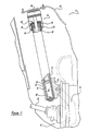
- FIG. 1 a MacPherson type suspension strut which incorporates the unique air spring / shock absorber interface in accordance with the present invention and which is designated generally by the reference numeral 10.
- Strut 10 comprises an outer reservoir tube 12 supported at its lower end in a cup-like mounting bracket 14.
- Mounting bracket 14 is attached to a steering knuckle 16 of a steerable front road wheel assembly 18 driven by a rotatable shaft 20.
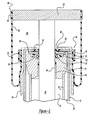
- a hydraulic shock absorber having a valved piston 22 mounted for reciprocating sliding movement in a pressure tube 24 radially spaced inwardly from reservoir tube 12 to provide a reservoir 26 for hydraulic damping fluid of strut 10.
- a base valve 28 provides for the controlled hydraulic communication between reservoir 26 and a lower working chamber 30 formed by piston 22 and pressure tube 24.
- Piston 22 is connected to the lower end of a cylindrical piston rod 32 which extends axially and upwardly through an upper working chamber 34 and a rod guide assembly 36.
- Rod guide assembly 36 comprises a rod guide 38, a bushing 40 and a rod seal assembly 42.
- Rod guide 38 is secured to both reservoir tube 12 and pressure tube 24.
- Bushing 40 is disposed within a central bore 44 in rod guide 38 through which piston rod 32 extends.
- Seal assembly 42 comprises an annular disc 46, a wiper seal 48, piston rod seal 50, a one-way seal 52 and a static seal 54.
- Wiper seal 48 is positioned towards the upper end of piston rod 32 and it operates to wipe dirt and residue from rod 32 as it moves in and out of rod guide assembly 36.
- Piston rod seal 50 rides against piston rod 32 and it serves to seal the oil and pressurized gas within reservoir 26 and upper working chamber 34.
- Seal 52 is positioned between rod guide 38 and annular disc 46.
- Seal 52 allows oil and gas which has migrated to a chamber 56 between seal assembly 42 and rod guide 38 to return to reservoir 26 through a passage 58 extending through rod guide 38. While seal 52 allows movement of gas from chamber 56 to reservoir 26, flow of gas in the opposite direction is prohibited by the design of seal 52.
- Seal 54 provides an oil seal and a gas seal between chamber 26 and the outside environment.
- Annular disc 46 is received within a pocket machined into rod guide 38. Preferably, seals 48, 50, 52 and 54 are all bonded to annular disc 46. Annular disc 46 can be manufactured from metal or plastic.
- An air spring assembly 60 is located between reservoir tube 12 and an upper mounting system 62.
- Upper mounting system 62 is secured to a sheet metal tower 64 formed in the wheel well of the vehicle body.
- Air spring assembly 60 includes a top cover 70 which is secured to or is a part of upper mounting system 62.
- An air sleeve 72 is sealingly attached at one end to top cover 70 by a clamping ring 74.
- the opposite end of air sleeve 72 is secured to an air spring piston 76 by a clamping ring 78.
- Air spring piston 76 is secured to reservoir tube 12 by the use of a press fit relationship between the outside diameter of reservoir tube 12 and the inside diameter of piston 76.
- Air spring assembly 60 defines a sealed chamber 80 which receives pressurized air in order to support the weight of the sprung mass of the vehicle.
- the present invention provides an elastomeric seal 82 which is disposed between air spring piston 76 and annular disc 46 of seal assembly 42.
- Elastomeric seal 82 can be a loose component, it can be bonded to air spring piston 76 or preferably it can be bonded to annular disc 46.
- Seal 82 is designed such that during the assembly of piston 76 to reservoir tube 12, seal 82 is compressed or preloaded. Seal 82 provides a gas seal between chamber 80 and the outside environment.
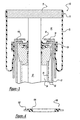
- Strut 110 is the same as strut 10 except that elastomeric seal 82 has been replaced with seal assembly 180.
- Seal assembly 180 comprises an annular metal plate 182 and an elastomeric seal 184 preferably manufactured from volcanized rubber which is bonded to plate 182.
- Plate 182 is designed to mate with piston 76 to position seal 184 between air spring piston 76 and reservoir tube 12 as shown in Figure 3 .
- Seal 184 is compressed and preloaded in the same manner as described above for seal 82 and seal 184 provides the same sealing as described above from seal 82.
- a MacPherson strut assembly 210 is illustrated.
- Strut 210 is the same as strut 10 except that reservoir tube 12 has been replaced with reservoir tube 212 and air spring assembly 60 has been replaced with air spring assembly 260.
- Reservoir tube 212 is the same as reservoir tube 12 with the exception that reservoir tube 212 defines and outwardly extending deformation 214 which supports air spring assembly 260. Reservoir tube 212 can also be referred to as outer tube 212.
- the suspension strut assembly 210 comprises a pressure tube 24 which is radially spaced inwardly from the outer tube 212 to provide a reservoir 26 for hydraulic damping fluid.
- the strut assembly 210 further includes a rod guide assembly 36, said rod guide assembly 36 comprising a rod guide 38, a bushing 40 and a rod seal assembly 42. The rod guide 38 is secured to the outer tube 212 and the pressure tube 24.
- Air spring assembly 260 includes top cover 70 which is secured to or a part of upper mounting system 62. Air sleeve 72 is sealingly attached at one end to top cover 70 by clamping ring 74. The opposite end of air sleeve 72 is secured to an air spring piston 276 by a clamping ring 278. Air spring piston 276 is secured to reservoir tube 212 by the use of a press fit relationship between the outside diameter of reservoir tube 212 and the inside diameter of piston 276. Outwardly extending deformation 214 forms a seat for piston 276 prohibiting further displacement of piston 276 along tube 212. Air spring assembly 260 defines a sealed chamber 280 which receives pressurized air in order to support the weight of the sprung mass of the vehicle.
- the air spring piston 276 comprises a first annular wall, which is in press-fit relation with the outer tube 212, an outwardly extending flange extending generally perpendicular to said first annular wall, and a second annular wall extending generally perpendicular to said flange.
- the elastomeric seal 282 engages said flange, said second annular wall and the outer tube 212 of the shock absorber.
- the air piston 276 includes a third annular wall generally parallel to said second annular wall, said air sleeve 72 extending between said third annular wall and said top cover 70. It is visible that the second annular wall is larger in diameter than said first annular wall and that the third annular wall is larger in diameter than the second annular wall.
- the air spring piston 276 includes an annular wall extending between said second and third annular walls.
- the present invention provides an elastomeric O-ring or seal 282 for sealing said chamber 280 which is disposed between the air spring piston 276 and the reservoir tube 212, more particularly between an outer surface of said reservoir tube 212 and an inner surface of said air spring piston 276.
- O-ring or seal 282 provides a gas seal between chamber 280 and the outside environment.
- O-ring or seal 282 can be bonded to the air spring piston 276.
Landscapes
- Engineering & Computer Science (AREA)
- Mechanical Engineering (AREA)
- Fluid-Damping Devices (AREA)
- Vehicle Body Suspensions (AREA)
Applications Claiming Priority (2)
| Application Number | Priority Date | Filing Date | Title |
|---|---|---|---|
| US09/867,297 US6443436B1 (en) | 2001-05-29 | 2001-05-29 | Air spring assembly on shock absorber with combined seal |
| EP02011389A EP1262341B1 (fr) | 2001-05-29 | 2002-05-24 | Ensemble ressort pneumatique monté sur un amortisseur en utilisant un joint d'étanchéité |
Related Parent Applications (1)
| Application Number | Title | Priority Date | Filing Date |
|---|---|---|---|
| EP02011389.0 Division | 2002-05-24 |
Publications (2)
| Publication Number | Publication Date |
|---|---|
| EP2272693A2 true EP2272693A2 (fr) | 2011-01-12 |
| EP2272693A3 EP2272693A3 (fr) | 2011-11-23 |
Family
ID=25349509
Family Applications (2)
| Application Number | Title | Priority Date | Filing Date |
|---|---|---|---|
| EP10177648A Withdrawn EP2272693A3 (fr) | 2001-05-29 | 2002-05-24 | Ensemble ressort pneumatique monté sur un amortisseur en utilisant un joint d'étanchéité |
| EP02011389A Expired - Lifetime EP1262341B1 (fr) | 2001-05-29 | 2002-05-24 | Ensemble ressort pneumatique monté sur un amortisseur en utilisant un joint d'étanchéité |
Family Applications After (1)
| Application Number | Title | Priority Date | Filing Date |
|---|---|---|---|
| EP02011389A Expired - Lifetime EP1262341B1 (fr) | 2001-05-29 | 2002-05-24 | Ensemble ressort pneumatique monté sur un amortisseur en utilisant un joint d'étanchéité |
Country Status (3)
| Country | Link |
|---|---|
| US (1) | US6443436B1 (fr) |
| EP (2) | EP2272693A3 (fr) |
| BR (1) | BR0201972B1 (fr) |
Cited By (2)
| Publication number | Priority date | Publication date | Assignee | Title |
|---|---|---|---|---|
| WO2017215855A1 (fr) * | 2016-06-16 | 2017-12-21 | Zf Friedrichshafen Ag | Dispositif de protection contre la corrosion pour un ensemble amortisseur de vibrations d'un véhicule automobile ainsi qu'ensemble amortisseur de vibrations comprenant le dispositif de protection contre la corrosion |
| DE102013203396C5 (de) | 2013-02-28 | 2021-08-05 | Ford Global Technologies, Llc | Rollbalg-Luftfeder |
Families Citing this family (32)
| Publication number | Priority date | Publication date | Assignee | Title |
|---|---|---|---|---|
| DE102004031873B3 (de) * | 2004-04-22 | 2005-11-17 | Zf Friedrichshafen Ag | Abrollrohr für einen Luftfederrollbalg |
| JP2006234083A (ja) * | 2005-02-25 | 2006-09-07 | Kayaba Ind Co Ltd | 単筒型油圧緩衝器 |
| US20060231361A1 (en) * | 2005-02-25 | 2006-10-19 | Shigeru Kojima | Single-cylinder hydraulic shock absorber |
| DE102005012072A1 (de) * | 2005-03-16 | 2006-09-28 | Volkswagen Ag | Kolbenführung |
| US7175165B1 (en) * | 2005-05-10 | 2007-02-13 | Link Mfg., Ltd. | Air spring and shock absorber assembly for use in suspension systems |
| DE102005060332B3 (de) * | 2005-12-16 | 2007-02-15 | Zf Friedrichshafen Ag | Luftfederbein |
| DE602006017871D1 (de) * | 2006-07-07 | 2010-12-09 | Freudenberg Carl Kg | Dichtungsvorrichtung |
| US20080143027A1 (en) * | 2006-12-14 | 2008-06-19 | Tenneco Automotive Operating Company Inc. | Top cap crimping for air spring suspension |
| US7954792B2 (en) * | 2008-02-22 | 2011-06-07 | Axletech International IP Holdings, LLC. | Strut assembly with air spring |
| DE102010037096A1 (de) * | 2010-08-20 | 2012-02-23 | Continental Teves Ag & Co. Ohg | Luftfederbein mit elastischer Kolbenlagerung |
| DE102012108930B3 (de) | 2012-09-21 | 2014-03-13 | Knorr-Bremse Systeme für Nutzfahrzeuge GmbH | Dichtungsanordnung für ein Luftfedersystem |
| US10300760B1 (en) | 2015-03-18 | 2019-05-28 | Apple Inc. | Fully-actuated suspension system |
| US9676240B2 (en) * | 2015-04-13 | 2017-06-13 | Reyco Granning, Llc | IFS including control arm and strut supported by steering knuckle load arm |
| DE102016224463A1 (de) * | 2016-12-08 | 2018-06-14 | Zf Friedrichshafen Ag | Luftfedermodul mit einem Stoßdämpfer |
| US10814690B1 (en) | 2017-04-18 | 2020-10-27 | Apple Inc. | Active suspension system with energy storage device |
| CN110997362B (zh) | 2017-05-08 | 2023-07-28 | 苹果公司 | 主动悬架系统 |
| US10899340B1 (en) | 2017-06-21 | 2021-01-26 | Apple Inc. | Vehicle with automated subsystems |
| US11173766B1 (en) | 2017-09-07 | 2021-11-16 | Apple Inc. | Suspension system with locking structure |
| US11065931B1 (en) | 2017-09-15 | 2021-07-20 | Apple Inc. | Active suspension system |
| US11124035B1 (en) | 2017-09-25 | 2021-09-21 | Apple Inc. | Multi-stage active suspension actuator |
| US10960723B1 (en) | 2017-09-26 | 2021-03-30 | Apple Inc. | Wheel-mounted suspension actuators |
| US11285773B1 (en) | 2018-09-12 | 2022-03-29 | Apple Inc. | Control system |
| US11634167B1 (en) | 2018-09-14 | 2023-04-25 | Apple Inc. | Transmitting axial and rotational movement to a hub |
| US11345209B1 (en) | 2019-06-03 | 2022-05-31 | Apple Inc. | Suspension systems |
| US11179991B1 (en) | 2019-09-23 | 2021-11-23 | Apple Inc. | Suspension systems |
| US11938922B1 (en) | 2019-09-23 | 2024-03-26 | Apple Inc. | Motion control system |
| US11707961B1 (en) | 2020-04-28 | 2023-07-25 | Apple Inc. | Actuator with reinforcing structure for torsion resistance |
| US11828339B1 (en) | 2020-07-07 | 2023-11-28 | Apple Inc. | Vibration control system |
| WO2022067388A1 (fr) * | 2020-09-30 | 2022-04-07 | The Dynamic Engineering Solution Pty Ltd | Ressort pneumatique pour un véhicule |
| CN117396339A (zh) | 2021-06-07 | 2024-01-12 | 苹果公司 | 质量阻尼器系统 |
| US12251973B2 (en) | 2022-06-10 | 2025-03-18 | Apple Inc. | Vibration absorber |
| US12168375B1 (en) | 2023-01-26 | 2024-12-17 | Apple Inc. | Motion control system |
Citations (1)
| Publication number | Priority date | Publication date | Assignee | Title |
|---|---|---|---|---|
| US4555096A (en) | 1980-11-20 | 1985-11-26 | Ford Motor Company | Pneumatic spring and strut assembly |
Family Cites Families (71)
| Publication number | Priority date | Publication date | Assignee | Title |
|---|---|---|---|---|
| US2122406A (en) | 1937-03-15 | 1938-07-05 | Houde Eng Corp | Hydraulic shock absorber |
| US2973953A (en) | 1957-01-02 | 1961-03-07 | Tyman H Fikse | Air spring assembly |
| US3088556A (en) | 1957-12-09 | 1963-05-07 | Bourcier Christian Marie Louis | Shock absorbers |
| US3000624A (en) | 1958-11-10 | 1961-09-19 | Gen Motors Corp | Air spring assembly and control device therefor |
| GB881114A (en) | 1959-08-28 | 1961-11-01 | Dewandre Co Ltd C | Improvements in or relating to air suspension systems for vehicles |
| US3078965A (en) | 1959-11-18 | 1963-02-26 | Bourcier Carbon Previnquieres | Shock absorbers |
| US3046000A (en) | 1960-01-15 | 1962-07-24 | Gen Motors Corp | Vehicle suspension spring assembly |
| US3046001A (en) | 1960-02-04 | 1962-07-24 | Gen Motors Corp | Combination shock absorber and air spring |
| US3042392A (en) | 1960-02-04 | 1962-07-03 | Gen Motors Corp | Combination shock absorber and air spring |
| US3063701A (en) | 1960-08-30 | 1962-11-13 | Gen Motors Corp | Shock absorber with air booster spring |
| US3063702A (en) | 1960-08-30 | 1962-11-13 | Gen Motors Corp | Combined shock absorber and air spring unit assembly |
| US3104119A (en) | 1960-09-12 | 1963-09-17 | Gen Motors Corp | Vehicle suspension system |
| US3178167A (en) | 1961-12-30 | 1965-04-13 | Bosch Gmbh Robert | Suspension for vehicles or the like |
| BE631369A (fr) | 1962-04-26 | 1900-01-01 | ||
| GB1027155A (en) | 1962-09-28 | 1966-04-27 | Girling Ltd | Improvements in suspension units for vehicles |
| US3149829A (en) | 1962-11-16 | 1964-09-22 | Maremont Corp | Self-damping suspension unit |
| US3149830A (en) | 1962-11-16 | 1964-09-22 | Maremont Corp | Self-damping suspension unit |
| US3235221A (en) | 1964-06-12 | 1966-02-15 | Flexible Air Seat Corp | Pneumatic cushioning seat support with variable cushioning and snubbing diaphragm action |
| US3385590A (en) | 1965-02-05 | 1968-05-28 | Girling Ltd | Vehicle suspension assemblies |
| USRE27883E (en) | 1966-02-23 | 1974-01-15 | Suspension system for vehicles | |
| DE1775090A1 (de) | 1967-07-11 | 1972-04-13 | Piero Montanari | Teleskopartiger hydropneumatischer Stossdaempfer |
| US3527451A (en) | 1968-05-13 | 1970-09-08 | Gen Motors Corp | Shock absorber with pressurizable reservoir chamber |
| US3700225A (en) | 1970-05-28 | 1972-10-24 | Monroe Belgium Nv | Combination shock absorber and supplementary air spring unit and method of assembling same |
| US3804217A (en) * | 1972-03-13 | 1974-04-16 | Monroe Belgium Nv | Pressurized shock absorber |
| US3954256A (en) | 1974-08-30 | 1976-05-04 | Monroe Belgium N. V. | Suspension system for automotive vehicles and the like |
| US3954257A (en) | 1974-08-30 | 1976-05-04 | Monroe Belgium N. V. | Suspension strut |
| US3954255A (en) | 1974-08-30 | 1976-05-04 | Monroe Belgium N. V. | Suspension strut |
| JPS5818543B2 (ja) | 1975-05-23 | 1983-04-13 | トキコ株式会社 | カンシヨウキニオケル ゲンスイリヨクハツセイソウチ |
| CA1058643A (fr) | 1976-03-22 | 1979-07-17 | Dale A. Palmer | Amortisseur |
| JPS6018878B2 (ja) | 1976-06-19 | 1985-05-13 | トキコ株式会社 | 緩衝器のガス封入方法 |
| HU174666B (hu) | 1977-06-30 | 1980-03-28 | Autoipari Kutato Intezet | Amortizator s vozdushnoj pruzhinoj i teleskopicheskim gasitelem kolebanij k avtomashinam dlja amortizacii kolebanij v zavisimosti ot nagruzki |
| JPS6035810Y2 (ja) * | 1979-11-20 | 1985-10-24 | トキコ株式会社 | 懸架装置 |
| DE3004307C2 (de) | 1980-02-06 | 1984-06-07 | Boge Gmbh, 5208 Eitorf | Selbstpumpendes hydropneumatisches Teleskop-Feder-Dämpferelement mit innerer Niveauregelung |
| US4392638A (en) | 1981-04-09 | 1983-07-12 | Tokico Ltd. | Vehicle suspension device |
| DE3122626A1 (de) | 1981-06-06 | 1983-01-20 | Fichtel & Sachs Ag, 8720 Schweinfurt | Fuellung von schwingungsdaempfern |
| DE3128723A1 (de) * | 1981-07-21 | 1983-02-10 | Fichtel & Sachs Ag, 8720 Schweinfurt | Hydropneumatischer zweirohr-schwingungsdaempfer oder federbeineinsatz mit einer verschlusskappe fuer ein behaelterrohr |
| US4574450A (en) | 1981-11-24 | 1986-03-11 | General Motors Corporation | Method of servicing a vehicle suspension unit with replacement air spring |
| US4534545A (en) | 1981-11-24 | 1985-08-13 | General Motors Corporation | Vehicle suspension unit with replacement air spring |
| US4588171A (en) * | 1981-12-18 | 1986-05-13 | Applied Power Inc. | Shock absorber and air spring assembly |
| DE3206124A1 (de) * | 1982-02-20 | 1983-09-01 | Fichtel & Sachs Ag, 8720 Schweinfurt | Hydropneumatischer zweirohr-schwingungsdaempfer mit einem im bereich einer kolbenstangenfuehrung angeordneten oelabstreifring |
| DE3324648A1 (de) | 1983-07-08 | 1985-01-17 | Fichtel & Sachs Ag, 8720 Schweinfurt | Schmierung von einander beruehrenden flaechen |
| US4629170A (en) | 1984-06-29 | 1986-12-16 | The Goodyear Tire & Rubber Company | Dual chamber air spring |
| US4648623A (en) * | 1986-02-28 | 1987-03-10 | General Motors Corporation | Vehicle suspension strut with lower rotary bearing cup assembly for a dirigible road wheel |
| US4802657A (en) | 1986-06-23 | 1989-02-07 | Monroe Auto Equipment Company | Vehicle leveling shock absorber assembly |
| US5009401A (en) | 1986-07-14 | 1991-04-23 | Bridgestone/Firestone, Inc. | Air spring suspension system with dual path isolation |
| US4712776A (en) | 1986-07-14 | 1987-12-15 | The Firestone Tire & Rubber Company | Air spring suspension system |
| US4989701A (en) | 1988-02-22 | 1991-02-05 | Atsugi Motor Parts Company Ltd | Shock absorber |
| US4826204A (en) | 1988-06-20 | 1989-05-02 | General Motors Corporation | Laterally offset dual volume air damper suspension strut with minimized side load |
| DE8813045U1 (de) * | 1988-10-17 | 1988-12-29 | Fichtel & Sachs Ag, 97424 Schweinfurt | Luftfeder |
| JPH02253026A (ja) * | 1989-03-27 | 1990-10-11 | Mazda Motor Corp | 車両のストラットマウント構造 |
| JPH02134338U (fr) * | 1989-04-13 | 1990-11-07 | ||
| DE4101065A1 (de) * | 1991-01-16 | 1992-07-23 | Bilstein August Gmbh Co Kg | Niveaugeregeltes federbein, insbesondere fuer kraftfahrzeuge |
| US5180144A (en) * | 1991-09-03 | 1993-01-19 | General Motors Corporation | Air spring module for a damper |
| DE9305390U1 (de) | 1993-04-08 | 1993-06-17 | MAN Nutzfahrzeuge AG, 8000 München | Luftfeder mit Rollbalg und integriertem Stoßdämpfer |
| US5649691A (en) | 1993-11-03 | 1997-07-22 | Fichtel & Sachs Ag | Shock absorber and pneumatic spring assembly |
| ES2122828B1 (es) | 1993-11-03 | 1999-07-01 | Fichtel & Sachs Ag | Resorte neumatico |
| US5607035A (en) * | 1994-10-13 | 1997-03-04 | Delphi France Automotive Systems | Hydraulic damper |
| GB9323047D0 (en) * | 1993-11-09 | 1994-01-05 | Acg France | A method of forming a suspension strut |
| GB9404343D0 (en) | 1994-03-07 | 1994-04-20 | Acg France | Suspension strut |
| DE4415045C1 (de) * | 1994-04-29 | 1995-10-26 | Fichtel & Sachs Ag | Luftfeder |
| DE19505026C2 (de) | 1995-02-15 | 1996-12-12 | Fichtel & Sachs Ag | Selbstpumpende Luftfeder |
| DE19508980C2 (de) * | 1995-03-13 | 2000-06-15 | Daimler Chrysler Ag | Luftfederbein |
| DE19515643C1 (de) * | 1995-04-28 | 1996-11-07 | Fichtel & Sachs Ag | Federbein mit Aluminiumbehälter |
| DE19522459C1 (de) * | 1995-06-21 | 1996-10-02 | Fichtel & Sachs Ag | Abdichtung eines Abrollrohres bei einer Luftfeder |
| DE19755549C2 (de) * | 1997-04-25 | 2001-09-27 | Mannesmann Sachs Ag | Federbein für Fahrzeuge |
| DE19819642A1 (de) * | 1997-05-28 | 1998-12-03 | Phoenix Ag | Luftfedersystem |
| DE19802703A1 (de) * | 1998-01-24 | 1999-07-29 | Bayerische Motoren Werke Ag | Luftfeder mit einem Rollbalg |
| DE19829362A1 (de) * | 1998-07-01 | 2000-01-13 | Bayerische Motoren Werke Ag | Abstützeinrichtung für ein Verbindungsteil und Verfahren zur Herstellung der Abstützeinrichtung |
| DE19834092C2 (de) * | 1998-07-29 | 2003-04-30 | Continental Ag | Luftfederbein und Verfahren zur Herstellung eines Luftfederbeins |
| DE19903553C2 (de) * | 1999-01-29 | 2001-03-08 | Daimler Chrysler Ag | Luftfederbein |
| US6202972B1 (en) * | 1999-04-26 | 2001-03-20 | Gabriel Ride Control Products, Inc. | Combination air spring and shock absorber |
-
2001
- 2001-05-29 US US09/867,297 patent/US6443436B1/en not_active Expired - Lifetime
-
2002
- 2002-05-24 EP EP10177648A patent/EP2272693A3/fr not_active Withdrawn
- 2002-05-24 EP EP02011389A patent/EP1262341B1/fr not_active Expired - Lifetime
- 2002-05-28 BR BRPI0201972-8A patent/BR0201972B1/pt not_active IP Right Cessation
Patent Citations (1)
| Publication number | Priority date | Publication date | Assignee | Title |
|---|---|---|---|---|
| US4555096A (en) | 1980-11-20 | 1985-11-26 | Ford Motor Company | Pneumatic spring and strut assembly |
Cited By (2)
| Publication number | Priority date | Publication date | Assignee | Title |
|---|---|---|---|---|
| DE102013203396C5 (de) | 2013-02-28 | 2021-08-05 | Ford Global Technologies, Llc | Rollbalg-Luftfeder |
| WO2017215855A1 (fr) * | 2016-06-16 | 2017-12-21 | Zf Friedrichshafen Ag | Dispositif de protection contre la corrosion pour un ensemble amortisseur de vibrations d'un véhicule automobile ainsi qu'ensemble amortisseur de vibrations comprenant le dispositif de protection contre la corrosion |
Also Published As
| Publication number | Publication date |
|---|---|
| EP2272693A3 (fr) | 2011-11-23 |
| BR0201972A (pt) | 2003-04-22 |
| US6443436B1 (en) | 2002-09-03 |
| EP1262341A2 (fr) | 2002-12-04 |
| EP1262341B1 (fr) | 2011-11-02 |
| BR0201972B1 (pt) | 2012-09-04 |
| EP1262341A3 (fr) | 2006-06-07 |
Similar Documents
| Publication | Publication Date | Title |
|---|---|---|
| US6443436B1 (en) | Air spring assembly on shock absorber with combined seal | |
| US4655438A (en) | Hydraulically damped dual sleeve air spring suspension | |
| US5107970A (en) | High pressure sealing system and method | |
| US7226045B2 (en) | Vehicle suspension system | |
| US3804217A (en) | Pressurized shock absorber | |
| EP1664578B1 (fr) | Derivation dependant de la course | |
| US6776402B2 (en) | Liquid-encapsulated damper mount and hydraulic damper mounting structure in suspension of automobile | |
| JP4723524B2 (ja) | ショックアブソーバ | |
| US6896110B2 (en) | Temperature compensated dual acting slip | |
| EP0905408A2 (fr) | Amortisseur hydraulique | |
| JP4230568B2 (ja) | 油圧緩衝器のばねシート固定構造 | |
| GB2127110A (en) | Multi-purpose fluid seal for movement control dampers and the like | |
| US6843472B2 (en) | Upper shock mount isolator with integral air spring housing pivot bearing | |
| US5667041A (en) | Suspension strut with hydraulic stop | |
| US7073643B2 (en) | Compensated rod for a frequency dependent damper shock absorber | |
| US6412615B1 (en) | Hydraulic shock absorber for motor vehicles | |
| CN112539241A (zh) | 用于阻尼器的基座构件 | |
| JP2009507191A (ja) | ロッドガイドシール | |
| CN104736360A (zh) | 用于空气弹簧系统的密封装置 | |
| US6510930B2 (en) | Floating rod guide | |
| US3954256A (en) | Suspension system for automotive vehicles and the like | |
| CN112119239B (zh) | 具有可调阻尼阀的振动阻尼器 | |
| US6962330B2 (en) | Vibration damper | |
| US20240375472A1 (en) | Damper oil seal cap with seal protection feature | |
| US20030178268A1 (en) | Suspension damper mounting ring casting with steel insert |
Legal Events
| Date | Code | Title | Description |
|---|---|---|---|
| PUAI | Public reference made under article 153(3) epc to a published international application that has entered the european phase |
Free format text: ORIGINAL CODE: 0009012 |
|
| AC | Divisional application: reference to earlier application |
Ref document number: 1262341 Country of ref document: EP Kind code of ref document: P |
|
| AK | Designated contracting states |
Kind code of ref document: A2 Designated state(s): DE FR GB |
|
| PUAL | Search report despatched |
Free format text: ORIGINAL CODE: 0009013 |
|
| AK | Designated contracting states |
Kind code of ref document: A3 Designated state(s): DE FR GB |
|
| RIC1 | Information provided on ipc code assigned before grant |
Ipc: F16F 9/084 20060101ALI20111017BHEP Ipc: B60G 15/12 20060101AFI20111017BHEP Ipc: F16F 9/36 20060101ALI20111017BHEP Ipc: B60G 11/28 20060101ALI20111017BHEP |
|
| STAA | Information on the status of an ep patent application or granted ep patent |
Free format text: STATUS: THE APPLICATION IS DEEMED TO BE WITHDRAWN |
|
| 18D | Application deemed to be withdrawn |
Effective date: 20120524 |