EP2273030A2 - Unité coulissante - Google Patents
Unité coulissante Download PDFInfo
- Publication number
- EP2273030A2 EP2273030A2 EP20100006952 EP10006952A EP2273030A2 EP 2273030 A2 EP2273030 A2 EP 2273030A2 EP 20100006952 EP20100006952 EP 20100006952 EP 10006952 A EP10006952 A EP 10006952A EP 2273030 A2 EP2273030 A2 EP 2273030A2
- Authority
- EP
- European Patent Office
- Prior art keywords
- frame
- sealing
- window
- lip
- sliding
- Prior art date
- Legal status (The legal status is an assumption and is not a legal conclusion. Google has not performed a legal analysis and makes no representation as to the accuracy of the status listed.)
- Withdrawn
Links
- 238000007789 sealing Methods 0.000 claims description 62
- 238000009413 insulation Methods 0.000 claims description 9
- 239000007788 liquid Substances 0.000 claims description 8
- 238000006073 displacement reaction Methods 0.000 claims description 5
- XLYOFNOQVPJJNP-UHFFFAOYSA-N water Substances O XLYOFNOQVPJJNP-UHFFFAOYSA-N 0.000 claims description 5
- 239000006261 foam material Substances 0.000 claims description 3
- 238000009833 condensation Methods 0.000 claims description 2
- 230000005494 condensation Effects 0.000 claims description 2
- 230000000694 effects Effects 0.000 description 4
- 229920001971 elastomer Polymers 0.000 description 4
- 239000000806 elastomer Substances 0.000 description 4
- XAGFODPZIPBFFR-UHFFFAOYSA-N aluminium Chemical compound [Al] XAGFODPZIPBFFR-UHFFFAOYSA-N 0.000 description 3
- 229910052782 aluminium Inorganic materials 0.000 description 3
- 238000004140 cleaning Methods 0.000 description 3
- 239000006260 foam Substances 0.000 description 3
- 238000009434 installation Methods 0.000 description 3
- 238000010276 construction Methods 0.000 description 2
- 230000005540 biological transmission Effects 0.000 description 1
- 230000015572 biosynthetic process Effects 0.000 description 1
- 239000012459 cleaning agent Substances 0.000 description 1
- 230000001419 dependent effect Effects 0.000 description 1
- 230000006866 deterioration Effects 0.000 description 1
- 238000001125 extrusion Methods 0.000 description 1
- 230000002349 favourable effect Effects 0.000 description 1
- 238000012423 maintenance Methods 0.000 description 1
- 238000004519 manufacturing process Methods 0.000 description 1
- 239000000463 material Substances 0.000 description 1
- 230000000149 penetrating effect Effects 0.000 description 1
- 229930194120 perseal Natural products 0.000 description 1
- 230000002028 premature Effects 0.000 description 1
- 230000002265 prevention Effects 0.000 description 1
- 239000005871 repellent Substances 0.000 description 1
- 230000002441 reversible effect Effects 0.000 description 1
- 238000010079 rubber tapping Methods 0.000 description 1
- 230000001360 synchronised effect Effects 0.000 description 1
- 230000007704 transition Effects 0.000 description 1
Images



Classifications
-
- E—FIXED CONSTRUCTIONS
- E04—BUILDING
- E04D—ROOF COVERINGS; SKY-LIGHTS; GUTTERS; ROOF-WORKING TOOLS
- E04D13/00—Special arrangements or devices in connection with roof coverings; Protection against birds; Roof drainage ; Sky-lights
- E04D13/03—Sky-lights; Domes; Ventilating sky-lights
- E04D13/035—Sky-lights; Domes; Ventilating sky-lights characterised by having movable parts
- E04D13/0358—Sky-lights; Domes; Ventilating sky-lights characterised by having movable parts the parts moving, in their own plane, e.g. rolling or sliding, or moving in parallel planes with or without an additional movement, e.g. both pivoting and rolling or sliding
-
- E—FIXED CONSTRUCTIONS
- E06—DOORS, WINDOWS, SHUTTERS, OR ROLLER BLINDS IN GENERAL; LADDERS
- E06B—FIXED OR MOVABLE CLOSURES FOR OPENINGS IN BUILDINGS, VEHICLES, FENCES OR LIKE ENCLOSURES IN GENERAL, e.g. DOORS, WINDOWS, BLINDS, GATES
- E06B7/00—Special arrangements or measures in connection with doors or windows
- E06B7/16—Sealing arrangements on wings or parts co-operating with the wings
- E06B7/22—Sealing arrangements on wings or parts co-operating with the wings by means of elastic edgings, e.g. elastic rubber tubes; by means of resilient edgings, e.g. felt or plush strips, resilient metal strips
- E06B7/23—Plastic, sponge rubber, or like strips or tubes
- E06B7/2305—Plastic, sponge rubber, or like strips or tubes with an integrally formed part for fixing the edging
-
- E—FIXED CONSTRUCTIONS
- E05—LOCKS; KEYS; WINDOW OR DOOR FITTINGS; SAFES
- E05D—HINGES OR SUSPENSION DEVICES FOR DOORS, WINDOWS OR WINGS
- E05D15/00—Suspension arrangements for wings
- E05D15/16—Suspension arrangements for wings for wings sliding vertically more or less in their own plane
- E05D15/165—Details, e.g. sliding or rolling guides
-
- E—FIXED CONSTRUCTIONS
- E05—LOCKS; KEYS; WINDOW OR DOOR FITTINGS; SAFES
- E05Y—INDEXING SCHEME ASSOCIATED WITH SUBCLASSES E05D AND E05F, RELATING TO CONSTRUCTION ELEMENTS, ELECTRIC CONTROL, POWER SUPPLY, POWER SIGNAL OR TRANSMISSION, USER INTERFACES, MOUNTING OR COUPLING, DETAILS, ACCESSORIES, AUXILIARY OPERATIONS NOT OTHERWISE PROVIDED FOR, APPLICATION THEREOF
- E05Y2800/00—Details, accessories and auxiliary operations not otherwise provided for
- E05Y2800/10—Additional functions
- E05Y2800/12—Sealing
-
- E—FIXED CONSTRUCTIONS
- E05—LOCKS; KEYS; WINDOW OR DOOR FITTINGS; SAFES
- E05Y—INDEXING SCHEME ASSOCIATED WITH SUBCLASSES E05D AND E05F, RELATING TO CONSTRUCTION ELEMENTS, ELECTRIC CONTROL, POWER SUPPLY, POWER SIGNAL OR TRANSMISSION, USER INTERFACES, MOUNTING OR COUPLING, DETAILS, ACCESSORIES, AUXILIARY OPERATIONS NOT OTHERWISE PROVIDED FOR, APPLICATION THEREOF
- E05Y2900/00—Application of doors, windows, wings or fittings thereof
- E05Y2900/10—Application of doors, windows, wings or fittings thereof for buildings or parts thereof
- E05Y2900/13—Type of wing
- E05Y2900/132—Doors
Definitions
- the invention relates to a sliding unit - hereinafter also referred to as a sliding element -, in particular a door or window unit, with a an opening of an outer skin of a building at least partially surrounding frame and at least one movably held in the frame element, which covers between the opening Closed position and the opening at least partially releasing open position with a parallel to the building skin stretched movement component is displaced, according to the preamble of claim 1.
- sliding unit and sliding element are used equivalently hereinafter and denote a complete structural unit or segment of a building skin, for example in the roof or the facade, this unit comprising a displaceable element, for example a door or a window.
- This may for example be a sliding door or a roof element in a conservatory construction, or also a door, window or roof window clement, which is arranged in a not configured as a conservatory building section, for example, surrounded by masonry or a conventional roofing.
- the surrounding frame can be firmly connected to the environment, for example an external building skin.
- the displaceable element is hereinafter referred to partially as a window, but may also be a door, an escape hatch or the like and is not necessarily transparent
- the invention is based on the problem to improve a sliding unit of a building exterior skin to the effect that the best possible sealing between the displaceable element and the frame is made possible, even with a deviating from a vertical mounting orientation of the sliding unit.
- a sliding unit is provided in the embodiment according to claim 1, which forms a good seal against ingress of liquid and a good heat seal over a located between the at least two seal lines air cushion due to the at least two sealing lines - advantageous by the use of Lippceitichtungen or other water-impermeable sliding seals such as closed profile gaskets - compared to brush or foam seals is significantly improved and the fact that not only relative to the building outer skin outer and inner surfaces is sealed, but at least a sealing line for sealing side surfaces (faces) relative to the fixed frame is arranged, also any inclination of the Sliding unit, for example, as a roof window, without deterioration of the sealing properties allows.
- the thermal insulation is particularly good when there are at least three seal lines extended with components in the direction of movement.
- a first sealing line is advantageously arranged between a leg of the frame which engages over the outer surface of the displaceable element on the outside and the outer surface of the displaceable element.
- This sealing line is in any case unaffected by the weight of the displaceable element and can substantially keep the externally applied liquid (rain, snow, cleaning agent ...) away from the intermediate region between the frame and the displaceable element.
- this first sealing line comprises a profile or lip seal, the at least one lip or rubber-elastic deformable profile with a longitudinal component in the direction of movement and especially in a lip seal with a transverse component transverse to the direction of movement on the displaceable element or on the frame, wherein the transverse component has an orientation pointing in the direction of the transverse center of the displaceable element orientation.
- the at least one sealing surface associated with the side surface comprises a lip seal whose at least one lip bears with a longitudinal component in the direction of movement and with a transverse component transverse to the direction of movement on the displaceable element or on the frame, wherein the transverse component in the direction of the outer surface of the displaceable Element-oriented orientation, here is a receiving channel is formed, which can dissipate from above incident water in an oblique orientation down.
- the combination of at least one sealing line on the side surface and a sealing line on the outer surface provides double security and also good thermal protection against escape of warm air from the inside.
- the distance between the frame and the displaceable element at least largely bridging heat insulation strips, such as a foam material, are arranged.
- an upwardly open drive frame may be provided, the drive elements, such as a spindle and drive motors, absorbs and may be derived as the last security possibly penetrating water down.
- a good seal for optically elegant slide elements is achieved, which are provided an approximately C-shaped, an opening-releasing frame and with a window which can be pushed out through the opening.
- Windows according to the invention can be made very large in area and, for example, have a window area of several square meters, the arrangement of the sealing line nevertheless providing good moisture and thermal insulation.
- the sliding unit has a window which has a thermally separated window frame and a thermally insulating filling held therein.
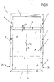
- the sliding unit shown in the drawing is designated overall by 1 and is also referred to below as a sliding element. It is arranged in an outer building skin and has laterally projecting flange portions 30 for connection to this outer skin.
- the sliding unit 1 can thus be arranged in an opening of the outer skin and form, for example, a vertical or oblique window or a door or escape hatch.
- a sliding unit obliquely in the roof of a conservatory or even within an otherwise designed building roof, z. B. surrounded by a conventional roofing, are arranged.
- the sliding unit 1 has an opening at least partially surrounding the frame 2, which is defined on the flange 30 on the surrounding outer skin and therefore can itself also predominantly lie in the opening.
- the frame 2 is approximately C-shaped in plan view and comprises three mutually perpendicular sections 3, 4, namely an upper portion 3 and two mutually parallel, hereof with a component facing side legs 4, so that the frame 2 at its lower end here, the upper portion 3 opposite, an opening 5 leaves freely.
- the sliding unit 1 can also be configured as a laterally or upwardly opening window or as a laterally or upwardly opening door, so that then the opening of the frame would be laterally or in the upper region.
- the frame can also be closed circumferentially, in which case the frame length would be so large that a displacement path for a displaceable in the frame 2 held element 6 would be provided in the frame.
- the displaceably held element 6 is formed as a window and occurs during its displacement in the opening direction partially through the opening 5 to the outside and over the length of the side legs 4 also ( Fig. 1 ).
- the side legs 4 can be kept visually elegant so short that they end in alignment with the displaceable element 6 in its closed position.
- the displaceably mounted element 6 is therefore displaceable between a closed position covering the aperture and an open position which at least partially releases the aperture with a movement component 31 extending parallel to the frame plane. It may itself comprise a fanz or partially circumferential window frame 7 and a filling 8, for example a double or Drcifach glazing.
- the displaceable element 6 is formed as a flat and substantially cuboidal body and has in the installed position with respect to the building exterior skin away facing outer surface 35 and on both sides of this angled standing side surfaces 36.
- At least one sealing line 33, 34 (here two) is arranged to seal the side surface 36 with respect to the fixed frame 2.
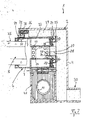
- the here two sealing line 33, 34 are arranged parallel to each other at a distance of a few to a few centimeters to seal the side surfaces 36 relative to the fixed frame 2. They are designed as lip sipes 24 and each have a more or less obliquely extending lip 25 and a fixed base portion 26.
- the lip 25 is flexibly deformable and rubber-elastic. By the contact with the frame 2, it enters a cross-section, for example, approximately L- or U-shaped angled relative to the base portion 26.
- the lip 25 is then sealing against the frame 2, wherein the comparatively long length of this lip 25 from the base portion up to their investment together with the material properties and the thin shape ensures that the lip 25 rests against the frame 2 with a relatively low contact pressure and yet a large sealing surface 37 is formed, for example, transverse to the lip 25 an extension of more than one centimeter.
- the lip 25 therefore causes only a slight sliding resistance in the relative movement between the displaceable element 6 and the frame 2, so that only a small amount of force is required for the displacement of the element 6 and no appreciable wear of the lip seal 24 takes place.
- sealing lines 32, 33, 34 are formed so that the associated elastomer profiles with its base portion 26 held on the displaceable element 6 and from there with a flexibly deformable lip 25 (several lips 25 are possible per seal line) to the frame 2. A reversal of these conditions would be possible.
- a first sealing lines 32 is moreover arranged between a leg 38 of the frame 2 which overlaps the outer surface 35 of the displaceable element 6 on the outside and the outer surface 35, in this case the frame 7, of the displaceable element 6.
- the lip 25 rests on the movable element 7 again in a considerable sealing width 37, wherein the conditions would again be reversible.
- sealing lines 32, 33, 34 are provided between the movable member 6 and the fixed frame 2 according to the drawing.
- Other sealing lines may be possible.
- the sealing lines 32, 33, 34 is also common that they have a similar orientation of the adjoining the frame 2 lip 25, namely the outer space facing, so that in each case by this orientation and the L-shaped configuration, a drain passage 39 is provided in the Liquid can drain within the frame 2. In the lower part of the sliding unit 1 can then be provided in the frame 2 associated drainage openings to the outside.
- the first seal line 32 comprises a lip seal 24 whose at least one lip 25 (two or more lips may be possible) with a longitudinal component in the direction of movement 31 and with a transverse component transverse to the direction of movement 31 on the displaceable Element 6 or rests against the frame 2, wherein the transverse component has a pointing in the direction of the transverse center 40 of the displaceable element 6 orientation, thus facing the outside, so that there initiated rain or condensation, snow, cleaning liquid or the like in the so can run through the seal 24 formed channel 39.
- the at least one sealing line 33, 34 associated with the side surfaces 36 each comprise such a lip seal 24, whose at least one lip 25 abuts the displaceable element 6 or the frame 2 with a longitudinal component in the direction of movement 31 and with a transverse component transverse to the direction of movement the transverse component has an orientation pointing in the direction of the outer surface 35 of the displaceable element, that is to say has an upwardly pointing component in the case of an inclined installation position.
- a drainage channel 39 is formed again in each seal line, so that about such water that has passed the first seal line 32, for example, when cleaning with a hose or even a Hoch horrrciniger, in the discharge channel 39 of the second 33 or at the latest the third seal line 34th collected and is derived obliquely down, without being able to penetrate into the interior.
- a spindle 11 receiving, upwardly open, here metallically formed C-profile 41 the frame 7 of the movable element 6 engages under and also can divert water to the outside and down.
- three sealing lines 32, 33, 34 are provided, of which a first sealing line 32 between the fixed frame 2 and the outer surface 35 of the movable member 6 and two further sealing lines 33, 34 parallel and spaced behind and / or one above the other - depending on the inclination of the installation position - between the frame 2 and the side surfaces 36 are arranged and the transverse components of the lips 25 of the latter sealing lines 33, 34 parallel to each other and the outer surface 35 are facing.
- a first sealing line 32 between the fixed frame 2 and the outer surface 35 of the movable member 6 and two further sealing lines 33, 34 parallel and spaced behind and / or one above the other - depending on the inclination of the installation position - between the frame 2 and the side surfaces 36 are arranged and the transverse components of the lips 25 of the latter sealing lines 33, 34 parallel to each other and the outer surface 35 are facing.
- air gaps build up between the sealing line 32, 33, 34, which further improve the thermal insulation.
- one or more thermally insulating strips 28, 29, for example of a water-repellent foam material, provided between the frame 2 and the movable element 6, for example glued, may be glued in each case between two sealing lines 32, 33 and 33, respectively , 34 at least largely bridge the distance between the frame 2 and the displaceable element 6, so as to prevent the formation of cold bridges. At the same time a friction during the movement of the element 6 to these strips 28, 29 is prevented by the remaining gap 27.
- the sealing lines 32, 33, 34 not only run in the side legs 4 of the outer frame 2, but are guided over the corner and continue in the upper section 3, so that there are the same good sealing and insulating properties are achieved. Down in the area of the opening 5 additional end caps are provided with insulation, for which there is enough space available, so that even there the insulation is not a problem.
- a plurality of windows (6) are arranged, of which at least one is designed as a movable window (6) in the manner described above and wherein at least two windows (6) are movable relative to each other.
- the window or the like element 6 to move this from its arranged in the frame 2 closed position in an out of the frame 2 through the opening 5 "down" outstanding open position, as well as the return movement motor.
- at least one electric motor is arranged within the frame 2, for example in the upper section 3. In this arrangement, a problem-free access to the motor is possible when the window 6 is open.
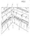
- On both sides of the electric motor one extends FIG. 2 apparent shaft 9, which transmits the rotational movement of the motor to an angle gear 10, of which in FIG. 2 only the case is visible.
- the angle gear 10 transmits the rotational movement of the shaft 9 on a spindle 11 which is mounted in the lateral portion (side legs) 4 of the frame 2, wherein also in the opposite lateral portion 4, such a spindle 11 is provided, which also by the same electric motor Shaft 9 and an angle gear 10 is driven. Also, the provision of two or even four synchronized drives, which are then each very small and can be arranged to save space in the frame 2, is possible. Due to the redundancy, the system can still be moved even if one motor fails or the remaining drives continue to move. This is particularly important for large moving elements 6, such as with edge lengths of two to three meters, important because they often can not be moved by their weight manually otherwise.
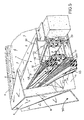
- FIG. 3 shows the spindle 11 and a located on the spindle 11 gate 12 with disassembled window 6.
- the window 6 is connected in use position with the gate 12, for example, releasably screwed, so that subsequently during a rotational movement of the spindle 11, the slide 12 in the one or the other direction 31, depending on the direction of rotation of the spindle 11, slides and accordingly the window 6 slides in the direction of its projecting through the opening 5 opening position or in the direction of its closed position.
- the backdrop 12 is composed of two link parts 14 and 15.
- a first link part 14 can be connected to the window 6, for example, be screwed, in the illustrated arrangement, this screw connection has not yet been made and the window 6 has not yet been mounted. Before or at the latest in the manufacture of the screw, possibly by self-tapping screws, internal threads are generated in this first link part 14.
- a dividing line 16 extends along the spindle, along which a second link part 15 adjoins the first link part 14.
- This second link member 15 is connected to the spindle 11 by a threaded through-hole and can only be removed axially from the spindle 11.
- Detachable fasteners 17 in the form of screws extend from the first link member 14 in the second link member 15 and connect these two.
- FIG. 5 shows a view obliquely from below into the frame construction of the slider element 1:
- a dimensionally stable lined with insulating foam and the side walls 36 of the movable member 6 opposite inner wall 18 is provided, wherein the frame 2 also has a lower portion 19 which below the opening 5, the two lateral sections 4 can connect to each other and can also be stiffened and insulated with insulating foam.
- the window frame 7 is along the two lateral sections 4 according to FIG. 5 purely movable (Not necessarily: a superimposed movement is possible), it being understood that the window frame 7 is thermally separated insofar as it has an upper and a lower aluminum profile 20, between which two plastic profiles 21 are located.
- Both aluminum profiles 20 each have a receiving channel 22 laterally for the elastomer profiles of, for example, lip seals 24, wherein each receiving channel 22 is bounded by two L-shaped support arms 23.
- the elastomer profiles described above for the lip seals 24 with their Basisabêten- 26 mechanically clamped and releasably held.
Landscapes
- Engineering & Computer Science (AREA)
- Civil Engineering (AREA)
- Structural Engineering (AREA)
- Architecture (AREA)
- Specific Sealing Or Ventilating Devices For Doors And Windows (AREA)
Applications Claiming Priority (2)
| Application Number | Priority Date | Filing Date | Title |
|---|---|---|---|
| DE202009005000U DE202009005000U1 (de) | 2009-07-07 | 2009-07-07 | Schiebeelement |
| DE202009004998U DE202009004998U1 (de) | 2009-07-07 | 2009-07-07 | Schiebeelement |
Publications (1)
| Publication Number | Publication Date |
|---|---|
| EP2273030A2 true EP2273030A2 (fr) | 2011-01-12 |
Family
ID=42830243
Family Applications (1)
| Application Number | Title | Priority Date | Filing Date |
|---|---|---|---|
| EP20100006952 Withdrawn EP2273030A2 (fr) | 2009-07-07 | 2010-07-06 | Unité coulissante |
Country Status (1)
| Country | Link |
|---|---|
| EP (1) | EP2273030A2 (fr) |
Cited By (1)
| Publication number | Priority date | Publication date | Assignee | Title |
|---|---|---|---|---|
| CN113006623A (zh) * | 2021-03-23 | 2021-06-22 | 北京金土豆科技服务有限公司 | 一种自动防护铝制窗 |
Citations (2)
| Publication number | Priority date | Publication date | Assignee | Title |
|---|---|---|---|---|
| DE4229661A1 (de) | 1992-09-04 | 1994-03-10 | Heinrich Kaml | Glasdach, insbesondere für Wintergärten |
| EP1126093B1 (fr) | 2000-02-16 | 2004-06-16 | Dietmar Naumann | Toit coulissant pour serre, toiture, lucarne ou similaire |
-
2010
- 2010-07-06 EP EP20100006952 patent/EP2273030A2/fr not_active Withdrawn
Patent Citations (2)
| Publication number | Priority date | Publication date | Assignee | Title |
|---|---|---|---|---|
| DE4229661A1 (de) | 1992-09-04 | 1994-03-10 | Heinrich Kaml | Glasdach, insbesondere für Wintergärten |
| EP1126093B1 (fr) | 2000-02-16 | 2004-06-16 | Dietmar Naumann | Toit coulissant pour serre, toiture, lucarne ou similaire |
Cited By (1)
| Publication number | Priority date | Publication date | Assignee | Title |
|---|---|---|---|---|
| CN113006623A (zh) * | 2021-03-23 | 2021-06-22 | 北京金土豆科技服务有限公司 | 一种自动防护铝制窗 |
Similar Documents
| Publication | Publication Date | Title |
|---|---|---|
| EP2957702B1 (fr) | Système de seuil de porte pour une porte d'entrée, porte de magasin ou similaire | |
| DE19846307C2 (de) | Lüftungseinrichtung | |
| EP3423658B1 (fr) | Porte, fenêtre ou élément de façade | |
| EP2136025B1 (fr) | Porte | |
| DE202010008921U1 (de) | Mitteldichtung für hoch wärmegedämmte Fenster oder Türen | |
| WO2016078961A1 (fr) | Dispositif d'étanchéité pour châssis mobile utilisé comme châssis coulissant ou châssis levant-coulissant mobile d'une fenêtre ou d'une porte | |
| EP2317054A2 (fr) | Porte coulissante | |
| EP4276268B1 (fr) | Portail sectionnel | |
| DE20105296U1 (de) | Lüftungsvorrichtung für Fenster, Türen, Fassadenelemente o.dgl. | |
| EP2072745A2 (fr) | Fenêtre dotée d'un dormant et d'un battant | |
| EP0784144A1 (fr) | Joint magnétique pour porte et profilés annexes pour sa fabrication | |
| DE102011001283B4 (de) | Türanordnung | |
| EP1147280B1 (fr) | Coque de facade pour batiment constituee de plaques pivotantes superposees ou disposees les unes derriere les autres | |
| EP2426306B1 (fr) | Unité coulissante | |
| DE3202508C2 (fr) | ||
| DE102018112434A1 (de) | Fenster | |
| DE102018112430A1 (de) | Fenster | |
| EP3299568B1 (fr) | Fenêtre de toit | |
| EP2439371B1 (fr) | Agencement constitué d'un agencement d'étanchéité et d'une fenêtre coulissante ou d'une porte coulissante | |
| EP2514905B1 (fr) | Cadre de fenêtre pour une fenêtre composite ou une porte-fenêtre composite | |
| DE19751657C2 (de) | Glaswand für Dachgeschoßräume unter einem geneigten Dach | |
| AT507406B1 (de) | Rahmenlose tür oder fenster, insbesondere schiebetür oder -fenster | |
| DE3628666A1 (de) | Profilleiste fuer rollaeden | |
| EP0978617A1 (fr) | Dispositif d'ouverture de fenêtre | |
| DE102005039397B3 (de) | Lamellenfenster |
Legal Events
| Date | Code | Title | Description |
|---|---|---|---|
| PUAI | Public reference made under article 153(3) epc to a published international application that has entered the european phase |
Free format text: ORIGINAL CODE: 0009012 |
|
| AK | Designated contracting states |
Kind code of ref document: A2 Designated state(s): AL AT BE BG CH CY CZ DE DK EE ES FI FR GB GR HR HU IE IS IT LI LT LU LV MC MK MT NL NO PL PT RO SE SI SK SM TR |
|
| AX | Request for extension of the european patent |
Extension state: BA ME RS |
|
| STAA | Information on the status of an ep patent application or granted ep patent |
Free format text: STATUS: THE APPLICATION IS DEEMED TO BE WITHDRAWN |
|
| 18D | Application deemed to be withdrawn |
Effective date: 20140201 |