EP2273079A1 - Dispositif post-traitement des gaz d'échappement - Google Patents
Dispositif post-traitement des gaz d'échappement Download PDFInfo
- Publication number
- EP2273079A1 EP2273079A1 EP10164309A EP10164309A EP2273079A1 EP 2273079 A1 EP2273079 A1 EP 2273079A1 EP 10164309 A EP10164309 A EP 10164309A EP 10164309 A EP10164309 A EP 10164309A EP 2273079 A1 EP2273079 A1 EP 2273079A1
- Authority
- EP
- European Patent Office
- Prior art keywords
- exhaust
- treatment device
- section
- particle filter
- insert
- Prior art date
- Legal status (The legal status is an assumption and is not a legal conclusion. Google has not performed a legal analysis and makes no representation as to the accuracy of the status listed.)
- Granted
Links
Images

Classifications
-
- F—MECHANICAL ENGINEERING; LIGHTING; HEATING; WEAPONS; BLASTING
- F01—MACHINES OR ENGINES IN GENERAL; ENGINE PLANTS IN GENERAL; STEAM ENGINES
- F01N—GAS-FLOW SILENCERS OR EXHAUST APPARATUS FOR MACHINES OR ENGINES IN GENERAL; GAS-FLOW SILENCERS OR EXHAUST APPARATUS FOR INTERNAL-COMBUSTION ENGINES
- F01N3/00—Exhaust or silencing apparatus having means for purifying, rendering innocuous, or otherwise treating exhaust
- F01N3/02—Exhaust or silencing apparatus having means for purifying, rendering innocuous, or otherwise treating exhaust for cooling, or for removing solid constituents of, exhaust
- F01N3/021—Exhaust or silencing apparatus having means for purifying, rendering innocuous, or otherwise treating exhaust for cooling, or for removing solid constituents of, exhaust by means of filters
- F01N3/033—Exhaust or silencing apparatus having means for purifying, rendering innocuous, or otherwise treating exhaust for cooling, or for removing solid constituents of, exhaust by means of filters in combination with other devices
- F01N3/035—Exhaust or silencing apparatus having means for purifying, rendering innocuous, or otherwise treating exhaust for cooling, or for removing solid constituents of, exhaust by means of filters in combination with other devices with catalytic reactors
-
- F—MECHANICAL ENGINEERING; LIGHTING; HEATING; WEAPONS; BLASTING
- F01—MACHINES OR ENGINES IN GENERAL; ENGINE PLANTS IN GENERAL; STEAM ENGINES
- F01N—GAS-FLOW SILENCERS OR EXHAUST APPARATUS FOR MACHINES OR ENGINES IN GENERAL; GAS-FLOW SILENCERS OR EXHAUST APPARATUS FOR INTERNAL-COMBUSTION ENGINES
- F01N13/00—Exhaust or silencing apparatus characterised by constructional features
- F01N13/009—Exhaust or silencing apparatus characterised by constructional features having two or more separate purifying devices arranged in series
- F01N13/0097—Exhaust or silencing apparatus characterised by constructional features having two or more separate purifying devices arranged in series the purifying devices are arranged in a single housing
-
- F—MECHANICAL ENGINEERING; LIGHTING; HEATING; WEAPONS; BLASTING
- F01—MACHINES OR ENGINES IN GENERAL; ENGINE PLANTS IN GENERAL; STEAM ENGINES
- F01N—GAS-FLOW SILENCERS OR EXHAUST APPARATUS FOR MACHINES OR ENGINES IN GENERAL; GAS-FLOW SILENCERS OR EXHAUST APPARATUS FOR INTERNAL-COMBUSTION ENGINES
- F01N3/00—Exhaust or silencing apparatus having means for purifying, rendering innocuous, or otherwise treating exhaust
- F01N3/02—Exhaust or silencing apparatus having means for purifying, rendering innocuous, or otherwise treating exhaust for cooling, or for removing solid constituents of, exhaust
- F01N3/021—Exhaust or silencing apparatus having means for purifying, rendering innocuous, or otherwise treating exhaust for cooling, or for removing solid constituents of, exhaust by means of filters
- F01N3/022—Exhaust or silencing apparatus having means for purifying, rendering innocuous, or otherwise treating exhaust for cooling, or for removing solid constituents of, exhaust by means of filters characterised by specially adapted filtering structure, e.g. honeycomb, mesh or fibrous
- F01N3/0222—Exhaust or silencing apparatus having means for purifying, rendering innocuous, or otherwise treating exhaust for cooling, or for removing solid constituents of, exhaust by means of filters characterised by specially adapted filtering structure, e.g. honeycomb, mesh or fibrous the structure being monolithic, e.g. honeycombs
-
- F—MECHANICAL ENGINEERING; LIGHTING; HEATING; WEAPONS; BLASTING
- F01—MACHINES OR ENGINES IN GENERAL; ENGINE PLANTS IN GENERAL; STEAM ENGINES
- F01N—GAS-FLOW SILENCERS OR EXHAUST APPARATUS FOR MACHINES OR ENGINES IN GENERAL; GAS-FLOW SILENCERS OR EXHAUST APPARATUS FOR INTERNAL-COMBUSTION ENGINES
- F01N3/00—Exhaust or silencing apparatus having means for purifying, rendering innocuous, or otherwise treating exhaust
- F01N3/02—Exhaust or silencing apparatus having means for purifying, rendering innocuous, or otherwise treating exhaust for cooling, or for removing solid constituents of, exhaust
- F01N3/021—Exhaust or silencing apparatus having means for purifying, rendering innocuous, or otherwise treating exhaust for cooling, or for removing solid constituents of, exhaust by means of filters
- F01N3/023—Exhaust or silencing apparatus having means for purifying, rendering innocuous, or otherwise treating exhaust for cooling, or for removing solid constituents of, exhaust by means of filters using means for regenerating the filters, e.g. by burning trapped particles
- F01N3/0231—Exhaust or silencing apparatus having means for purifying, rendering innocuous, or otherwise treating exhaust for cooling, or for removing solid constituents of, exhaust by means of filters using means for regenerating the filters, e.g. by burning trapped particles using special exhaust apparatus upstream of the filter for producing nitrogen dioxide, e.g. for continuous filter regeneration systems [CRT]
-
- F—MECHANICAL ENGINEERING; LIGHTING; HEATING; WEAPONS; BLASTING
- F01—MACHINES OR ENGINES IN GENERAL; ENGINE PLANTS IN GENERAL; STEAM ENGINES
- F01N—GAS-FLOW SILENCERS OR EXHAUST APPARATUS FOR MACHINES OR ENGINES IN GENERAL; GAS-FLOW SILENCERS OR EXHAUST APPARATUS FOR INTERNAL-COMBUSTION ENGINES
- F01N3/00—Exhaust or silencing apparatus having means for purifying, rendering innocuous, or otherwise treating exhaust
- F01N3/08—Exhaust or silencing apparatus having means for purifying, rendering innocuous, or otherwise treating exhaust for rendering innocuous
- F01N3/10—Exhaust or silencing apparatus having means for purifying, rendering innocuous, or otherwise treating exhaust for rendering innocuous by thermal or catalytic conversion of noxious components of exhaust
- F01N3/18—Exhaust or silencing apparatus having means for purifying, rendering innocuous, or otherwise treating exhaust for rendering innocuous by thermal or catalytic conversion of noxious components of exhaust characterised by methods of operation; Control
- F01N3/20—Exhaust or silencing apparatus having means for purifying, rendering innocuous, or otherwise treating exhaust for rendering innocuous by thermal or catalytic conversion of noxious components of exhaust characterised by methods of operation; Control specially adapted for catalytic conversion
- F01N3/206—Adding periodically or continuously substances to exhaust gases for promoting purification, e.g. catalytic material in liquid form, NOx reducing agents
- F01N3/2066—Selective catalytic reduction [SCR]
-
- F—MECHANICAL ENGINEERING; LIGHTING; HEATING; WEAPONS; BLASTING
- F01—MACHINES OR ENGINES IN GENERAL; ENGINE PLANTS IN GENERAL; STEAM ENGINES
- F01N—GAS-FLOW SILENCERS OR EXHAUST APPARATUS FOR MACHINES OR ENGINES IN GENERAL; GAS-FLOW SILENCERS OR EXHAUST APPARATUS FOR INTERNAL-COMBUSTION ENGINES
- F01N2570/00—Exhaust treating apparatus eliminating, absorbing or adsorbing specific elements or compounds
- F01N2570/10—Carbon or carbon oxides
-
- F—MECHANICAL ENGINEERING; LIGHTING; HEATING; WEAPONS; BLASTING
- F01—MACHINES OR ENGINES IN GENERAL; ENGINE PLANTS IN GENERAL; STEAM ENGINES
- F01N—GAS-FLOW SILENCERS OR EXHAUST APPARATUS FOR MACHINES OR ENGINES IN GENERAL; GAS-FLOW SILENCERS OR EXHAUST APPARATUS FOR INTERNAL-COMBUSTION ENGINES
- F01N2570/00—Exhaust treating apparatus eliminating, absorbing or adsorbing specific elements or compounds
- F01N2570/14—Nitrogen oxides
-
- F—MECHANICAL ENGINEERING; LIGHTING; HEATING; WEAPONS; BLASTING
- F01—MACHINES OR ENGINES IN GENERAL; ENGINE PLANTS IN GENERAL; STEAM ENGINES
- F01N—GAS-FLOW SILENCERS OR EXHAUST APPARATUS FOR MACHINES OR ENGINES IN GENERAL; GAS-FLOW SILENCERS OR EXHAUST APPARATUS FOR INTERNAL-COMBUSTION ENGINES
- F01N2610/00—Adding substances to exhaust gases
- F01N2610/02—Adding substances to exhaust gases the substance being ammonia or urea
-
- Y—GENERAL TAGGING OF NEW TECHNOLOGICAL DEVELOPMENTS; GENERAL TAGGING OF CROSS-SECTIONAL TECHNOLOGIES SPANNING OVER SEVERAL SECTIONS OF THE IPC; TECHNICAL SUBJECTS COVERED BY FORMER USPC CROSS-REFERENCE ART COLLECTIONS [XRACs] AND DIGESTS
- Y02—TECHNOLOGIES OR APPLICATIONS FOR MITIGATION OR ADAPTATION AGAINST CLIMATE CHANGE
- Y02A—TECHNOLOGIES FOR ADAPTATION TO CLIMATE CHANGE
- Y02A50/00—TECHNOLOGIES FOR ADAPTATION TO CLIMATE CHANGE in human health protection, e.g. against extreme weather
- Y02A50/20—Air quality improvement or preservation, e.g. vehicle emission control or emission reduction by using catalytic converters
-
- Y—GENERAL TAGGING OF NEW TECHNOLOGICAL DEVELOPMENTS; GENERAL TAGGING OF CROSS-SECTIONAL TECHNOLOGIES SPANNING OVER SEVERAL SECTIONS OF THE IPC; TECHNICAL SUBJECTS COVERED BY FORMER USPC CROSS-REFERENCE ART COLLECTIONS [XRACs] AND DIGESTS
- Y02—TECHNOLOGIES OR APPLICATIONS FOR MITIGATION OR ADAPTATION AGAINST CLIMATE CHANGE
- Y02T—CLIMATE CHANGE MITIGATION TECHNOLOGIES RELATED TO TRANSPORTATION
- Y02T10/00—Road transport of goods or passengers
- Y02T10/10—Internal combustion engine [ICE] based vehicles
- Y02T10/12—Improving ICE efficiencies
Definitions
- the present invention relates to an exhaust aftertreatment device for an exhaust system of an internal combustion engine, in particular of a motor vehicle.
- Exhaust after-treatment devices are usually constructed by juxtaposing components with different functionalities.
- an oxidation catalyst, a particle filter, an addition device with an optional mixer, optionally a hydrolysis catalyst, a selective catalytic reduction catalyst (SCR catalyst) and a blocking catalyst can be installed successively.
- unburned hydrocarbons, hydrogen and carbon monoxide are reacted with oxygen to carbon dioxide and water by the oxidation catalyst to largely free the exhaust gas stream of unburned hydrocarbons and carbon monoxide.
- the particulate filter filters out any soot particles from the exhaust gas flow as well as fine dusts from the exhaust gas.
- this particulate filter is repeatedly heated by heating so far that the soot particles retained by the particulate filter can react with oxygen to form carbon dioxide.
- a urea-water solution is optionally mixed with exhaust gas in the optional mixer, in which case the water is evaporated simultaneously and a fluid containing ultrafine urea or ammonia, is formed.
- a hydrolysis catalyst for the hydrolysis of urea in ammonia and CO 2 can be used.
- the ammonia is again required to convert any nitrogen oxides formed on the SCR catalyst during combustion of the fuel in the internal combustion engine into nitrogen and water by selective catalytic reduction (SCR) with ammonia.
- SCR selective catalytic reduction
- At the end of this series of catalysts is usually a barrier catalyst installed, which oxidizes excess ammonia residues from the exhaust gas stream to nitrogen, nitrogen oxides and water, so that almost no ammonia residues are released through the exhaust gas to the environment.
- the present invention addresses the problem of providing for an exhaust after-treatment device an improved or at least another embodiment, which is characterized in particular by a smaller footprint, a low complexity and a smaller number of components.
- the invention is based on the general idea of providing an insert having a plurality of parallel flow passages, at least partially provided in an inflow-side first section with an oxidation catalyst coating forming at least one oxidation catalyst, and a downstream second section as a particle filter with inlet channels closed on the outflow side and downstream forming the first section closed outlet channels. Furthermore, optionally at least one addition device for a reducing agent can be provided.
- An advantage of this design is the reduced space requirement achieved by the integration of particle filter and oxidation catalyst and the reduction of the complexity of the exhaust aftertreatment device.
- the exhaust aftertreatment device may be provided with lateral recesses into which the addition device may introduce the reducing agent or a reducing agent-exhaust gas mixture.
- the lateral recesses are formed as a bore or cutout. This integrative design also results in a smaller footprint and a smaller heat radiating surface.
- the invention is based on the general idea to use in a exhaust aftertreatment device for an exhaust system of an internal combustion engine, in particular a motor vehicle, a particulate filter in which at least one particulate filter element has outflow closed inlet channels and outflow closed outlet channels, wherein at least some of the inlet channels and / or at least some of the outlet channels are at least partially provided with an SCR catalyst coating, forming at least one SCR catalyst.
- a particulate filter in which at least one particulate filter element has outflow closed inlet channels and outflow closed outlet channels, wherein at least some of the inlet channels and / or at least some of the outlet channels are at least partially provided with an SCR catalyst coating, forming at least one SCR catalyst.
- such an exhaust aftertreatment device may have at least one addition device for a reducing agent.
- An advantage of this design is the combination of a particulate filter with an SCR catalyst coating in assembly with at least one addition device. As a result, the space required and the complexity of such an exhaust aftertreatment device can be significantly reduced.
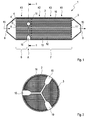
- Fig. 1 has an exhaust aftertreatment device 1, which can be used in an exhaust system of an internal combustion engine, in particular a motor vehicle, for use, arranged in a housing 2 insert 3.
- This insert 3 is equipped with a plurality of channel walls 4, 4 'surrounded and arranged in parallel channels 5, 5'.
- the insert 3 can be subdivided into an inflow-side, first section 6 and an outflow-side, second section 7.
- the flow direction of the exhaust gas is in Fig. 1 indicated by arrows 15.
- the housing 2 has an inflow opening 8 in the region of the first section 6 and an outflow opening 9 in the region of the second section 7.
- the exhaust aftertreatment device 1 is equipped with at least one recess 10 in the form of a bore.
- the channels 5, 5 ' are in the second section 7 mutually and with respect to the second section 7 end with plugs 11, 11' closed so that they form a plurality of inlet channels 12 and a plurality of outlet channels 13 depending on the arrangement of the plugs 11, 11 '.
- an inlet channel 12 is closed with a closure plug 11 oriented toward the outflow opening 9, while an outlet channel 13 in each case closes a closure plug 11 in the transition region from the first section 6 to the second section 7.
- an inlet channel 12 oriented to the inflow opening 8 is open and closed in the direction of the outflow opening 9 with a closure plug 11 ', while an outlet channel 13 is closed by a closure plug 11 in the transition region from the first section 6 to the second section 7 and oriented to the outflow opening 9 is open. Accordingly, an exhaust stream entering the exhaust aftertreatment device 1 through the inflow opening 8 will flow through the channels 5, 5 'until some of the channels 5, 5' have a plug 11 which prevents the flow of exhaust gas in these channels 5 from continuing.
- the exhaust gas flow is then in these channels 5 through the channel walls 4, 4 'in the channels 5' and penetrate to the plugs 11 'in the region of the outflow opening 9 through the inlet channels 12 to flow through the channel walls 4, 4' in the Outlet passages 13 to be pressed through.
- the exhaust gas flow finally leaves the outlet channels 13 in the direction of the outflow opening 9.
- an oxidation catalyst coating can be applied to the channel walls 4, 4 'of the channels 5, 5'.
- this oxidation catalyst coating at least one oxidation catalyst K1 is formed in the first section 6. Through this at least one oxidation catalyst K1, it is possible to reduce the content of unburned hydrocarbons and carbon monoxide in the exhaust gas by oxidation of these pollutants on the oxidation catalyst K1 with oxygen.
- recesses 10 are provided, through which a reducing agent can be introduced into the exhaust aftertreatment device 1 by means of an addition device 17 and / or mixing device 14.
- a reducing agent can be introduced into the exhaust aftertreatment device 1 by means of an addition device 17 and / or mixing device 14.
- injectors as a reducing agent z. B. a urea-water solution after z. B. specification of the operating point the internal combustion engine injected. But it can also be directly ammonia or z. B. fuel are injected into the recesses 10.
- z. B. Fuel is used in a corresponding catalytic coating of the corresponding channels, in particular the inlet channels, this for the regeneration of a arranged after the recesses 10 in the direction of the exhaust gas flow particle filter K3.
- the particle filter K3 is heated to such an extent by exothermic reaction of the fuel with oxygen on the adapted coating that the particle filter K3 can regenerate by reacting the soot particles with oxygen.
- the reduced space also finds a very good mixing z.
- the urea-water solution by injection on the hot insert 3 instead.
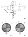
- the mixing by a plurality of interconnected recesses, as in Fig. 2 shown to be supported.
- the reducing agent such as. As a urea-water solution, are mixed with branched off from the exhaust gas exhaust gas and z. B. after the evaporation of the water of the urea-water solution through the recesses 10, 10 ', 10 "are pressed into the insert 3.
- FIG. 5 is a diagrammatic representation of recesses 10, 10 ', 10 "in the form of a bore 10, as in Fig. 2 shown, but also spatially in the direction of the exhaust stream subsequent, alternately arranged and in its entirety the cross-section of the insert 3 completely covering cutouts 10 ', 10 "according to Fig. 4 respectively.
- FIG. 5 is a diagrammatic representation of recesses 10, 10 ', 10 "in the form of a bore 10, as in Fig. 2 shown, but also spatially in the direction of the exhaust stream subsequent, alternately arranged and in its entirety the cross-section of the insert 3 completely covering cutouts 10 ', 10 "according to Fig. 4 respectively.
- such recesses 10 ', 10 may also be formed in a form other than a quarter circle, be distributed over more than two planes B, C and, furthermore, also be formed overlapping each other.
- Such circular or arcuate incisions are particularly easy to manufacture, since they can be produced, for example, with a disc milling machine or a grinding wheel.
- a later break of these webs 18,18 'and thus a disintegration of the insert 3 into two parts does not affect the function and durability of the exhaust aftertreatment device 1.
- marginal webs 18, 18 'and / or webs 18' can form within the insert 3.
- the channel walls 4, 4 'in the inlet channels 12 are provided with an SCR catalyst coating.
- This SCR catalyst coating forms at least one SCR catalyst K2.
- This can cause the nitrogen oxides occurring in the exhaust gas stream to react with the reducing agent introduced into the recesses 10, 10 ', 10 "in such a way that the nitrogen oxides be reduced.
- this is accomplished with ammonia or a urea-water solution, wherein the ammonia reacts with the nitrogen oxides to nitrogen and water.
- the channel walls 4, 4' act as a particle filter K3, which retains soot particles and fine dust contained in the exhaust gas.
- the channel walls 4, 4 ' have a highly porous, lightweight base material, such. Cordierite, alumina, mulith or aluminum titanate. Due to the highly porous structure, the application of greater catalytic activity is made possible by larger washcoat amounts.
- a regeneration of the particulate filter K3 can also be facilitated by exothermic reactions of fuel or partial combustion products of the fuel with oxygen.
- the outlet channels 13 may in turn be equipped with a barrier catalyst coating, which ensures that the SCR catalyst K2 passing excess ammonia is oxidized by the blocking catalyst K4, so that the amount of ammonia in the exhaust gas can be reduced. However, if necessary, nitrogen oxides are formed by the blocking catalyst K4, for which reason the injected amount of ammonia should be metered precisely.
- the exhaust aftertreatment device 1 only an insert 3.
- This insert 3 may consist of several parts, but is preferably formed in one piece or in one piece and in particular constructed of a ceramic and / or metallic monoliths.
- an oxidation catalyst K1, an SCR catalyst K2, a particulate filter K3 and a trap catalyst K4 are integrally formed with each other and
- Such an insert can also have at least one recess 10, 10 ', 10 "for receiving an addition device 17 or mixing device 14.
- Such a one-piece insert 3 preferably has a first section 6 designed as an oxidation catalytic converter K1 and a second section 7 designed as an SCR catalytic converter K2, a particle filter K3 and a blocking catalytic converter K4.
- Both sections 6, 7 are preferably formed integrally or monolithically with each other.
- the two sections 6, 7 can each also be individually monolithically shaped and fastened to one another.
- the use is easier to produce and, on the other hand, one can dispense with the formations 10, 10 ', 10 "which are difficult to represent and weaken the use in its stability.
- the insert 3 by means of only one storage device 16, z. B. in the form of a bearing mat, stored in only one housing 2.
- the one-piece insert 3 is flowed through in a Abgaströmungslegi 15 by the exhaust gas without the exhaust gas must be deflected in the housing in order to be directed to the next catalyst component can.
- the catalyst components can be arranged axially one behind the other in a tubular housing 2.
- the plugs 11, which close the outlet channels 13 on the inflow side, are axially spaced from the inflow opening 17 of the insert 3.
Landscapes
- Engineering & Computer Science (AREA)
- Chemical & Material Sciences (AREA)
- Combustion & Propulsion (AREA)
- Mechanical Engineering (AREA)
- General Engineering & Computer Science (AREA)
- Chemical Kinetics & Catalysis (AREA)
- Health & Medical Sciences (AREA)
- Toxicology (AREA)
- Exhaust Gas After Treatment (AREA)
Applications Claiming Priority (1)
| Application Number | Priority Date | Filing Date | Title |
|---|---|---|---|
| DE102009024535A DE102009024535A1 (de) | 2009-06-10 | 2009-06-10 | Abgasnachbehandlungsvorrichtung |
Publications (2)
| Publication Number | Publication Date |
|---|---|
| EP2273079A1 true EP2273079A1 (fr) | 2011-01-12 |
| EP2273079B1 EP2273079B1 (fr) | 2012-08-22 |
Family
ID=42547609
Family Applications (1)
| Application Number | Title | Priority Date | Filing Date |
|---|---|---|---|
| EP10164309A Not-in-force EP2273079B1 (fr) | 2009-06-10 | 2010-05-28 | Dispositif post-traitement des gaz d'échappement |
Country Status (3)
| Country | Link |
|---|---|
| US (1) | US8454897B2 (fr) |
| EP (1) | EP2273079B1 (fr) |
| DE (1) | DE102009024535A1 (fr) |
Cited By (3)
| Publication number | Priority date | Publication date | Assignee | Title |
|---|---|---|---|---|
| WO2012143139A1 (fr) * | 2011-04-21 | 2012-10-26 | Deutz Aktiengesellschaft | Filtre à particules pourvu d'un revêtement catalytique |
| DE102011050788A1 (de) | 2011-06-01 | 2012-12-06 | Ford Global Technologies, Llc. | Abgasnachbehandlungsvorrichtung und -verfahren für einen Ottomotor |
| EP2865858B1 (fr) * | 2013-10-24 | 2019-05-15 | Bosal Emission Control Systems NV | Système et procédé pour le traitement de gaz d'échappement |
Families Citing this family (3)
| Publication number | Priority date | Publication date | Assignee | Title |
|---|---|---|---|---|
| BR112017026777B1 (pt) | 2015-06-12 | 2022-11-16 | Donaldson Company, Inc | Dispositivo de tratamento de escape |
| EP3997314B1 (fr) | 2019-07-11 | 2024-03-06 | Donaldson Company, Inc. | Arrangement d'un conduit de dosage pour un système de post-traitement des gaz d'échappement |
| EP3792462A1 (fr) | 2019-09-13 | 2021-03-17 | Donaldson Company, Inc. | Ensembles de dosage et de mélange pour système de post-traitement d'échappement |
Citations (7)
| Publication number | Priority date | Publication date | Assignee | Title |
|---|---|---|---|---|
| WO2001096717A1 (fr) * | 2000-06-16 | 2001-12-20 | Johnson Matthey Public Limited Company | Reacteur destine a traiter des gaz d'echappement |
| EP1348843A2 (fr) * | 2002-03-29 | 2003-10-01 | Hitachi Metals, Ltd. | Filtre en nid d'abeilles en céramique et procédé d'épuration de gaz d'échappement |
| EP1371826A2 (fr) * | 2002-06-13 | 2003-12-17 | Toyota Jidosha Kabushiki Kaisha | Filtre catalytique pour la purification des gaz d'échappement |
| EP1752629A1 (fr) * | 2004-06-02 | 2007-02-14 | Hino Motors, Ltd. | Filtre de matières particulaires |
| EP1892394A1 (fr) * | 2006-08-16 | 2008-02-27 | MAN Nutzfahrzeuge AG | Système de traitement postérieur de gaz d'échappement |
| DE102006051790A1 (de) * | 2006-11-03 | 2008-05-08 | Daimler Ag | Abgasnachbehandlungssystem eines Verbrennungsmotors |
| US20080132405A1 (en) * | 2003-08-05 | 2008-06-05 | Joseph Allan Patchett | Catalyzed SCR Filter and Emission Treatment System |
Family Cites Families (5)
| Publication number | Priority date | Publication date | Assignee | Title |
|---|---|---|---|---|
| ATE79158T1 (de) * | 1985-03-05 | 1992-08-15 | Brehk Ventures | Verfahren und vorrichtung zum filtern von festen teilchen aus einem dieselmotorauspuff. |
| US6001314A (en) * | 1997-09-15 | 1999-12-14 | General Motors Corporation | Catalytic converter housing with deep drawn shells |
| GB9919013D0 (en) * | 1999-08-13 | 1999-10-13 | Johnson Matthey Plc | Reactor |
| JP2006272157A (ja) * | 2005-03-29 | 2006-10-12 | Hitachi Metals Ltd | セラミックハニカムフィルタ及び排気ガス浄化装置 |
| AT504391B1 (de) * | 2006-11-13 | 2008-12-15 | Pankl Emission Control Systems | Kombiniertes abgasreinigungssystem |
-
2009
- 2009-06-10 DE DE102009024535A patent/DE102009024535A1/de not_active Withdrawn
-
2010
- 2010-05-28 EP EP10164309A patent/EP2273079B1/fr not_active Not-in-force
- 2010-06-09 US US12/797,129 patent/US8454897B2/en not_active Expired - Fee Related
Patent Citations (7)
| Publication number | Priority date | Publication date | Assignee | Title |
|---|---|---|---|---|
| WO2001096717A1 (fr) * | 2000-06-16 | 2001-12-20 | Johnson Matthey Public Limited Company | Reacteur destine a traiter des gaz d'echappement |
| EP1348843A2 (fr) * | 2002-03-29 | 2003-10-01 | Hitachi Metals, Ltd. | Filtre en nid d'abeilles en céramique et procédé d'épuration de gaz d'échappement |
| EP1371826A2 (fr) * | 2002-06-13 | 2003-12-17 | Toyota Jidosha Kabushiki Kaisha | Filtre catalytique pour la purification des gaz d'échappement |
| US20080132405A1 (en) * | 2003-08-05 | 2008-06-05 | Joseph Allan Patchett | Catalyzed SCR Filter and Emission Treatment System |
| EP1752629A1 (fr) * | 2004-06-02 | 2007-02-14 | Hino Motors, Ltd. | Filtre de matières particulaires |
| EP1892394A1 (fr) * | 2006-08-16 | 2008-02-27 | MAN Nutzfahrzeuge AG | Système de traitement postérieur de gaz d'échappement |
| DE102006051790A1 (de) * | 2006-11-03 | 2008-05-08 | Daimler Ag | Abgasnachbehandlungssystem eines Verbrennungsmotors |
Cited By (4)
| Publication number | Priority date | Publication date | Assignee | Title |
|---|---|---|---|---|
| WO2012143139A1 (fr) * | 2011-04-21 | 2012-10-26 | Deutz Aktiengesellschaft | Filtre à particules pourvu d'un revêtement catalytique |
| DE102011050788A1 (de) | 2011-06-01 | 2012-12-06 | Ford Global Technologies, Llc. | Abgasnachbehandlungsvorrichtung und -verfahren für einen Ottomotor |
| US9238982B2 (en) | 2011-06-01 | 2016-01-19 | Ford Global Technologies, Llc | Exhaust gas aftertreatment device and method for a gasoline engine |
| EP2865858B1 (fr) * | 2013-10-24 | 2019-05-15 | Bosal Emission Control Systems NV | Système et procédé pour le traitement de gaz d'échappement |
Also Published As
| Publication number | Publication date |
|---|---|
| US20100316537A1 (en) | 2010-12-16 |
| EP2273079B1 (fr) | 2012-08-22 |
| DE102009024535A1 (de) | 2010-12-16 |
| US8454897B2 (en) | 2013-06-04 |
Similar Documents
| Publication | Publication Date | Title |
|---|---|---|
| EP2813679B1 (fr) | Système d'échappement d'un moteur à combustion interne | |
| EP1830042B1 (fr) | Mélangeur statique et dispositif de traitement de gaz d'échappement | |
| EP2266681B1 (fr) | Installation de gaz d'échappement dotée d'une amenée de moyen de réduction et d'un élément de filtre avec un catalyseur SCR | |
| EP2101049B1 (fr) | Système de post-traitement de gaz d'échappement compact | |
| EP2598730B1 (fr) | Appareil de traitement des gaz d'échappement | |
| EP2574750B1 (fr) | Dispositif de mélange et/ou d'évaporation | |
| DE602004005899T2 (de) | Abgassystem mit partikelfilter für einen magermotor | |
| DE102020124106A1 (de) | Kraftfahrzeugabgasnachbehandlungssystem | |
| EP2273079B1 (fr) | Dispositif post-traitement des gaz d'échappement | |
| DE112009001055T5 (de) | Abgaselement, ein statisches Mittel zum Beimischen eines Zusatzes zu Abgasen umfassend | |
| WO2012131042A1 (fr) | Unité de traitement de gaz d'échappement compacte comprenant une zone de mélange et procédé pour mélanger des gaz d'échappement | |
| EP2985434A1 (fr) | Dispositif de nettoyage de gaz d'échappement pour un véhicule, notamment pour un véhicule utilitaire | |
| DE102020127384A1 (de) | Probenentnahmevorrichtung für einen abgassensor | |
| WO2020260331A1 (fr) | Dispositif de post-traitement de gaz d'échappement | |
| EP2271417B1 (fr) | Filtre à particules à revêtement hydrolysant | |
| EP4382730B1 (fr) | Agencement de traitement de gaz d'échappement | |
| DE102011120221B4 (de) | Mischer für eine Abgasanlage und Abgasanlage | |
| EP1537303A1 (fr) | Systeme et procede de purification de gaz d'echappement | |
| DE102007036254A1 (de) | Abgasanlage einer Brennkraftmaschine | |
| DE102008022998A1 (de) | Vorrichtung und Verfahren zur Reinigung von Abgasen für einen Abgasstrang einer Brennkraftmaschine | |
| DE102005037959A1 (de) | Vorrichtung zur Nachbehandlung von Abgasen | |
| EP4382733A1 (fr) | Agencement de traitement de gaz d'échappement | |
| DE102011089850A1 (de) | Misch- und/oder Verdampfungseinrichtung für ein Abgassystem eines Kraftfahrzeugs | |
| DE102022131263A1 (de) | Katalysator eines Fahrzeuges | |
| DE102015226039A1 (de) | Partikelfilter für ein Abgasnachbehandlungssystem, Abgasnachbehandlungssystem und Verfahren zum Herstellen eines Partikelfilters |
Legal Events
| Date | Code | Title | Description |
|---|---|---|---|
| PUAI | Public reference made under article 153(3) epc to a published international application that has entered the european phase |
Free format text: ORIGINAL CODE: 0009012 |
|
| AK | Designated contracting states |
Kind code of ref document: A1 Designated state(s): AL AT BE BG CH CY CZ DE DK EE ES FI FR GB GR HR HU IE IS IT LI LT LU LV MC MK MT NL NO PL PT RO SE SI SK SM TR |
|
| AX | Request for extension of the european patent |
Extension state: BA ME RS |
|
| 17P | Request for examination filed |
Effective date: 20110712 |
|
| 17Q | First examination report despatched |
Effective date: 20110809 |
|
| RIC1 | Information provided on ipc code assigned before grant |
Ipc: F01N 3/023 20060101ALI20111219BHEP Ipc: F01N 3/20 20060101ALI20111219BHEP Ipc: F01N 3/022 20060101ALI20111219BHEP Ipc: F01N 3/035 20060101AFI20111219BHEP |
|
| GRAP | Despatch of communication of intention to grant a patent |
Free format text: ORIGINAL CODE: EPIDOSNIGR1 |
|
| GRAS | Grant fee paid |
Free format text: ORIGINAL CODE: EPIDOSNIGR3 |
|
| GRAA | (expected) grant |
Free format text: ORIGINAL CODE: 0009210 |
|
| AK | Designated contracting states |
Kind code of ref document: B1 Designated state(s): AL AT BE BG CH CY CZ DE DK EE ES FI FR GB GR HR HU IE IS IT LI LT LU LV MC MK MT NL NO PL PT RO SE SI SK SM TR |
|
| REG | Reference to a national code |
Ref country code: GB Ref legal event code: FG4D Free format text: NOT ENGLISH |
|
| REG | Reference to a national code |
Ref country code: CH Ref legal event code: EP |
|
| REG | Reference to a national code |
Ref country code: IE Ref legal event code: FG4D Free format text: LANGUAGE OF EP DOCUMENT: GERMAN |
|
| REG | Reference to a national code |
Ref country code: AT Ref legal event code: REF Ref document number: 572141 Country of ref document: AT Kind code of ref document: T Effective date: 20120915 |
|
| REG | Reference to a national code |
Ref country code: DE Ref legal event code: R096 Ref document number: 502010001133 Country of ref document: DE Effective date: 20121018 |
|
| REG | Reference to a national code |
Ref country code: NL Ref legal event code: VDEP Effective date: 20120822 |
|
| REG | Reference to a national code |
Ref country code: LT Ref legal event code: MG4D Effective date: 20120822 |
|
| PG25 | Lapsed in a contracting state [announced via postgrant information from national office to epo] |
Ref country code: FI Free format text: LAPSE BECAUSE OF FAILURE TO SUBMIT A TRANSLATION OF THE DESCRIPTION OR TO PAY THE FEE WITHIN THE PRESCRIBED TIME-LIMIT Effective date: 20120822 Ref country code: IS Free format text: LAPSE BECAUSE OF FAILURE TO SUBMIT A TRANSLATION OF THE DESCRIPTION OR TO PAY THE FEE WITHIN THE PRESCRIBED TIME-LIMIT Effective date: 20121222 Ref country code: HR Free format text: LAPSE BECAUSE OF FAILURE TO SUBMIT A TRANSLATION OF THE DESCRIPTION OR TO PAY THE FEE WITHIN THE PRESCRIBED TIME-LIMIT Effective date: 20120822 Ref country code: NO Free format text: LAPSE BECAUSE OF FAILURE TO SUBMIT A TRANSLATION OF THE DESCRIPTION OR TO PAY THE FEE WITHIN THE PRESCRIBED TIME-LIMIT Effective date: 20121122 Ref country code: LT Free format text: LAPSE BECAUSE OF FAILURE TO SUBMIT A TRANSLATION OF THE DESCRIPTION OR TO PAY THE FEE WITHIN THE PRESCRIBED TIME-LIMIT Effective date: 20120822 |
|
| PG25 | Lapsed in a contracting state [announced via postgrant information from national office to epo] |
Ref country code: LV Free format text: LAPSE BECAUSE OF FAILURE TO SUBMIT A TRANSLATION OF THE DESCRIPTION OR TO PAY THE FEE WITHIN THE PRESCRIBED TIME-LIMIT Effective date: 20120822 Ref country code: SE Free format text: LAPSE BECAUSE OF FAILURE TO SUBMIT A TRANSLATION OF THE DESCRIPTION OR TO PAY THE FEE WITHIN THE PRESCRIBED TIME-LIMIT Effective date: 20120822 Ref country code: SI Free format text: LAPSE BECAUSE OF FAILURE TO SUBMIT A TRANSLATION OF THE DESCRIPTION OR TO PAY THE FEE WITHIN THE PRESCRIBED TIME-LIMIT Effective date: 20120822 Ref country code: PT Free format text: LAPSE BECAUSE OF FAILURE TO SUBMIT A TRANSLATION OF THE DESCRIPTION OR TO PAY THE FEE WITHIN THE PRESCRIBED TIME-LIMIT Effective date: 20121224 Ref country code: GR Free format text: LAPSE BECAUSE OF FAILURE TO SUBMIT A TRANSLATION OF THE DESCRIPTION OR TO PAY THE FEE WITHIN THE PRESCRIBED TIME-LIMIT Effective date: 20121123 |
|
| PG25 | Lapsed in a contracting state [announced via postgrant information from national office to epo] |
Ref country code: NL Free format text: LAPSE BECAUSE OF FAILURE TO SUBMIT A TRANSLATION OF THE DESCRIPTION OR TO PAY THE FEE WITHIN THE PRESCRIBED TIME-LIMIT Effective date: 20120822 |
|
| PG25 | Lapsed in a contracting state [announced via postgrant information from national office to epo] |
Ref country code: DK Free format text: LAPSE BECAUSE OF FAILURE TO SUBMIT A TRANSLATION OF THE DESCRIPTION OR TO PAY THE FEE WITHIN THE PRESCRIBED TIME-LIMIT Effective date: 20120822 Ref country code: CZ Free format text: LAPSE BECAUSE OF FAILURE TO SUBMIT A TRANSLATION OF THE DESCRIPTION OR TO PAY THE FEE WITHIN THE PRESCRIBED TIME-LIMIT Effective date: 20120822 Ref country code: EE Free format text: LAPSE BECAUSE OF FAILURE TO SUBMIT A TRANSLATION OF THE DESCRIPTION OR TO PAY THE FEE WITHIN THE PRESCRIBED TIME-LIMIT Effective date: 20120822 Ref country code: RO Free format text: LAPSE BECAUSE OF FAILURE TO SUBMIT A TRANSLATION OF THE DESCRIPTION OR TO PAY THE FEE WITHIN THE PRESCRIBED TIME-LIMIT Effective date: 20120822 Ref country code: ES Free format text: LAPSE BECAUSE OF FAILURE TO SUBMIT A TRANSLATION OF THE DESCRIPTION OR TO PAY THE FEE WITHIN THE PRESCRIBED TIME-LIMIT Effective date: 20121203 |
|
| PG25 | Lapsed in a contracting state [announced via postgrant information from national office to epo] |
Ref country code: PL Free format text: LAPSE BECAUSE OF FAILURE TO SUBMIT A TRANSLATION OF THE DESCRIPTION OR TO PAY THE FEE WITHIN THE PRESCRIBED TIME-LIMIT Effective date: 20120822 Ref country code: SK Free format text: LAPSE BECAUSE OF FAILURE TO SUBMIT A TRANSLATION OF THE DESCRIPTION OR TO PAY THE FEE WITHIN THE PRESCRIBED TIME-LIMIT Effective date: 20120822 Ref country code: IT Free format text: LAPSE BECAUSE OF FAILURE TO SUBMIT A TRANSLATION OF THE DESCRIPTION OR TO PAY THE FEE WITHIN THE PRESCRIBED TIME-LIMIT Effective date: 20120822 |
|
| PLBE | No opposition filed within time limit |
Free format text: ORIGINAL CODE: 0009261 |
|
| STAA | Information on the status of an ep patent application or granted ep patent |
Free format text: STATUS: NO OPPOSITION FILED WITHIN TIME LIMIT |
|
| RAP2 | Party data changed (patent owner data changed or rights of a patent transferred) |
Owner name: EBERSPAECHER EXHAUST TECHNOLOGY GMBH & CO. KG |
|
| 26N | No opposition filed |
Effective date: 20130523 |
|
| PG25 | Lapsed in a contracting state [announced via postgrant information from national office to epo] |
Ref country code: BG Free format text: LAPSE BECAUSE OF FAILURE TO SUBMIT A TRANSLATION OF THE DESCRIPTION OR TO PAY THE FEE WITHIN THE PRESCRIBED TIME-LIMIT Effective date: 20121122 |
|
| REG | Reference to a national code |
Ref country code: DE Ref legal event code: R097 Ref document number: 502010001133 Country of ref document: DE Effective date: 20130523 |
|
| REG | Reference to a national code |
Ref country code: GB Ref legal event code: 732E Free format text: REGISTERED BETWEEN 20130905 AND 20130911 |
|
| PG25 | Lapsed in a contracting state [announced via postgrant information from national office to epo] |
Ref country code: CY Free format text: LAPSE BECAUSE OF FAILURE TO SUBMIT A TRANSLATION OF THE DESCRIPTION OR TO PAY THE FEE WITHIN THE PRESCRIBED TIME-LIMIT Effective date: 20120822 |
|
| BERE | Be: lapsed |
Owner name: J. EBERSPACHER G.M.B.H. & CO. KG Effective date: 20130531 |
|
| PG25 | Lapsed in a contracting state [announced via postgrant information from national office to epo] |
Ref country code: MC Free format text: LAPSE BECAUSE OF FAILURE TO SUBMIT A TRANSLATION OF THE DESCRIPTION OR TO PAY THE FEE WITHIN THE PRESCRIBED TIME-LIMIT Effective date: 20120822 |
|
| REG | Reference to a national code |
Ref country code: IE Ref legal event code: MM4A |
|
| PG25 | Lapsed in a contracting state [announced via postgrant information from national office to epo] |
Ref country code: BE Free format text: LAPSE BECAUSE OF NON-PAYMENT OF DUE FEES Effective date: 20130531 |
|
| PG25 | Lapsed in a contracting state [announced via postgrant information from national office to epo] |
Ref country code: IE Free format text: LAPSE BECAUSE OF NON-PAYMENT OF DUE FEES Effective date: 20130528 |
|
| REG | Reference to a national code |
Ref country code: CH Ref legal event code: PL |
|
| PG25 | Lapsed in a contracting state [announced via postgrant information from national office to epo] |
Ref country code: LI Free format text: LAPSE BECAUSE OF NON-PAYMENT OF DUE FEES Effective date: 20140531 Ref country code: CH Free format text: LAPSE BECAUSE OF NON-PAYMENT OF DUE FEES Effective date: 20140531 |
|
| PG25 | Lapsed in a contracting state [announced via postgrant information from national office to epo] |
Ref country code: MT Free format text: LAPSE BECAUSE OF FAILURE TO SUBMIT A TRANSLATION OF THE DESCRIPTION OR TO PAY THE FEE WITHIN THE PRESCRIBED TIME-LIMIT Effective date: 20120822 |
|
| PG25 | Lapsed in a contracting state [announced via postgrant information from national office to epo] |
Ref country code: SM Free format text: LAPSE BECAUSE OF FAILURE TO SUBMIT A TRANSLATION OF THE DESCRIPTION OR TO PAY THE FEE WITHIN THE PRESCRIBED TIME-LIMIT Effective date: 20120822 |
|
| PG25 | Lapsed in a contracting state [announced via postgrant information from national office to epo] |
Ref country code: TR Free format text: LAPSE BECAUSE OF FAILURE TO SUBMIT A TRANSLATION OF THE DESCRIPTION OR TO PAY THE FEE WITHIN THE PRESCRIBED TIME-LIMIT Effective date: 20120822 |
|
| PG25 | Lapsed in a contracting state [announced via postgrant information from national office to epo] |
Ref country code: MK Free format text: LAPSE BECAUSE OF FAILURE TO SUBMIT A TRANSLATION OF THE DESCRIPTION OR TO PAY THE FEE WITHIN THE PRESCRIBED TIME-LIMIT Effective date: 20120822 Ref country code: LU Free format text: LAPSE BECAUSE OF NON-PAYMENT OF DUE FEES Effective date: 20130528 Ref country code: HU Free format text: LAPSE BECAUSE OF FAILURE TO SUBMIT A TRANSLATION OF THE DESCRIPTION OR TO PAY THE FEE WITHIN THE PRESCRIBED TIME-LIMIT; INVALID AB INITIO Effective date: 20100528 |
|
| REG | Reference to a national code |
Ref country code: FR Ref legal event code: PLFP Year of fee payment: 7 |
|
| REG | Reference to a national code |
Ref country code: AT Ref legal event code: MM01 Ref document number: 572141 Country of ref document: AT Kind code of ref document: T Effective date: 20150528 |
|
| PG25 | Lapsed in a contracting state [announced via postgrant information from national office to epo] |
Ref country code: AT Free format text: LAPSE BECAUSE OF NON-PAYMENT OF DUE FEES Effective date: 20150528 |
|
| REG | Reference to a national code |
Ref country code: FR Ref legal event code: PLFP Year of fee payment: 8 |
|
| REG | Reference to a national code |
Ref country code: FR Ref legal event code: PLFP Year of fee payment: 9 |
|
| PG25 | Lapsed in a contracting state [announced via postgrant information from national office to epo] |
Ref country code: AL Free format text: LAPSE BECAUSE OF FAILURE TO SUBMIT A TRANSLATION OF THE DESCRIPTION OR TO PAY THE FEE WITHIN THE PRESCRIBED TIME-LIMIT Effective date: 20120822 |
|
| REG | Reference to a national code |
Ref country code: DE Ref legal event code: R081 Ref document number: 502010001133 Country of ref document: DE Owner name: PUREM GMBH, DE Free format text: FORMER OWNER: J. EBERSPAECHER GMBH & CO. KG, 73730 ESSLINGEN, DE |
|
| PGFP | Annual fee paid to national office [announced via postgrant information from national office to epo] |
Ref country code: FR Payment date: 20230517 Year of fee payment: 14 Ref country code: DE Payment date: 20230519 Year of fee payment: 14 |
|
| PGFP | Annual fee paid to national office [announced via postgrant information from national office to epo] |
Ref country code: GB Payment date: 20230522 Year of fee payment: 14 |
|
| REG | Reference to a national code |
Ref country code: DE Ref legal event code: R119 Ref document number: 502010001133 Country of ref document: DE |
|
| GBPC | Gb: european patent ceased through non-payment of renewal fee |
Effective date: 20240528 |
|
| PG25 | Lapsed in a contracting state [announced via postgrant information from national office to epo] |
Ref country code: DE Free format text: LAPSE BECAUSE OF NON-PAYMENT OF DUE FEES Effective date: 20241203 |
|
| PG25 | Lapsed in a contracting state [announced via postgrant information from national office to epo] |
Ref country code: FR Free format text: LAPSE BECAUSE OF NON-PAYMENT OF DUE FEES Effective date: 20240531 |
|
| PG25 | Lapsed in a contracting state [announced via postgrant information from national office to epo] |
Ref country code: GB Free format text: LAPSE BECAUSE OF NON-PAYMENT OF DUE FEES Effective date: 20240528 |