EP2273085A1 - System mit Stromgenerator und in Abgas einer Wärmekraftmaschine enthaltener Energierückgewinnungsturbine - Google Patents
System mit Stromgenerator und in Abgas einer Wärmekraftmaschine enthaltener Energierückgewinnungsturbine Download PDFInfo
- Publication number
- EP2273085A1 EP2273085A1 EP10168578A EP10168578A EP2273085A1 EP 2273085 A1 EP2273085 A1 EP 2273085A1 EP 10168578 A EP10168578 A EP 10168578A EP 10168578 A EP10168578 A EP 10168578A EP 2273085 A1 EP2273085 A1 EP 2273085A1
- Authority
- EP
- European Patent Office
- Prior art keywords
- turbine
- inlet
- turbines
- electric generator
- wheel
- Prior art date
- Legal status (The legal status is an assumption and is not a legal conclusion. Google has not performed a legal analysis and makes no representation as to the accuracy of the status listed.)
- Withdrawn
Links
Images

Classifications
-
- F—MECHANICAL ENGINEERING; LIGHTING; HEATING; WEAPONS; BLASTING
- F01—MACHINES OR ENGINES IN GENERAL; ENGINE PLANTS IN GENERAL; STEAM ENGINES
- F01N—GAS-FLOW SILENCERS OR EXHAUST APPARATUS FOR MACHINES OR ENGINES IN GENERAL; GAS-FLOW SILENCERS OR EXHAUST APPARATUS FOR INTERNAL-COMBUSTION ENGINES
- F01N5/00—Exhaust or silencing apparatus combined or associated with devices profiting by exhaust energy
- F01N5/04—Exhaust or silencing apparatus combined or associated with devices profiting by exhaust energy the devices using kinetic energy
-
- F—MECHANICAL ENGINEERING; LIGHTING; HEATING; WEAPONS; BLASTING
- F01—MACHINES OR ENGINES IN GENERAL; ENGINE PLANTS IN GENERAL; STEAM ENGINES
- F01D—NON-POSITIVE DISPLACEMENT MACHINES OR ENGINES, e.g. STEAM TURBINES
- F01D15/00—Adaptations of machines or engines for special use; Combinations of engines with devices driven thereby
- F01D15/10—Adaptations for driving, or combinations with, electric generators
-
- F—MECHANICAL ENGINEERING; LIGHTING; HEATING; WEAPONS; BLASTING
- F02—COMBUSTION ENGINES; HOT-GAS OR COMBUSTION-PRODUCT ENGINE PLANTS
- F02B—INTERNAL-COMBUSTION PISTON ENGINES; COMBUSTION ENGINES IN GENERAL
- F02B37/00—Engines characterised by provision of pumps driven at least for part of the time by exhaust
- F02B37/005—Exhaust driven pumps being combined with an exhaust driven auxiliary apparatus, e.g. a ventilator
-
- F—MECHANICAL ENGINEERING; LIGHTING; HEATING; WEAPONS; BLASTING
- F02—COMBUSTION ENGINES; HOT-GAS OR COMBUSTION-PRODUCT ENGINE PLANTS
- F02B—INTERNAL-COMBUSTION PISTON ENGINES; COMBUSTION ENGINES IN GENERAL
- F02B37/00—Engines characterised by provision of pumps driven at least for part of the time by exhaust
- F02B37/12—Control of the pumps
- F02B37/18—Control of the pumps by bypassing exhaust from the inlet to the outlet of turbine or to the atmosphere
-
- F—MECHANICAL ENGINEERING; LIGHTING; HEATING; WEAPONS; BLASTING
- F02—COMBUSTION ENGINES; HOT-GAS OR COMBUSTION-PRODUCT ENGINE PLANTS
- F02B—INTERNAL-COMBUSTION PISTON ENGINES; COMBUSTION ENGINES IN GENERAL
- F02B37/00—Engines characterised by provision of pumps driven at least for part of the time by exhaust
- F02B37/12—Control of the pumps
- F02B37/24—Control of the pumps by using pumps or turbines with adjustable guide vanes
-
- F—MECHANICAL ENGINEERING; LIGHTING; HEATING; WEAPONS; BLASTING
- F05—INDEXING SCHEMES RELATING TO ENGINES OR PUMPS IN VARIOUS SUBCLASSES OF CLASSES F01-F04
- F05D—INDEXING SCHEME FOR ASPECTS RELATING TO NON-POSITIVE-DISPLACEMENT MACHINES OR ENGINES, GAS-TURBINES OR JET-PROPULSION PLANTS
- F05D2220/00—Application
- F05D2220/40—Application in turbochargers
-
- F—MECHANICAL ENGINEERING; LIGHTING; HEATING; WEAPONS; BLASTING
- F05—INDEXING SCHEMES RELATING TO ENGINES OR PUMPS IN VARIOUS SUBCLASSES OF CLASSES F01-F04
- F05D—INDEXING SCHEME FOR ASPECTS RELATING TO NON-POSITIVE-DISPLACEMENT MACHINES OR ENGINES, GAS-TURBINES OR JET-PROPULSION PLANTS
- F05D2220/00—Application
- F05D2220/60—Application making use of surplus or waste energy
- F05D2220/62—Application making use of surplus or waste energy with energy recovery turbines
-
- F—MECHANICAL ENGINEERING; LIGHTING; HEATING; WEAPONS; BLASTING
- F05—INDEXING SCHEMES RELATING TO ENGINES OR PUMPS IN VARIOUS SUBCLASSES OF CLASSES F01-F04
- F05D—INDEXING SCHEME FOR ASPECTS RELATING TO NON-POSITIVE-DISPLACEMENT MACHINES OR ENGINES, GAS-TURBINES OR JET-PROPULSION PLANTS
- F05D2220/00—Application
- F05D2220/70—Application in combination with
- F05D2220/76—Application in combination with an electrical generator
-
- Y—GENERAL TAGGING OF NEW TECHNOLOGICAL DEVELOPMENTS; GENERAL TAGGING OF CROSS-SECTIONAL TECHNOLOGIES SPANNING OVER SEVERAL SECTIONS OF THE IPC; TECHNICAL SUBJECTS COVERED BY FORMER USPC CROSS-REFERENCE ART COLLECTIONS [XRACs] AND DIGESTS
- Y02—TECHNOLOGIES OR APPLICATIONS FOR MITIGATION OR ADAPTATION AGAINST CLIMATE CHANGE
- Y02T—CLIMATE CHANGE MITIGATION TECHNOLOGIES RELATED TO TRANSPORTATION
- Y02T10/00—Road transport of goods or passengers
- Y02T10/10—Internal combustion engine [ICE] based vehicles
- Y02T10/12—Improving ICE efficiencies
Definitions
- the invention relates to a system with an electric generator and a turbine for recovering energy contained in the exhaust gases of a heat engine.
- Internal combustion engines such as piston engines or rotary engines, whether diesel or spark ignition, provide exhaust gases that still contain energy. They are frequently equipped with turbochargers that use some of this energy to compress the engine's supply air. Thus, the portion of energy recovered is a function of the compression requirements of the supply air.
- the system comprises a turbocharger and an electric generator driven by a secondary turbine receiving the flow of exhaust gas leaving the turbine of the turbocharger.
- the supplied electrical energy is used on board the vehicle.
- the secondary turbine is variable in geometry to adapt the energy supplied to the electric generator with respect to the power consumption requirements.
- Such a system does not allow an optimal use of the energy of the exhaust gases. Indeed, if the secondary turbine is sized to recover the energy of the exhaust gas when the engine runs at high load, it will be poorly adapted to recovering energy from the gases when the engine is running at low load.
- the object of the invention is to provide a system for recovering energy from a heat engine making it possible to recover a large part of the energy of the exhaust gases of the engine, over a large operating range of the engine.
- the subject of the invention is a system for recovering energy contained in the exhaust gases of a heat engine, the system comprising an electric generator and a first turbine, a shaft being common to a rotor of the generator and a wheel of the turbine.
- the system further comprises a second turbine, a second wheel of the second turbine being mounted on the shaft at the end opposite to the first wheel.
- the system according to the invention makes it possible to recover more energy. In other words, it makes it possible to recover energy over a greater range of operation of the heat engine while improving the overall efficiency of both the energy recovery system and the engine itself by better control of the back pressure.
- the arrangement of the wheels of the turbines on the same shaft, with the rotor of the generator framed by the wheels of the turbines allows a minimal bulk and optimum balance of loads on the shaft. Indeed, it is possible to place bearings between the rotor of the Generator and wheels, which places the bearings closer to the wheels and limits the overhang between the bearing and the wheel.
- the first turbine has an inlet and an outlet for gases
- the second turbine has an inlet and an outlet for gases
- the outlet of the first turbine being connected to the inlet of the second turbine by a transfer line.
- the turbines are thus connected in series, which makes it possible to realize several stages of relaxation for the exhaust gases and to recover their energy as much as possible.
- each turbine comprises at least one inlet, the system comprising a supply line which connects the inlets of the first and the second turbine to supply the turbines in parallel.
- the system comprises a selection valve upstream or downstream of one of the turbines for closing the control of said turbine. It is thus possible to concentrate the flow of exhaust gas on only one of the turbines, in the case where it is weak, or to the two turbines in the case where it is important. The turbine in operation can then work with a higher yield than if the flow is halved.
- At least one of the turbines is of variable geometry.
- the system comprises a discharge valve in parallel with said turbine.
- the first turbine comprises at least one inlet
- the second turbine comprises a first and a second inlet
- the first inlet of the second turbine being fed by a supply pipe also connected to the inlet of the turbine.
- first turbine via a selection valve, the outlet of the first turbine being connected to the second inlet of the second turbine, the system further comprising two parallel discharge valves of each of the turbines.
- the system further comprises a turbocharger whose output of a turbocharger turbine is connected to the inlet of the first turbine. The priority is thus given to the use of the energy of the exhaust gases for the supercharging of the heat engine, the electric generator recovering the rest of the energy.
- a discharge valve is connected in parallel with the turbine of the turbocharger.
- the discharge valve enables at least a portion of the turbocharger turbine exhaust gas flow to be diverted to the first turbine, thereby recovering the exhaust energy when it is not available for use by the turbine. the turbocharger.
- the turbine of the turbocharger is variable geometry. This technique also allows to pass a part significant amount of exhaust gas flow without recovering its energy. This is then available downstream for the electric generator.
- the energy recovery system 1 is connected to a heat engine E providing hot exhaust gases and under pressure.
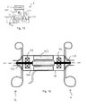
- the system 1 comprises an electric generator 10 and two turbines 11, 12.
- a shaft 100 is rotatably mounted on two bearings 101, 102 and carries the rotor 103 of the generator 10 between the bearings 101, 102 and the wheel 113, 123 of each turbine on either side of the bearings 101, 102.
- wheels 113, 123 may be of a radial type, axial or mixed flow.
- the electric generator 10 comprises cooling means, not shown.
- Each turbine 11, 12 has an inlet 110, 120 and an outlet 111, 121 for the exhaust gas.
- the first turbine 11 receives on its inlet 110 the exhaust gas from the engine via a supply line 13.
- the second turbine 12 receives on its inlet 120 the exhaust gas from the outlet 111 of the first turbine 11 through a transfer line 14.
- the outlet 121 of the second turbine 12 is connected to an exhaust gas network 15, not detailed.
- the gases supplied by the engine E pass through the first turbine 11 and then the second turbine 12 before being evacuated by the exhaust gas exhaust network 15.
- the use of two turbines on the same shaft makes it possible, in comparison with a system according to the prior art with a single turbine, to reduce the size of the turbines 11, 12, and thus to reduce the radial size of the recovery system 1 energy. This one can then more easily be integrated into a power train.
- a turbocharger 16 is interposed between the engine E and the first turbine 11. More specifically, the exhaust gas leaving the engine E passes through a turbine 160 of the turbocharger 16, then the first turbine 11 and finally the second turbine 12, before be evacuated to the exhaust gas discharge network.
- a system 1 of energy recovery is able to also provide charge air to the engine E.
- a discharge valve 17 is placed in parallel with the turbine 160 of the turbocharger 16.
- This discharge valve 17 can be in two states or progressive. It allows to pass some or all of the flow of exhaust gas to the first turbine 11 if the turbocharger 16 does not need more energy to provide the charge air.
- the third variant 1c differs from the first variant 1a by the use of a turbocharger turbine 160 '16' variable geometry. A part of the flow of the exhaust gas can pass through the turbocharger turbine 160 '16 without giving up energy and supplying the first turbine 11.
- a discharge valve 18 is placed in parallel with the first turbine 11.
- the discharge valve 17 makes it possible, for example, to let part of the flow of exhaust gas pass if the electrical energy supplied by the electric generator 10 can not be used and thus reduce the back pressure to the engine exhaust E. Conversely, if a use of the energy recovery system is envisaged to increase the engine brake, this back pressure can be increased to the maximum.
- Another advantage is to be able to provide a first turbine 11 effective for small exhaust gas flow rates and to be able to derive the gas flow by limiting back pressure upstream for high flow rates.
- a discharge valve 19 is placed in parallel with the second turbine 12.
- the advantages are similar to those of the fourth variant 1d.
- a discharge valve 18 is placed in parallel with the first turbine 11 and another discharge valve 19 is placed in parallel with the second turbine 12.
- Another advantage is to be able to choose a first turbine 11 different from the second turbine 12, each being optimal over a different operating range, and to make optionally operate, one or the other of the turbines 11, 12, or the two turbines 11, 12 together.
- the figure 8 represents a seventh variant 1g of the first embodiment, similar to the sixth variant 1f, in which the turbines 11 ", 12 'are of variable geometry, Such means make it possible to optimize the energy recovery over a very wide range of operating the engine E, while improving the efficiency of both the energy recovery system and the engine, as well as its capacity in terms of engine braking.
- a second embodiment of the system 2 according to the invention is proposed in which the turbines 21, 22 are connected in parallel.
- a supply pipe 23 coming from the engine E is subdivided into two and connects firstly to the inlet 210 of the first turbine 22 and secondly to the inlet 220 of the second turbine 22.
- Outlets 211, 221 of the two turbines are connected together and connected to a non-detailed gas evacuation network.
- the use of two turbines 21, 22 on the same shaft makes it possible, in comparison with a system according to the prior art with a single turbine, to reduce the size of the turbines, and thus to reduce the radial size of the recovery system 2. energy. It can then be more easily integrated into a power train.
- the inertia of the two wheels 113, 123 of the turbines is lower than the inertia of a single wheel of the same efficiency as the sum of the two turbines, but larger.
- a first variant 2a of the second embodiment is shown on the figure 10 and proposes two separate exhaust gas networks 25 ', 25 ".
- the branch of the supply line 23 to the second turbine 22 comprises a selection valve 27. It is thus possible to close the exhaust gas supply of the second turbine 22 and to drive the entire flow of gas to the first turbine 21.
- This mode of operation is interesting when the flow is low. In fact, at low flow rates, if the flux is divided by two, the power received by the turbine is divided by a factor greater than two. The efficiency is therefore greater by concentrating the flow towards a single turbine 21. On the other hand, at high flow rates, it is useful to divide the flow in two in order to limit the back pressure upstream of the turbines 21, 22.
- the turbines 21, 22 are not necessarily identical, the first turbine 21 can be chosen to optimize very low flow operation. As soon as the first turbine 21 provides its maximum power, the selection valve 27 is opened to also feed the second turbine 22 and limit the increase in the back pressure. The opening of the selection valve 27 may be progressive or not.
- FIGS 12, 13 and 14 show variants which are developments of the second variant 2b, in which the selection valve 27 is placed downstream of the second turbine 22 (2c, figure 12 ), upstream of the first turbine 21 (2d, figure 13 ) or downstream of the first turbine 21 (2e, figure 14 ).
- the effects are the same and the choices are dictated by implantation constraints, mechanical or thermal resistance or robustness.
- the first turbine 31 is supplied directly by the engine E
- the second turbine 32 is supplied by the engine E via a selection valve 37 connected to a first inlet 320
- a first discharge valve 38 is placed in parallel with the first turbine 31
- a second discharge valve 39 is placed in parallel with the second turbine 32.
- the second turbine 32 further comprises a second inlet 322 connected to the outlet 311 of the first turbine 31.
- bypass valves 38, 39 and selection valves 37 are closed, the turbines 31, 32 are connected in series. If the selection valve 37 is open, the turbines operate in parallel.
- the bypass valves 38, 39 make it possible to limit the backpressure upstream of one or the other of the turbines 31, 32. This arrangement allows multiple modes of operation, the advantages of which can be combined as a function of the flow of the gases. exhaust.
- At least one of the turbines may comprise at least two wheels and at least one of the turbines may be of variable geometry type, whatever its principle of embodiment.
Landscapes
- Engineering & Computer Science (AREA)
- Mechanical Engineering (AREA)
- General Engineering & Computer Science (AREA)
- Chemical & Material Sciences (AREA)
- Combustion & Propulsion (AREA)
- Supercharger (AREA)
Applications Claiming Priority (1)
| Application Number | Priority Date | Filing Date | Title |
|---|---|---|---|
| FR0954710A FR2947860A1 (fr) | 2009-07-08 | 2009-07-08 | Systeme de generatrice electrique et turbine pour la recuperation d'energie contenue dans les gaz d'echappement d'un moteur thermique. |
Publications (1)
| Publication Number | Publication Date |
|---|---|
| EP2273085A1 true EP2273085A1 (de) | 2011-01-12 |
Family
ID=41629309
Family Applications (1)
| Application Number | Title | Priority Date | Filing Date |
|---|---|---|---|
| EP10168578A Withdrawn EP2273085A1 (de) | 2009-07-08 | 2010-07-06 | System mit Stromgenerator und in Abgas einer Wärmekraftmaschine enthaltener Energierückgewinnungsturbine |
Country Status (2)
| Country | Link |
|---|---|
| EP (1) | EP2273085A1 (de) |
| FR (1) | FR2947860A1 (de) |
Cited By (2)
| Publication number | Priority date | Publication date | Assignee | Title |
|---|---|---|---|---|
| GB2526090A (en) * | 2014-05-12 | 2015-11-18 | Cummins Ltd | Turbine generator |
| CN113006887A (zh) * | 2021-03-22 | 2021-06-22 | 安徽新宁能源科技有限公司 | 一种汽轮机 |
Citations (4)
| Publication number | Priority date | Publication date | Assignee | Title |
|---|---|---|---|---|
| EP0349211A1 (de) * | 1988-06-29 | 1990-01-03 | Isuzu Motors Limited | Abgasbetriebener Generator für Verbrennungsmotoren |
| GB2292587A (en) * | 1994-08-25 | 1996-02-28 | James Neville Randle | Turbocharged internal combustion engine arrangement |
| EP1355051A2 (de) | 2002-04-18 | 2003-10-22 | Deere & Company | Energierückgewinnungssystem |
| EP2006506A1 (de) * | 2007-06-22 | 2008-12-24 | ABB Turbo Systems AG | Aufladesystem für Brennkraftmaschine |
-
2009
- 2009-07-08 FR FR0954710A patent/FR2947860A1/fr active Pending
-
2010
- 2010-07-06 EP EP10168578A patent/EP2273085A1/de not_active Withdrawn
Patent Citations (4)
| Publication number | Priority date | Publication date | Assignee | Title |
|---|---|---|---|---|
| EP0349211A1 (de) * | 1988-06-29 | 1990-01-03 | Isuzu Motors Limited | Abgasbetriebener Generator für Verbrennungsmotoren |
| GB2292587A (en) * | 1994-08-25 | 1996-02-28 | James Neville Randle | Turbocharged internal combustion engine arrangement |
| EP1355051A2 (de) | 2002-04-18 | 2003-10-22 | Deere & Company | Energierückgewinnungssystem |
| EP2006506A1 (de) * | 2007-06-22 | 2008-12-24 | ABB Turbo Systems AG | Aufladesystem für Brennkraftmaschine |
Cited By (4)
| Publication number | Priority date | Publication date | Assignee | Title |
|---|---|---|---|---|
| GB2526090A (en) * | 2014-05-12 | 2015-11-18 | Cummins Ltd | Turbine generator |
| GB2526090B (en) * | 2014-05-12 | 2020-10-07 | Cummins Ltd | Turbine generator |
| CN113006887A (zh) * | 2021-03-22 | 2021-06-22 | 安徽新宁能源科技有限公司 | 一种汽轮机 |
| CN113006887B (zh) * | 2021-03-22 | 2024-07-02 | 安徽新宁能源科技有限公司 | 一种汽轮机 |
Also Published As
| Publication number | Publication date |
|---|---|
| FR2947860A1 (fr) | 2011-01-14 |
Similar Documents
| Publication | Publication Date | Title |
|---|---|---|
| EP1460248B1 (de) | Aufgeladene Brennkraftmaschine mit elektrisch unterstüztem Turbolader | |
| FR2919895A1 (fr) | Dispositif de suralimentation d'un moteur a combustion interne. | |
| FR2611229A1 (fr) | Turboreacteur a soufflante carenee a cycle compound | |
| WO2005073536A1 (fr) | Moteur a combustion interne suralimente par turbocompresseur | |
| FR2916226A3 (fr) | Moteur a combustion interne suralimente et systeme de distribution variable avec suralimentation pour un tel moteur | |
| EP2273085A1 (de) | System mit Stromgenerator und in Abgas einer Wärmekraftmaschine enthaltener Energierückgewinnungsturbine | |
| EP1654448B1 (de) | Aufgeladener motor mit mindestens zwei turboladerstufen | |
| FR2922595A1 (fr) | Moteur a combustion interne equipe d'un groupe de suralimentation a deux etages | |
| EP3256706A1 (de) | Aufgeladene motoranordnung mit zwei abgaskanälen mit schnellem regelventil | |
| FR2884866A1 (fr) | Moteur a suralimentation sequentielle et a distribution variable | |
| FR3056194A1 (fr) | Unite d'alimentation en air sous pression pour aeronef | |
| FR2875849A1 (fr) | Procede de fonctionnement d'un moteur a combustion interne comprenant un compresseur a ondes de pression | |
| EP3179070B1 (de) | Motorsystem mit energierückgewinnungssystem | |
| FR2872858A1 (fr) | Moteur thermique suralimente a compresseur additionnel | |
| FR3028243A1 (fr) | Systeme de propulsion comportant un moteur a combustion interne et une turbomachine | |
| FR3063780A1 (fr) | Compresseur electrique avec circuit de refroidissement | |
| FR3032487A1 (fr) | Ensemble moteur turbocompresse a deux conduits d’echappement avec ligne de recirculation et dispositif de regulation | |
| FR2891310A3 (fr) | Suralimentation d'un moteur par combinaison appropriee d'un turbocompresseur et d'un compresseur a ondes de pression | |
| EP3375074A1 (de) | Elektrischer kompressor mit einem kühlkreislauf | |
| FR3015564A1 (fr) | Procede de controle de la decharge d'une turbine de turbocompresseur | |
| FR3044363B1 (fr) | Systeme moteur avec circuit de recirculation des gaz brules | |
| WO2017093661A1 (fr) | Systeme moteur avec systeme de recuperation d'energie et circuit basse pression de recirculation des gaz brules | |
| FR3044366B1 (fr) | Systeme moteur avec circuit de recirculation des gaz brules | |
| FR3032485A1 (fr) | Ensemble moteur turbocompresse a deux conduits d’echappement avec ligne de recirculation | |
| FR3029567A1 (fr) | Turbocompresseur compact pour moteur thermique de vehicule automobile |
Legal Events
| Date | Code | Title | Description |
|---|---|---|---|
| PUAI | Public reference made under article 153(3) epc to a published international application that has entered the european phase |
Free format text: ORIGINAL CODE: 0009012 |
|
| AK | Designated contracting states |
Kind code of ref document: A1 Designated state(s): AL AT BE BG CH CY CZ DE DK EE ES FI FR GB GR HR HU IE IS IT LI LT LU LV MC MK MT NL NO PL PT RO SE SI SK SM TR |
|
| AX | Request for extension of the european patent |
Extension state: BA ME RS |
|
| 17P | Request for examination filed |
Effective date: 20110707 |
|
| 17Q | First examination report despatched |
Effective date: 20151211 |
|
| STAA | Information on the status of an ep patent application or granted ep patent |
Free format text: STATUS: THE APPLICATION IS DEEMED TO BE WITHDRAWN |
|
| 18D | Application deemed to be withdrawn |
Effective date: 20160422 |