EP2273106A2 - Contrôle de la séparation aerodynamique d'éolienne - Google Patents
Contrôle de la séparation aerodynamique d'éolienne Download PDFInfo
- Publication number
- EP2273106A2 EP2273106A2 EP10168614A EP10168614A EP2273106A2 EP 2273106 A2 EP2273106 A2 EP 2273106A2 EP 10168614 A EP10168614 A EP 10168614A EP 10168614 A EP10168614 A EP 10168614A EP 2273106 A2 EP2273106 A2 EP 2273106A2
- Authority
- EP
- European Patent Office
- Prior art keywords
- wind speed
- wind
- blades
- speed sensors
- controller
- Prior art date
- Legal status (The legal status is an assumption and is not a legal conclusion. Google has not performed a legal analysis and makes no representation as to the accuracy of the status listed.)
- Granted
Links
Images

Classifications
-
- F—MECHANICAL ENGINEERING; LIGHTING; HEATING; WEAPONS; BLASTING
- F03—MACHINES OR ENGINES FOR LIQUIDS; WIND, SPRING, OR WEIGHT MOTORS; PRODUCING MECHANICAL POWER OR A REACTIVE PROPULSIVE THRUST, NOT OTHERWISE PROVIDED FOR
- F03D—WIND MOTORS
- F03D7/00—Controlling wind motors
- F03D7/02—Controlling wind motors the wind motors having rotation axis substantially parallel to the air flow entering the rotor
- F03D7/04—Automatic control; Regulation
- F03D7/042—Automatic control; Regulation by means of an electrical or electronic controller
-
- F—MECHANICAL ENGINEERING; LIGHTING; HEATING; WEAPONS; BLASTING
- F03—MACHINES OR ENGINES FOR LIQUIDS; WIND, SPRING, OR WEIGHT MOTORS; PRODUCING MECHANICAL POWER OR A REACTIVE PROPULSIVE THRUST, NOT OTHERWISE PROVIDED FOR
- F03D—WIND MOTORS
- F03D7/00—Controlling wind motors
- F03D7/02—Controlling wind motors the wind motors having rotation axis substantially parallel to the air flow entering the rotor
- F03D7/0204—Controlling wind motors the wind motors having rotation axis substantially parallel to the air flow entering the rotor for orientation in relation to wind direction
-
- F—MECHANICAL ENGINEERING; LIGHTING; HEATING; WEAPONS; BLASTING
- F03—MACHINES OR ENGINES FOR LIQUIDS; WIND, SPRING, OR WEIGHT MOTORS; PRODUCING MECHANICAL POWER OR A REACTIVE PROPULSIVE THRUST, NOT OTHERWISE PROVIDED FOR
- F03D—WIND MOTORS
- F03D7/00—Controlling wind motors
- F03D7/02—Controlling wind motors the wind motors having rotation axis substantially parallel to the air flow entering the rotor
- F03D7/022—Adjusting aerodynamic properties of the blades
- F03D7/0224—Adjusting blade pitch
-
- G—PHYSICS
- G01—MEASURING; TESTING
- G01P—MEASURING LINEAR OR ANGULAR SPEED, ACCELERATION, DECELERATION, OR SHOCK; INDICATING PRESENCE, ABSENCE, OR DIRECTION, OF MOVEMENT
- G01P5/00—Measuring speed of fluids, e.g. of air stream; Measuring speed of bodies relative to fluids, e.g. of ship, of aircraft
- G01P5/02—Measuring speed of fluids, e.g. of air stream; Measuring speed of bodies relative to fluids, e.g. of ship, of aircraft by measuring forces exerted by the fluid on solid bodies, e.g. anemometer
-
- F—MECHANICAL ENGINEERING; LIGHTING; HEATING; WEAPONS; BLASTING
- F05—INDEXING SCHEMES RELATING TO ENGINES OR PUMPS IN VARIOUS SUBCLASSES OF CLASSES F01-F04
- F05B—INDEXING SCHEME RELATING TO WIND, SPRING, WEIGHT, INERTIA OR LIKE MOTORS, TO MACHINES OR ENGINES FOR LIQUIDS COVERED BY SUBCLASSES F03B, F03D AND F03G
- F05B2240/00—Components
- F05B2240/40—Use of a multiplicity of similar components
-
- F—MECHANICAL ENGINEERING; LIGHTING; HEATING; WEAPONS; BLASTING
- F05—INDEXING SCHEMES RELATING TO ENGINES OR PUMPS IN VARIOUS SUBCLASSES OF CLASSES F01-F04
- F05B—INDEXING SCHEME RELATING TO WIND, SPRING, WEIGHT, INERTIA OR LIKE MOTORS, TO MACHINES OR ENGINES FOR LIQUIDS COVERED BY SUBCLASSES F03B, F03D AND F03G
- F05B2260/00—Function
- F05B2260/70—Adjusting of angle of incidence or attack of rotating blades
- F05B2260/71—Adjusting of angle of incidence or attack of rotating blades as a function of flow velocity
-
- F—MECHANICAL ENGINEERING; LIGHTING; HEATING; WEAPONS; BLASTING
- F05—INDEXING SCHEMES RELATING TO ENGINES OR PUMPS IN VARIOUS SUBCLASSES OF CLASSES F01-F04
- F05B—INDEXING SCHEME RELATING TO WIND, SPRING, WEIGHT, INERTIA OR LIKE MOTORS, TO MACHINES OR ENGINES FOR LIQUIDS COVERED BY SUBCLASSES F03B, F03D AND F03G
- F05B2270/00—Control
- F05B2270/30—Control parameters, e.g. input parameters
- F05B2270/32—Wind speeds
-
- F—MECHANICAL ENGINEERING; LIGHTING; HEATING; WEAPONS; BLASTING
- F05—INDEXING SCHEMES RELATING TO ENGINES OR PUMPS IN VARIOUS SUBCLASSES OF CLASSES F01-F04
- F05B—INDEXING SCHEME RELATING TO WIND, SPRING, WEIGHT, INERTIA OR LIKE MOTORS, TO MACHINES OR ENGINES FOR LIQUIDS COVERED BY SUBCLASSES F03B, F03D AND F03G
- F05B2270/00—Control
- F05B2270/30—Control parameters, e.g. input parameters
- F05B2270/336—Blade lift measurements
-
- F—MECHANICAL ENGINEERING; LIGHTING; HEATING; WEAPONS; BLASTING
- F05—INDEXING SCHEMES RELATING TO ENGINES OR PUMPS IN VARIOUS SUBCLASSES OF CLASSES F01-F04
- F05B—INDEXING SCHEME RELATING TO WIND, SPRING, WEIGHT, INERTIA OR LIKE MOTORS, TO MACHINES OR ENGINES FOR LIQUIDS COVERED BY SUBCLASSES F03B, F03D AND F03G
- F05B2270/00—Control
- F05B2270/80—Devices generating input signals, e.g. transducers, sensors, cameras or strain gauges
- F05B2270/804—Optical devices
-
- Y—GENERAL TAGGING OF NEW TECHNOLOGICAL DEVELOPMENTS; GENERAL TAGGING OF CROSS-SECTIONAL TECHNOLOGIES SPANNING OVER SEVERAL SECTIONS OF THE IPC; TECHNICAL SUBJECTS COVERED BY FORMER USPC CROSS-REFERENCE ART COLLECTIONS [XRACs] AND DIGESTS
- Y02—TECHNOLOGIES OR APPLICATIONS FOR MITIGATION OR ADAPTATION AGAINST CLIMATE CHANGE
- Y02E—REDUCTION OF GREENHOUSE GAS [GHG] EMISSIONS, RELATED TO ENERGY GENERATION, TRANSMISSION OR DISTRIBUTION
- Y02E10/00—Energy generation through renewable energy sources
- Y02E10/70—Wind energy
- Y02E10/72—Wind turbines with rotation axis in wind direction
Definitions
- the present application relates generally to the field of wind turbines and more particularly relates to the use of fiber optic sensors to determine the wind speed along the length of an airfoil blade.
- Wind turbines are increasingly gaining importance in the area of renewable sources of energy generation. Wind turbine technology is now the basis of large scale power generation applications. Of the many challenges that exist in harnessing wind energy, one challenge is maximizing wind turbine performance while minimizing system loads in given wind conditions. Non-limiting examples of improved wind turbine performance parameters include maximized aerodynamic efficiency, maximized energy output, minimized wind turbine system loads, minimized noise, and combinations thereof. Improvement in these parameters may lead to a minimized cost of energy and other benefits.
- Flow separation may lead to stall, which is a limiting factor in wind turbine blade design.
- stall occurs, lift generated by the blades may decrease significantly and a large component of the torque, which is the driving force imparted by the wind to the wind turbine, may be lost. Solutions that provide an ability to control flow separation, i.e., diminish or delay the separation, may allow the wind turbine blades to maximize lift.
- the present application thus provides a wind turbine system.
- the wind turbine system may include a number of blades, a number of wind speed sensors positioned on the blades, a controller in communication with the wind speed sensors, and one or more performance adjustment mechanisms in communication with the controller.
- the controller activates the performance adjustment mechanisms in response to the wind speed sensors.
- the one or more performance adjustment mechanisms of the wind turbine system may include a yaw mechanism.
- the one or more performance adjustment mechanisms may include a blade pitch mechanism.
- the plurality of wind speed sensors may include a plurality of fiber optic sensors positioned along a cable.
- the controller may include a wind speed profile based upon an output of the plurality of wind speed sensors.
- the controller may also include a plurality of expected aerodynamic profiles for the plurality of blades.
- the present application further provides a method of operating a wind turbine having a number of wind speed sensors positioned along a number of turbine blades and having a number of performance adjustment mechanisms.
- the method includes the steps of sensing the wind speed at a number of locations along the turbine blades, developing a wind speed profile for the turbine blades, comparing the wind speed profile to an expected aerodynamic profile, and activating one or more of the performance adjustment mechanisms to compensate for a variation between the wind speed profile and the expected aerodynamic profile.
- the step of activating one or more of the number of performance adjustment mechanisms may include activating a yaw mechanism. Moreover, the step of activating one or more of the number of performance adjustment mechanisms may include activating a blade pitch mechanism.
- the number of wind speed sensors may include a number of fiber optic wind speed sensors and wherein the step of sensing the wind speed may include sensing a wind induced strain in the number of fiber optic wind speed sensors.
- the comparing step may include determining areas of flow separation along one of the number of turbine blades. The step may also include determining at least one of pitch angle, rotational speed, or torque demand on the number of turbine blades.
- the present application further provides a wind turbine system.
- the wind turbine system may include a number of blades, a number of fiber optic wind speed sensors positioned on the blades, a controller in communication with the fiber optic wind speed sensors, and a yaw mechanism and a blade pitch mechanism in communication with the controller.
- the controller activates the yaw mechanism and/or the blade pitch mechanism in response to the fiber optic wind speed sensors.
- the controller may include a wind speed profile based upon an output of the plurality of fiber optic wind speed sensors.
- the controller may additionally include a plurality of expected aerodynamic profiles for the plurality of blades.
- Fig. 1 shows a wind turbine 100 as is described herein.
- the wind turbine 100 includes a number of turbine blades 110.
- the turbine blades 110 may have any desired size or shape. Any number of turbine blades 110 may be used.
- the turbine blades 110 are configured to rotate about an axis 120 with an incident wind flow such as a wind flow 130 as is shown.
- the axis of rotation 120 is along the z-axis and the plane of rotation of the turbine blades 110 is the x-y plane with the x-axis coming out of the plane of the paper.
- the wind turbine 100 may include a wind turbine generator 140.
- the wind turbine generator 140 converts mechanical energy to electrical energy.
- the wind turbine 100 further may include a gear mechanism 150.
- the gear mechanism 150 provides the mechanical energy harnessed from the wind turbine blades 110 to the wind turbine generator 140.
- the wind turbine 100 further may include a yaw mechanism 160, a blade pitch mechanism 170, and/or other types of performance adjustment mechanisms 180.
- a controller 190 may be responsive to the current operating conditions of the overall wind turbine 100.
- the controller 190 may be coupled to the generator 140, the yaw mechanism 160, the blade pitch control mechanism 170, other performance adjustment mechanisms 180, and other devices for controlling the operation of the overall wind turbine 100.
- Other systems, controls, devices, and wind turbine designs may be used herein.
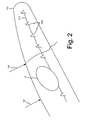
- the turbine blades 110 of the wind turbine 100 may include a number of wind speed sensors 200 positioned along a cable 210.
- the wind speed sensors 200 may be fiber optic sensors and the like.
- the wind speed sensors 200 may be positioned on or about the suction side of each turbine blade 110 along about 90 to 95% of chord or so. Other types of positioning may be used herein. Any number of wind speed sensors 200 may be used. Other types of sensors 200 may be used herein.
- the wind speed sensors 200 and the cable 210 may be in communication with the controller 190.
- the wind speed sensors 200 may develop a wind induced strain that can be measured optically and/or electronically using, for example, a fiber optic Bragg sensor or a similar type of technology.
- the strain may be correlated to a wind speed at the location of the particular sensor 200.
- Several sensors 200 may be implemented along the blade 110 such that a wind speed profile 220 for the length of the blade 110 may be measured and developed.
- the measured wind speed profile then may be compared by the controller 190 to an expected aerodynamic profile 230 for the given pitch angle, the rotational speed, the torque demand on the blade 110, and other parameters.
- the controller 190 thus may have any number of expected aerodynamic profiles 230 available. Other parameters also may be measured and considered.
- the wind speed profiles 220 of the other turbine blades 110 also may be compared and controlled.
- the radial location of flow separations S may be determined. Specifically, the attached flow should have a higher wind speed as compared to the separated flow.
- the separation S locations on all of the blades 110 may be compared by the controller 190 such that the yaw mechanism 160 and the blade pitch mechanism 170 may be activated so as to "fly out” the differences.
- the pitch of the individual blades 110 may be varied, the direction in which the wind turbine 100 is facing may change (yaw), the torque demand of the generator 140 may change, or combinations thereof.
- Other performance or operational parameters also may be varied.
- the yaw mechanism 160 may be used to redirect the wind turbine 100 to minimize or eliminate this separation behavior. Balancing where the flow separates between the several blades 110 may decrease loads and increase power generation performance as well as reduce the effects of up flow angle turbulence. Once the yaw, the blade pitch, and/or other parameters have been altered, the process may repeat so as to continue to reduce or delay the separations S and to maximize overall performance.
- the controller 190 may have an expected aerodynamic profile 230 and may sense how close the actual measured wind speed profile 220 may be to the optimal expected aerodynamic profile 230. For example, when a blade 110 rotates into higher winds (due to wind shear), separation may move toward the tip of the blade 110. The controller 190 may compensate by pitching the blade 110 slightly towards a feathered position. Alternately, if all of the blades 110 face separation moving too far toward the tip, the pitch of all of the blades 110 or the torque demand of the generator 140 may be changed to improve the flow field and power output.
- the controller 190 may be able to "fly out” the differences among the blades 110 with the blade pitch mechanism 170.
- the turbine 100 may be able to tell if it is actually facing the wind so as to reduce yaw error. Such capability should increase energy capture and customer value.
- the same data also may be used to reduce loads on the rotor, allowing the blades 110 to be increased in area, run in higher wind classes, or reduce weight with respect to the supporting mechanical structure.
Landscapes
- Engineering & Computer Science (AREA)
- Mechanical Engineering (AREA)
- Sustainable Development (AREA)
- Sustainable Energy (AREA)
- Chemical & Material Sciences (AREA)
- Combustion & Propulsion (AREA)
- Life Sciences & Earth Sciences (AREA)
- General Engineering & Computer Science (AREA)
- Physics & Mathematics (AREA)
- Aviation & Aerospace Engineering (AREA)
- General Physics & Mathematics (AREA)
- Fluid Mechanics (AREA)
- Wind Motors (AREA)
Applications Claiming Priority (1)
| Application Number | Priority Date | Filing Date | Title |
|---|---|---|---|
| US12/500,648 US8002524B2 (en) | 2009-07-10 | 2009-07-10 | Wind turbine aerodynamic separation control |
Publications (3)
| Publication Number | Publication Date |
|---|---|
| EP2273106A2 true EP2273106A2 (fr) | 2011-01-12 |
| EP2273106A3 EP2273106A3 (fr) | 2014-04-02 |
| EP2273106B1 EP2273106B1 (fr) | 2016-09-07 |
Family
ID=42231270
Family Applications (1)
| Application Number | Title | Priority Date | Filing Date |
|---|---|---|---|
| EP10168614.5A Active EP2273106B1 (fr) | 2009-07-10 | 2010-07-06 | Contrôle de la séparation aérodynamique d'éolienne |
Country Status (4)
| Country | Link |
|---|---|
| US (1) | US8002524B2 (fr) |
| EP (1) | EP2273106B1 (fr) |
| CN (1) | CN101956659B (fr) |
| DK (1) | DK2273106T3 (fr) |
Cited By (1)
| Publication number | Priority date | Publication date | Assignee | Title |
|---|---|---|---|---|
| AT526977A1 (de) * | 2023-02-15 | 2024-09-15 | Windpuls Gmbh | Vorrichtung zum Messen von Windanströmungsbedingungen |
Families Citing this family (9)
| Publication number | Priority date | Publication date | Assignee | Title |
|---|---|---|---|---|
| TW201100634A (en) * | 2009-06-22 | 2011-01-01 | Power Light Tech Co Ltd | Solar and wind power generator for tracking light automatically |
| US8057175B2 (en) * | 2010-11-11 | 2011-11-15 | General Electric Company | Active control of a wind turbine blade |
| US8240993B2 (en) * | 2011-01-04 | 2012-08-14 | General Electric Company | System and method of manipulating a boundary layer across a rotor blade of a wind turbine |
| CN102619683A (zh) * | 2011-01-30 | 2012-08-01 | 华锐风电科技(集团)股份有限公司 | 一种风力发电机变桨与偏航的分布式控制系统 |
| ES2397468B1 (es) * | 2011-07-27 | 2013-11-21 | Investigaciones Y Desarrollos Eólicos, S.L. | Equipo para la estimación de demandas de angulo de pitch o velocidad de angulo de pitch independiente para cada pala en aerogeneradores |
| US9753050B2 (en) * | 2013-02-15 | 2017-09-05 | Vestas Wind Systems A/S | Wind turbine component having an optical fibre wind sensor |
| US9004851B1 (en) * | 2014-03-05 | 2015-04-14 | Gustavo Q. Garza | Efficient spiral wind-turbine configuration |
| DE102015121981A1 (de) * | 2015-12-16 | 2017-06-22 | fos4X GmbH | Verfahren und Vorrichtung zum Betreiben einer Windkraftanlage |
| US11408394B2 (en) | 2018-09-17 | 2022-08-09 | Siemens Gamesa Renewable Energy A/S | Sensor device for an aerodynamic element |
Family Cites Families (17)
| Publication number | Priority date | Publication date | Assignee | Title |
|---|---|---|---|---|
| DE3000678A1 (de) * | 1980-01-10 | 1981-07-16 | Erno Raumfahrttechnik Gmbh, 2800 Bremen | Vorrichtung zur bestimmung der windenergie zur regelung von windkraftwerken |
| US5394488A (en) * | 1993-11-30 | 1995-02-28 | United Technologies Corporation | Optical fiber grating based sensor |
| ES2228121T3 (es) * | 1999-11-03 | 2005-04-01 | Vestas Wind Systems A/S | Procedimiento de control de la operacion de una turbina electrica y turbina electrica para usarse en dicho procedimiento. |
| CA2426711C (fr) | 2002-05-02 | 2009-11-17 | General Electric Company | Centrale eolienne, mecanisme de commande de centrale eolienne et methode d'exploitation d'une centrale eolienne |
| EP1597476A1 (fr) | 2003-02-18 | 2005-11-23 | Forskningscenter Riso | Methode de commande de la charge aerodynamique d'une eolienne en fonction de la mesure de l'ecoulement local au niveau des pales |
| US7387491B2 (en) | 2004-12-23 | 2008-06-17 | General Electric Company | Active flow modifications on wind turbine blades |
| US7303373B2 (en) | 2005-10-31 | 2007-12-04 | General Electric Company | Wind turbine systems, monitoring systems and processes for monitoring stress in a wind turbine blade |
| US7360996B2 (en) | 2005-12-07 | 2008-04-22 | General Electric Company | Wind blade assembly and method for damping load or strain |
| GB2440953B (en) | 2006-08-18 | 2009-09-30 | Insensys Ltd | Wind turbines |
| GB2440955A (en) | 2006-08-18 | 2008-02-20 | Insensys Ltd | Wind turbine blade monitoring |
| GB2440954B (en) | 2006-08-18 | 2008-12-17 | Insensys Ltd | Structural monitoring |
| DE102006041461A1 (de) * | 2006-09-04 | 2008-03-20 | Siemens Ag | Windenergieanlage mit einer Windgeschwindigkeitsmessvorrichtung zur Bestimmung einer Geschwindigkeit des die Windenergieanlage anströmenden Windes |
| DK1988284T5 (da) * | 2007-05-03 | 2019-09-30 | Siemens Gamesa Renewable Energy As | Fremgangsmåde til at drive en vindmølle og vindmølle |
| US7909575B2 (en) | 2007-06-25 | 2011-03-22 | General Electric Company | Power loss reduction in turbulent wind for a wind turbine using localized sensing and control |
| US8408871B2 (en) * | 2008-06-13 | 2013-04-02 | General Electric Company | Method and apparatus for measuring air flow condition at a wind turbine blade |
| US8096761B2 (en) * | 2008-10-16 | 2012-01-17 | General Electric Company | Blade pitch management method and system |
| EP2180183A1 (fr) * | 2008-10-23 | 2010-04-28 | Siemens Aktiengesellschaft | Détection de blocage par l'utilisation de capteurs de pression |
-
2009
- 2009-07-10 US US12/500,648 patent/US8002524B2/en active Active
-
2010
- 2010-07-06 DK DK10168614.5T patent/DK2273106T3/en active
- 2010-07-06 EP EP10168614.5A patent/EP2273106B1/fr active Active
- 2010-07-09 CN CN201010231252.7A patent/CN101956659B/zh active Active
Non-Patent Citations (1)
| Title |
|---|
| None |
Cited By (1)
| Publication number | Priority date | Publication date | Assignee | Title |
|---|---|---|---|---|
| AT526977A1 (de) * | 2023-02-15 | 2024-09-15 | Windpuls Gmbh | Vorrichtung zum Messen von Windanströmungsbedingungen |
Also Published As
| Publication number | Publication date |
|---|---|
| EP2273106B1 (fr) | 2016-09-07 |
| CN101956659A (zh) | 2011-01-26 |
| CN101956659B (zh) | 2015-03-25 |
| EP2273106A3 (fr) | 2014-04-02 |
| US8002524B2 (en) | 2011-08-23 |
| US20100143118A1 (en) | 2010-06-10 |
| DK2273106T3 (en) | 2016-10-24 |
Similar Documents
| Publication | Publication Date | Title |
|---|---|---|
| EP2273106B1 (fr) | Contrôle de la séparation aérodynamique d'éolienne | |
| CN101943116B (zh) | 用于风力涡轮机的噪声受控的运行的方法和系统 | |
| CN101368541B (zh) | 利用逆风信息降低水平轴风力涡轮机中负荷的系统和方法 | |
| DK2306003T3 (en) | System and methods for controlling a wind turbine | |
| AU2007303956B2 (en) | Wind turbine with blade pitch control to compensate for wind shear and wind misalignment | |
| EP2670979B1 (fr) | Systèmes et méthode de commande d'une turbine éolienne | |
| US8096761B2 (en) | Blade pitch management method and system | |
| DK1870596T3 (en) | Device for balancing a rotor | |
| EP2306007B1 (fr) | Procédé et Système pour la régulation d'une Éolienne | |
| Cooperman et al. | Load monitoring for active control of wind turbines | |
| DK1906192T3 (en) | Apparatus for evaluating sensors and / or for controlling the operation of an apparatus which includes a sensor | |
| CN102933841B (zh) | 风力涡轮机 | |
| DK2287464T3 (en) | Passive de-icing for wind turbine blades | |
| DK2381098T3 (en) | Method of measuring a rotational position of a rotor blade of a wind turbine and measuring device | |
| EP2167814B1 (fr) | Commande d'un rotor pendant un processus d'arrêt d'une éolienne | |
| DK177188B1 (en) | Method and apparatus for controlling the tip speed of a blade of a wind turbine | |
| DK2757252T3 (en) | Procedure for operating a wind turbine | |
| EP2644887A2 (fr) | Procédé de prévention de décrochage aérodynamique dans des turbines éoliennes | |
| DK2522853T3 (en) | Wind turbine torque-speed control | |
| EP1230479A1 (fr) | Procede pour commander le fonctionnement d'une eolienne et eolienne utilisee dans ce procede | |
| US20120076651A1 (en) | Method of and device for determining a mass condition of a rotor of a wind turbine, and method of operating a wind turbine | |
| CN103906921A (zh) | 用于确定风力涡轮机的偏转角误差的方法和设备和风力涡轮机 | |
| CN115585101A (zh) | 风力涡轮中的方位传感器 | |
| Eggers, Jr et al. | Modeling of yawing and furling behavior of small wind turbines | |
| JP2019100262A (ja) | 風力発電装置の評価方法および設計方法 |
Legal Events
| Date | Code | Title | Description |
|---|---|---|---|
| PUAI | Public reference made under article 153(3) epc to a published international application that has entered the european phase |
Free format text: ORIGINAL CODE: 0009012 |
|
| AK | Designated contracting states |
Kind code of ref document: A2 Designated state(s): AL AT BE BG CH CY CZ DE DK EE ES FI FR GB GR HR HU IE IS IT LI LT LU LV MC MK MT NL NO PL PT RO SE SI SK SM TR |
|
| AX | Request for extension of the european patent |
Extension state: BA ME RS |
|
| PUAL | Search report despatched |
Free format text: ORIGINAL CODE: 0009013 |
|
| AK | Designated contracting states |
Kind code of ref document: A3 Designated state(s): AL AT BE BG CH CY CZ DE DK EE ES FI FR GB GR HR HU IE IS IT LI LT LU LV MC MK MT NL NO PL PT RO SE SI SK SM TR |
|
| AX | Request for extension of the european patent |
Extension state: BA ME RS |
|
| RIC1 | Information provided on ipc code assigned before grant |
Ipc: F03D 7/04 20060101AFI20140221BHEP Ipc: F03D 7/02 20060101ALI20140221BHEP |
|
| 17P | Request for examination filed |
Effective date: 20141002 |
|
| RBV | Designated contracting states (corrected) |
Designated state(s): AL AT BE BG CH CY CZ DE DK EE ES FI FR GB GR HR HU IE IS IT LI LT LU LV MC MK MT NL NO PL PT RO SE SI SK SM TR |
|
| 17Q | First examination report despatched |
Effective date: 20150225 |
|
| GRAP | Despatch of communication of intention to grant a patent |
Free format text: ORIGINAL CODE: EPIDOSNIGR1 |
|
| INTG | Intention to grant announced |
Effective date: 20160406 |
|
| GRAS | Grant fee paid |
Free format text: ORIGINAL CODE: EPIDOSNIGR3 |
|
| GRAA | (expected) grant |
Free format text: ORIGINAL CODE: 0009210 |
|
| AK | Designated contracting states |
Kind code of ref document: B1 Designated state(s): AL AT BE BG CH CY CZ DE DK EE ES FI FR GB GR HR HU IE IS IT LI LT LU LV MC MK MT NL NO PL PT RO SE SI SK SM TR |
|
| REG | Reference to a national code |
Ref country code: GB Ref legal event code: FG4D |
|
| REG | Reference to a national code |
Ref country code: CH Ref legal event code: EP |
|
| REG | Reference to a national code |
Ref country code: IE Ref legal event code: FG4D |
|
| REG | Reference to a national code |
Ref country code: AT Ref legal event code: REF Ref document number: 827123 Country of ref document: AT Kind code of ref document: T Effective date: 20161015 |
|
| REG | Reference to a national code |
Ref country code: DE Ref legal event code: R096 Ref document number: 602010036146 Country of ref document: DE |
|
| REG | Reference to a national code |
Ref country code: DK Ref legal event code: T3 Effective date: 20161021 |
|
| REG | Reference to a national code |
Ref country code: LT Ref legal event code: MG4D |
|
| REG | Reference to a national code |
Ref country code: NL Ref legal event code: MP Effective date: 20160907 |
|
| PG25 | Lapsed in a contracting state [announced via postgrant information from national office to epo] |
Ref country code: NO Free format text: LAPSE BECAUSE OF FAILURE TO SUBMIT A TRANSLATION OF THE DESCRIPTION OR TO PAY THE FEE WITHIN THE PRESCRIBED TIME-LIMIT Effective date: 20161207 Ref country code: LT Free format text: LAPSE BECAUSE OF FAILURE TO SUBMIT A TRANSLATION OF THE DESCRIPTION OR TO PAY THE FEE WITHIN THE PRESCRIBED TIME-LIMIT Effective date: 20160907 Ref country code: FI Free format text: LAPSE BECAUSE OF FAILURE TO SUBMIT A TRANSLATION OF THE DESCRIPTION OR TO PAY THE FEE WITHIN THE PRESCRIBED TIME-LIMIT Effective date: 20160907 Ref country code: HR Free format text: LAPSE BECAUSE OF FAILURE TO SUBMIT A TRANSLATION OF THE DESCRIPTION OR TO PAY THE FEE WITHIN THE PRESCRIBED TIME-LIMIT Effective date: 20160907 |
|
| REG | Reference to a national code |
Ref country code: AT Ref legal event code: MK05 Ref document number: 827123 Country of ref document: AT Kind code of ref document: T Effective date: 20160907 |
|
| PG25 | Lapsed in a contracting state [announced via postgrant information from national office to epo] |
Ref country code: ES Free format text: LAPSE BECAUSE OF FAILURE TO SUBMIT A TRANSLATION OF THE DESCRIPTION OR TO PAY THE FEE WITHIN THE PRESCRIBED TIME-LIMIT Effective date: 20160907 Ref country code: GR Free format text: LAPSE BECAUSE OF FAILURE TO SUBMIT A TRANSLATION OF THE DESCRIPTION OR TO PAY THE FEE WITHIN THE PRESCRIBED TIME-LIMIT Effective date: 20161208 Ref country code: LV Free format text: LAPSE BECAUSE OF FAILURE TO SUBMIT A TRANSLATION OF THE DESCRIPTION OR TO PAY THE FEE WITHIN THE PRESCRIBED TIME-LIMIT Effective date: 20160907 Ref country code: NL Free format text: LAPSE BECAUSE OF FAILURE TO SUBMIT A TRANSLATION OF THE DESCRIPTION OR TO PAY THE FEE WITHIN THE PRESCRIBED TIME-LIMIT Effective date: 20160907 Ref country code: SE Free format text: LAPSE BECAUSE OF FAILURE TO SUBMIT A TRANSLATION OF THE DESCRIPTION OR TO PAY THE FEE WITHIN THE PRESCRIBED TIME-LIMIT Effective date: 20160907 |
|
| PG25 | Lapsed in a contracting state [announced via postgrant information from national office to epo] |
Ref country code: RO Free format text: LAPSE BECAUSE OF FAILURE TO SUBMIT A TRANSLATION OF THE DESCRIPTION OR TO PAY THE FEE WITHIN THE PRESCRIBED TIME-LIMIT Effective date: 20160907 Ref country code: EE Free format text: LAPSE BECAUSE OF FAILURE TO SUBMIT A TRANSLATION OF THE DESCRIPTION OR TO PAY THE FEE WITHIN THE PRESCRIBED TIME-LIMIT Effective date: 20160907 |
|
| PG25 | Lapsed in a contracting state [announced via postgrant information from national office to epo] |
Ref country code: CZ Free format text: LAPSE BECAUSE OF FAILURE TO SUBMIT A TRANSLATION OF THE DESCRIPTION OR TO PAY THE FEE WITHIN THE PRESCRIBED TIME-LIMIT Effective date: 20160907 Ref country code: IS Free format text: LAPSE BECAUSE OF FAILURE TO SUBMIT A TRANSLATION OF THE DESCRIPTION OR TO PAY THE FEE WITHIN THE PRESCRIBED TIME-LIMIT Effective date: 20170107 Ref country code: PL Free format text: LAPSE BECAUSE OF FAILURE TO SUBMIT A TRANSLATION OF THE DESCRIPTION OR TO PAY THE FEE WITHIN THE PRESCRIBED TIME-LIMIT Effective date: 20160907 Ref country code: PT Free format text: LAPSE BECAUSE OF FAILURE TO SUBMIT A TRANSLATION OF THE DESCRIPTION OR TO PAY THE FEE WITHIN THE PRESCRIBED TIME-LIMIT Effective date: 20170109 Ref country code: BG Free format text: LAPSE BECAUSE OF FAILURE TO SUBMIT A TRANSLATION OF THE DESCRIPTION OR TO PAY THE FEE WITHIN THE PRESCRIBED TIME-LIMIT Effective date: 20161207 Ref country code: AT Free format text: LAPSE BECAUSE OF FAILURE TO SUBMIT A TRANSLATION OF THE DESCRIPTION OR TO PAY THE FEE WITHIN THE PRESCRIBED TIME-LIMIT Effective date: 20160907 Ref country code: SM Free format text: LAPSE BECAUSE OF FAILURE TO SUBMIT A TRANSLATION OF THE DESCRIPTION OR TO PAY THE FEE WITHIN THE PRESCRIBED TIME-LIMIT Effective date: 20160907 Ref country code: BE Free format text: LAPSE BECAUSE OF FAILURE TO SUBMIT A TRANSLATION OF THE DESCRIPTION OR TO PAY THE FEE WITHIN THE PRESCRIBED TIME-LIMIT Effective date: 20160907 Ref country code: SK Free format text: LAPSE BECAUSE OF FAILURE TO SUBMIT A TRANSLATION OF THE DESCRIPTION OR TO PAY THE FEE WITHIN THE PRESCRIBED TIME-LIMIT Effective date: 20160907 |
|
| REG | Reference to a national code |
Ref country code: DE Ref legal event code: R097 Ref document number: 602010036146 Country of ref document: DE |
|
| PG25 | Lapsed in a contracting state [announced via postgrant information from national office to epo] |
Ref country code: IT Free format text: LAPSE BECAUSE OF FAILURE TO SUBMIT A TRANSLATION OF THE DESCRIPTION OR TO PAY THE FEE WITHIN THE PRESCRIBED TIME-LIMIT Effective date: 20160907 |
|
| PLBE | No opposition filed within time limit |
Free format text: ORIGINAL CODE: 0009261 |
|
| STAA | Information on the status of an ep patent application or granted ep patent |
Free format text: STATUS: NO OPPOSITION FILED WITHIN TIME LIMIT |
|
| 26N | No opposition filed |
Effective date: 20170608 |
|
| PG25 | Lapsed in a contracting state [announced via postgrant information from national office to epo] |
Ref country code: SI Free format text: LAPSE BECAUSE OF FAILURE TO SUBMIT A TRANSLATION OF THE DESCRIPTION OR TO PAY THE FEE WITHIN THE PRESCRIBED TIME-LIMIT Effective date: 20160907 |
|
| REG | Reference to a national code |
Ref country code: CH Ref legal event code: PL |
|
| GBPC | Gb: european patent ceased through non-payment of renewal fee |
Effective date: 20170706 |
|
| REG | Reference to a national code |
Ref country code: IE Ref legal event code: MM4A |
|
| REG | Reference to a national code |
Ref country code: FR Ref legal event code: ST Effective date: 20180330 |
|
| PG25 | Lapsed in a contracting state [announced via postgrant information from national office to epo] |
Ref country code: IE Free format text: LAPSE BECAUSE OF NON-PAYMENT OF DUE FEES Effective date: 20170706 Ref country code: GB Free format text: LAPSE BECAUSE OF NON-PAYMENT OF DUE FEES Effective date: 20170706 Ref country code: CH Free format text: LAPSE BECAUSE OF NON-PAYMENT OF DUE FEES Effective date: 20170731 Ref country code: LI Free format text: LAPSE BECAUSE OF NON-PAYMENT OF DUE FEES Effective date: 20170731 |
|
| PG25 | Lapsed in a contracting state [announced via postgrant information from national office to epo] |
Ref country code: FR Free format text: LAPSE BECAUSE OF NON-PAYMENT OF DUE FEES Effective date: 20170731 |
|
| PG25 | Lapsed in a contracting state [announced via postgrant information from national office to epo] |
Ref country code: LU Free format text: LAPSE BECAUSE OF NON-PAYMENT OF DUE FEES Effective date: 20170706 |
|
| PG25 | Lapsed in a contracting state [announced via postgrant information from national office to epo] |
Ref country code: MT Free format text: LAPSE BECAUSE OF NON-PAYMENT OF DUE FEES Effective date: 20170706 |
|
| PG25 | Lapsed in a contracting state [announced via postgrant information from national office to epo] |
Ref country code: AL Free format text: LAPSE BECAUSE OF FAILURE TO SUBMIT A TRANSLATION OF THE DESCRIPTION OR TO PAY THE FEE WITHIN THE PRESCRIBED TIME-LIMIT Effective date: 20160907 |
|
| PG25 | Lapsed in a contracting state [announced via postgrant information from national office to epo] |
Ref country code: MC Free format text: LAPSE BECAUSE OF FAILURE TO SUBMIT A TRANSLATION OF THE DESCRIPTION OR TO PAY THE FEE WITHIN THE PRESCRIBED TIME-LIMIT Effective date: 20160907 Ref country code: HU Free format text: LAPSE BECAUSE OF FAILURE TO SUBMIT A TRANSLATION OF THE DESCRIPTION OR TO PAY THE FEE WITHIN THE PRESCRIBED TIME-LIMIT; INVALID AB INITIO Effective date: 20100706 |
|
| PG25 | Lapsed in a contracting state [announced via postgrant information from national office to epo] |
Ref country code: CY Free format text: LAPSE BECAUSE OF NON-PAYMENT OF DUE FEES Effective date: 20160907 |
|
| PG25 | Lapsed in a contracting state [announced via postgrant information from national office to epo] |
Ref country code: MK Free format text: LAPSE BECAUSE OF FAILURE TO SUBMIT A TRANSLATION OF THE DESCRIPTION OR TO PAY THE FEE WITHIN THE PRESCRIBED TIME-LIMIT Effective date: 20160907 |
|
| P01 | Opt-out of the competence of the unified patent court (upc) registered |
Effective date: 20230530 |
|
| REG | Reference to a national code |
Ref country code: DE Ref legal event code: R081 Ref document number: 602010036146 Country of ref document: DE Owner name: GENERAL ELECTRIC RENOVABLES ESPANA, S.L., ES Free format text: FORMER OWNER: GENERAL ELECTRIC COMPANY, SCHENECTADY, NY, US |
|
| PGFP | Annual fee paid to national office [announced via postgrant information from national office to epo] |
Ref country code: DK Payment date: 20250619 Year of fee payment: 16 |
|
| PGFP | Annual fee paid to national office [announced via postgrant information from national office to epo] |
Ref country code: TR Payment date: 20250626 Year of fee payment: 16 |
|
| PGFP | Annual fee paid to national office [announced via postgrant information from national office to epo] |
Ref country code: DE Payment date: 20250620 Year of fee payment: 16 |