EP2273122A2 - Flügelzellenpumpe mit geteiltem Auslauf und Flüssigkeitsmesssystem dafür - Google Patents
Flügelzellenpumpe mit geteiltem Auslauf und Flüssigkeitsmesssystem dafür Download PDFInfo
- Publication number
- EP2273122A2 EP2273122A2 EP10163593A EP10163593A EP2273122A2 EP 2273122 A2 EP2273122 A2 EP 2273122A2 EP 10163593 A EP10163593 A EP 10163593A EP 10163593 A EP10163593 A EP 10163593A EP 2273122 A2 EP2273122 A2 EP 2273122A2
- Authority
- EP
- European Patent Office
- Prior art keywords
- fluid
- discharge
- pump
- cam
- arc
- Prior art date
- Legal status (The legal status is an assumption and is not a legal conclusion. Google has not performed a legal analysis and makes no representation as to the accuracy of the status listed.)
- Withdrawn
Links
Images




Classifications
-
- F—MECHANICAL ENGINEERING; LIGHTING; HEATING; WEAPONS; BLASTING
- F04—POSITIVE - DISPLACEMENT MACHINES FOR LIQUIDS; PUMPS FOR LIQUIDS OR ELASTIC FLUIDS
- F04C—ROTARY-PISTON, OR OSCILLATING-PISTON, POSITIVE-DISPLACEMENT MACHINES FOR LIQUIDS; ROTARY-PISTON, OR OSCILLATING-PISTON, POSITIVE-DISPLACEMENT PUMPS
- F04C2/00—Rotary-piston machines or pumps
- F04C2/30—Rotary-piston machines or pumps having the characteristics covered by two or more groups F04C2/02, F04C2/08, F04C2/22, F04C2/24 or having the characteristics covered by one of these groups together with some other type of movement between co-operating members
- F04C2/34—Rotary-piston machines or pumps having the characteristics covered by two or more groups F04C2/02, F04C2/08, F04C2/22, F04C2/24 or having the characteristics covered by one of these groups together with some other type of movement between co-operating members having the movement defined in groups F04C2/08 or F04C2/22 and relative reciprocation between the co-operating members
- F04C2/344—Rotary-piston machines or pumps having the characteristics covered by two or more groups F04C2/02, F04C2/08, F04C2/22, F04C2/24 or having the characteristics covered by one of these groups together with some other type of movement between co-operating members having the movement defined in groups F04C2/08 or F04C2/22 and relative reciprocation between the co-operating members with vanes reciprocating with respect to the inner member
- F04C2/3446—Rotary-piston machines or pumps having the characteristics covered by two or more groups F04C2/02, F04C2/08, F04C2/22, F04C2/24 or having the characteristics covered by one of these groups together with some other type of movement between co-operating members having the movement defined in groups F04C2/08 or F04C2/22 and relative reciprocation between the co-operating members with vanes reciprocating with respect to the inner member the inner and outer member being in contact along more than one line or surface
-
- F—MECHANICAL ENGINEERING; LIGHTING; HEATING; WEAPONS; BLASTING
- F04—POSITIVE - DISPLACEMENT MACHINES FOR LIQUIDS; PUMPS FOR LIQUIDS OR ELASTIC FLUIDS
- F04C—ROTARY-PISTON, OR OSCILLATING-PISTON, POSITIVE-DISPLACEMENT MACHINES FOR LIQUIDS; ROTARY-PISTON, OR OSCILLATING-PISTON, POSITIVE-DISPLACEMENT PUMPS
- F04C13/00—Adaptations of machines or pumps for special use, e.g. for extremely high pressures
-
- F—MECHANICAL ENGINEERING; LIGHTING; HEATING; WEAPONS; BLASTING
- F04—POSITIVE - DISPLACEMENT MACHINES FOR LIQUIDS; PUMPS FOR LIQUIDS OR ELASTIC FLUIDS
- F04C—ROTARY-PISTON, OR OSCILLATING-PISTON, POSITIVE-DISPLACEMENT MACHINES FOR LIQUIDS; ROTARY-PISTON, OR OSCILLATING-PISTON, POSITIVE-DISPLACEMENT PUMPS
- F04C14/00—Control of, monitoring of, or safety arrangements for, machines, pumps or pumping installations
- F04C14/24—Control of, monitoring of, or safety arrangements for, machines, pumps or pumping installations characterised by using valves controlling pressure or flow rate, e.g. discharge valves or unloading valves
- F04C14/26—Control of, monitoring of, or safety arrangements for, machines, pumps or pumping installations characterised by using valves controlling pressure or flow rate, e.g. discharge valves or unloading valves using bypass channels
-
- F—MECHANICAL ENGINEERING; LIGHTING; HEATING; WEAPONS; BLASTING
- F04—POSITIVE - DISPLACEMENT MACHINES FOR LIQUIDS; PUMPS FOR LIQUIDS OR ELASTIC FLUIDS
- F04C—ROTARY-PISTON, OR OSCILLATING-PISTON, POSITIVE-DISPLACEMENT MACHINES FOR LIQUIDS; ROTARY-PISTON, OR OSCILLATING-PISTON, POSITIVE-DISPLACEMENT PUMPS
- F04C15/00—Component parts, details or accessories of machines, pumps or pumping installations, not provided for in groups F04C2/00 - F04C14/00
- F04C15/06—Arrangements for admission or discharge of the working fluid, e.g. constructional features of the inlet or outlet
-
- F—MECHANICAL ENGINEERING; LIGHTING; HEATING; WEAPONS; BLASTING
- F04—POSITIVE - DISPLACEMENT MACHINES FOR LIQUIDS; PUMPS FOR LIQUIDS OR ELASTIC FLUIDS
- F04C—ROTARY-PISTON, OR OSCILLATING-PISTON, POSITIVE-DISPLACEMENT MACHINES FOR LIQUIDS; ROTARY-PISTON, OR OSCILLATING-PISTON, POSITIVE-DISPLACEMENT PUMPS
- F04C2220/00—Application
- F04C2220/24—Application for metering throughflow
Definitions
- the subject invention is directed to rotary vane pumps, and more particularly, to a balanced split discharge vane pump that provides a first discharge flow for high fluid demand conditions and a second discharge flow for low fluid demand conditions, and to a system for metering fluid flow from a split discharge vane pump depending upon fluid demand conditions.
- Rotary hydraulic vane pumps are well known in the art, as disclosed for example in U.S. Patent No. 4,274,817 to Sakamaki et al. and U.S. Patent No. 5,064,363 to Hansen .
- a typical rotary vane pump includes a circular rotor mounted for rotation within a larger circular pumping chamber. The centers of these two circles are typically offset, causing eccentricity. Vanes are mounted to slide in and out of the rotor to create a plurality of volume chambers or vane buckets that perform the pumping work. On the intake side of the pump, the vane buckets increase in volume. These increasing volume vane buckets are filled with fluid that is forced into the pumping chamber by an inlet pressure. On the discharge side of the pump, the vane buckets decrease in volume, forcing pressurized fluid out of the pumping chamber.
- the subject invention is directed to a new and useful rotary hydraulic pump, which is well adapted for use as a fuel pump for engine applications, such as, for example, aircraft gas turbine engines. More particularly, the subject invention is directed to a positive displacement rotary vane pump that includes a pump body having an interior pumping chamber with a central axis and a continuous peripheral cam surface.
- the cam surface includes four quadrantal cam segments, wherein diametrically opposed cam segments have identical cam profiles, and each cam segment defines an inlet arc, a discharge arc and two seal arcs.
- a cylindrical rotor is mounted for axial rotation within the pumping chamber and a plurality of circumferentially spaced apart radially extending vanes are mounted for radial movement within the rotor.
- the vanes define an equal number of circumferentially spaced apart volume chambers or buckets which extend between an outer periphery of the rotor and the cam surface for carrying pressurized fluid.
- a seal arc separates the inlet arc and discharge arc in each cam segment, and a seal arc separates the inlet arc in one segment from the discharge are in a circumferentially adjacent segment.
- the discharge arcs of diametrically opposed cam segments are equally sized, whereas the discharge arcs of circumferentially adjacent cam segments are not of equal size.
- the pump body includes inlet port means communicating with the inlet arc of each cam segment and outlet port means communicating with the discharge arc of each cam segment.
- the rotor includes a plurality of circumferentially spaced apart radially extending vane slots for accommodating the plurality of vanes.
- the pump further includes laterally opposed side plates for enclosing the pumping chamber. Each vane slot has an undervane pocket for receiving pressurized fluid and each side plate includes means for feeding fluid into the undervane pocket of each vane slot based on an angular position of the rotor.
- the pressurized fluid in the rotor undervane while it is located in the inlet arc of a cam segment is relatively low pressure fluid associated with an inlet arc of a cam segment, and is equal to pump inlet pressure.
- the pressurized fluid in the rotor undervane while it is located in the discharge arc of a cam segment is relatively high pressure fluid associated with a discharge arc of a cam segment, and is equal to pump discharge pressure.
- the pressurized fluid in the rotor undervane while it is located in a seal arc of a cam segment is relatively high pressure fluid associated with a discharge arc of a cam segment, and is equal to pump discharge pressure.
- the split discharge vane pump of the subject invention further includes a fluid metering system for extracting fluid flow from the discharge arcs of the four cam segments.
- the fluid metering system has a first operating condition in which fluid is extracted from the discharge arcs of all four cam segments and combined for delivery to a source of fluid demand.
- the fluid metering system has a second operating condition wherein fluid is extracted from a first pair of diametrically opposed discharge arcs for delivery to a source of fluid demand and fluid from a second pair of diametrically opposed discharge arcs bypasses the source of fluid demand and returns to inlet side of the pumping chamber.
- the subject invention is also directed to a fluid metering system that includes a balanced positive displacement vane pump having primary and secondary pairs of discharge arcs, wherein the primary pair of discharge arcs is adapted and configured to discharge pressurized fluid from the pump at a first volumetric flow rate and the secondary pair of discharge arcs is adapted and configured to discharge pressurized fluid from the pump at a second volumetric flow rate.
- the system further includes means for extracting pressurized fluid flow from the primary and secondary pairs of discharge arcs for combined delivery to a source of fluid demand so as to satisfy a first demanded fluid condition, and for extracting pressurized fluid from the primary pair of discharge arcs for delivery to the source of fluid demand while at the same time directing pressurized fluid from the secondary pair of discharge arcs to bypass the source of fluid demand so as to satisfy a second demanded fluid condition. It is envisioned and well within the scope subject disclosure that any fluid demand condition can be satisfied by an appropriate combination of the primary and secondary flows, since each can be modulated by the subject fluid metering system.
- the means includes a regulator valve for controlling the extraction of pressurized fluid from one or both pairs of discharge arcs depending upon the demanded fluid condition.
- the means further includes a bypass valve, the opening of which is controlled by the regulator valve, for causing fluid from the secondary pair of discharge arcs to bypass the source of fluid demand and return to the inlet side of the pump in response to the second demanded fluid condition.
- the means further includes a check valve in communication with the source of fluid demand and having a normally closed position corresponding to the second demanded fluid condition wherein fluid from the primary pair of discharge arcs is permitted to flow to the source of fluid demand and an open position corresponding to the first demanded fluid condition wherein fluid from the primary and secondary pairs of discharge arcs is permitted to flow to the source of fluid demand.
- the fluid metering system further comprises external control means for controlling the regulator valve.
- the external control means can take the form of a dual channel torque motor, an electro-hydraulic servo valve or a similar control device known in the art.
- the external controller would be in communication with and receive commands from a Full-Authority Digital Controller (FADEC).
- FADEC Full-Authority Digital Controller
- the split discharge vane pump is operatively associated with separate fluid metering systems that function independently to extract fluid flow from the respective discharge arcs of the four cam segments.
- the system has an alternative operating condition (with alternative control schema) in which high pressure fluid is extracted from the discharge arcs of each pair of diametrically opposed cam segments and ported to separate loads ( i.e., the flow is not combined). Each pump pair is controlled and plumbed independently at different operating pressures. Alternatively, fluid flow from one or both pairs of diametrically opposed cam segments is bypassed to inlet pressure.
- vane pump 10 is a balanced positive displacement vane pump that has two distinctly sized sets or pairs of discharge arcs.
- the pump has a first or primary pair of discharge arcs that are sized to discharge fluid from the pump at a first volumetric rate (e.g., 35 gpm) and a second or secondary pair of discharge arcs that are sized to discharge fluid from the pump at a second volumetric rate (e.g., 30 gpm).
- Vane pump 10 is preferably associated with a fluid metering or distribution system that is adapted and configured to control or otherwise regulate the flow of fluid discharged from the pump during operation.
- this fluid metering system has a first operating condition in which fluid from the primary and secondary discharge arc pairs is conveyed to a source of fluid demand at a combined volumetric flow rate (e.g., 65 gpm).
- the fluid metering system has a second operating condition in which fluid from the primary pair of discharge arcs is conveyed to the source of fluid demand, while fluid discharged from the secondary pair of discharge arcs is caused to bypass the source of fluid demand and return to the pump. Bypassing a portion of the pump's discharge capacity back to the inlet side of the pump serves to reduce the input power consumption of the and thereby improve overall system thermal efficiency.
- the vane pump of the subject invention can be employed as a positive displacement fuel pump and the fluid metering system can be configured as a fuel metering system associated with an aircraft gas turbine engine.
- the first system operating condition would correspond to high fuel flow conditions such as engine start-up and the second system operating condition would correspond to low fuel flow conditions such as idle, cruise, decent or taxi.
- the discharge arc pairs of the vane pump 10 of the subject invention can be sized to a specific mission profile for an aircraft so as to optimize thermal efficiency across an entire engine operating envelope.
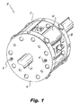
- the vane pump 10 of the subject invention is configured as a cartridge adapted for containment within a sealed enclosure or casing 12.
- Vane pump 10 includes a main pump body 14, a front face plate 16 and a rear face plate 18.
- the front and rear face plates 16 and 18 are secured to the front and rear surfaces of pump body 14 with a plurality of threaded fasteners 15 or the like.
- the front and rear face plates 16 and 18 enclose the interior pumping chamber 20 of pump body 14.
- the pumping chamber 20 defines a central axis and a continuous peripheral cam surface 22.
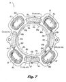
- the configuration or profile of the cam surface 22 establishes the differential sizing of the primary and secondary discharge arc pairs described above, which will be described in far greater detail below with respect to Fig. 7 .
- a cylindrical rotor 24 is mounted for axial rotation within the pumping chamber 20 of pump body 14.
- the rotor 24 has a central bore 25 for receiving a splined drive shaft 27, best seen in Fig. 1 .
- Drive shaft 27 is driven by a prime mover associated with the pump, such as a gas turbine engine.
- a plurality of circumferentially spaced apart radially extending vanes 26 are mounted for radial movement within a corresponding number of circumferentially spaced apart radial vanes slots 28 formed in rotor 24. As best seen in Fig.
- each vane slot 28 has an undervane pocket 28a for receiving pressurized fluid to balance the inwardly directed hydraulic forces exerted at the overvane as the vanes 26 track along the cam surface 22 of pumping chamber 20, as discussed in greater detail below.
- vane pump 10 has an even number of vanes/slots and more preferably vane pump 10 includes sixteen radially extending vanes 26.
- the vanes 26 define an equal number of circumferentially spaced apart pumping buckets or volume chambers 30 which extend between the outer peripheral surface of rotor 24 and the cam surface 22 of pumping chamber 20.
- each bucket 30 receives low pressure fluid delivered into the pumping chamber 20 of pump body 14 as it travels through an inlet arc of the cam surface 22. Conversely, each bucket 30 discharges fluid at a higher pressure as it travels through a discharge arc of the cam surface 22. As each bucket 30 travels from an inlet arc to a discharge arc, it travels through a seal arc of the cam surface 22, wherein the volume of the bucket is reduced and the fluid is discharged from the bucket due to the contracting bucket volume.
- a plurality of circumferentially spaced apart arcuately-shaped magnets 32a-32d surround the pumping chamber 20 of pump body 14. These magnets attract the metallic vanes 26 mounted in rotor 24 and ensure that the radially outer tips of the vanes remain in constant contact with the continuous cam surface 22 of pumping chamber 20 during pump operation. This inhibits leakage between adjacent buckets 30 as the vanes 26 track along the cam surface 22.
- the front and rear face plates 16 and 18 of vane pump 10 each defines a central bore 35 for accommodating passage of the drive shaft 27.
- each face plate defines a plurality of inlet ports that deliver low pressure fluid to a group of intake portals formed in the pump body 14, which communicate directly with the interior pumping chamber 20.
- the front face plate 16 defines the upper inlet port pair 40a, 40a, right inlet port pair 42a, 42b, lower inlet port 44a, 44b and left inlet port pair 46a, 46b.
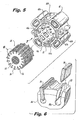
- Corresponding inlet port pairs are also provided in rear face plate 18, including the upper inlet port pair 50a, 50b and right inlet port pair 52a, 52b, lower inlet port pair 54a, 54b and left inlet port pair 56a, 56b, which are illustrated in Fig. 8 .
- the intake portals in pump body 14 that receive fluid from the inlet port pairs of the front and rear side plates 16 and 18 include two upper intake portals 60a, 60b, two right intake portals 62a, 62b, two lower intake portals 64a, 64b, and two left intake portals 66a, 66b, which are best seen in Fig. 5 .
- the pump body 14 further includes a group of discharge portals for directing relatively high pressure fluid from the pumping chamber 20 to a source of fluid demand, such as a gas turbine engine.
- a source of fluid demand such as a gas turbine engine.
- One pair of discharge portals 74a, 74b is illustrated in Fig. 5 , located between intake portals 64a, 64b and intake portals 66a, 66b.
- Discharge portals 70b, 72b, 74b and 76b are also shown in Fig. 8 .
- Each pair of discharge portals in pump body 14 communicate directly with a respective discharge chambers 80a-80d.
- Discharge chambers 80a-80d have front and rear outlets, each surrounded by an elastomeric seal or gasket 82, that communicate with corresponding outlet ports in the front and rear face plates 16 and 18.
- front face plate 16 includes four circumferentially spaced apart outlet ports 90a-90d that communicate with the discharge chambers 80a-80d, respectively.
- a corresponding set of outlet ports 92a-92d are provided in rear face plate 18, as shown for example in Fig. 8 .
- front and rear face plates 16 and 18 each have four circumferentially spaced apart radially extending low pressure fluid conduits.
- front side plate 16 includes radial fluid conduits 102a-102d. These conduits direct low pressure fluid to respective feed ports 104a-104d formed in the interior surface of face plate 16.
- Feed ports 104a-104d are aligned with and feed low pressure fluid to the undervane regions or pockets 28a of the vane slots 28 in rotor 24, as shown for example in Fig. 8 .
- This low pressure fluid provides a balancing pressure below the vanes 26 as they translate radially within the vane slots 28 in regions of low inlet pressure, such as the inlet arcs of cam surface 22.
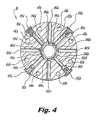
- front and rear face plates 16 and 18 also each include four circumferentially spaced apart radially extending high pressure fluid conduits.
- front side plate 16 includes radial fluid conduits 112a-112d. These conduits, which are enclosed by threaded end caps 115a-115d, direct high pressure fluid to respective arcuate feed slot 114a-114d formed on the interior surface of side plate 16.
- Feed slots 114a-114d are aligned with and feed high pressure fluid to a set of undervane pockets 28a of the vane slots 28 in rotor 24, as shown for example in Fig. 8 .
- This high pressure fuel provides a balancing pressure below the vanes 26 as they translate within the vane slots 28 in regions of high discharge pressure, such as the outlet arcs of cam surface 22.
- the symmetric face plates 16 and 18 of vane pump 10 can be machined, cast or formed by laminating plural plate layers to one another to form the undervane fluid feed passages, ports and slots formed therein. Furthermore, the direct undervane porting through the symmetric fluid conduits of the front and rear face plates 16 and 18 serves to improve vane tracking, reduce the possibility of undervane cavitation that can reduce pump efficiency, and eliminate the parasitic flow losses associated with communicating an intermediate fluid pressure to the undervane pockets, as is often the case in prior art vane pumps employing undervane porting.
- cam surface 22 includes four quadrantal cam segments (i.e., cam segment A-D).
- cam segment A-D quadrantal cam segments
- diametrically opposed cam segments have identical or otherwise symmetrical cam profiles. More particularly, cam segments A and C have identical cam profiles, while cam segments B and D have identical cam profiles.
- each of the four cam segments A-D defines an inlet arc section 122 in which low pressure fluid is received with a pumping bucket 30, a discharge arc section 124 in which fluid is discharged from a pumping bucket 30 at a relatively higher pressure, and two seal arcs sections 126, 128 which fluidly isolate the pumping buckets 30 as they translate from an inlet arc to a discharge arc.
- cam segment A includes inlet arc section 122a, discharge arc section 124a and seal arc sections 126a, 128a;
- cam segment B includes inlet arc section 122b, discharge arc section 124b and seal arc sections 126b, 128b;
- cam segment C includes inlet arc section 122c, discharge arc section 124c and seal arc sections 126c, 128c;
- cam segment D includes inlet arc section 122d, discharge arc section 124d and seal arc sections 126d, 128d.
- a seal arc 126 separates the inlet arc 122 and discharge arc 124 in each cam segment A-D.
- a seal arc 128 also separates the inlet arc 122 in one segment from the discharge arc 124 in a circumferentially adjacent segment.
- the discharge arcs 122a and 122c of diametrically opposed cam segments A and C are equally sized, while the discharge arcs 122a and 122b of circumferentially adjacent cam segments A and B are unequal in size.
- diametrically opposed discharge arcs 122a and 122c may be sized and configured as primary discharge arcs that discharge fluid from the pump at a volumetric rate of 35 gpm, whereas diametrically opposed discharge arcs 122b and 122d may be sized and configured as secondary discharge arcs that discharge fluid from the pump at a relatively lower volumetric rate of 30 gpm.
- axial rotation of drive shaft 27 in a counter-clockwise direction causes corresponding axial rotation of rotor 24 within the pumping chamber 20 of pump body 14.
- low pressure fluid is delivered into the pumping chamber 22 through intake portals 60a,b - 66a,b.
- the low pressure fluid fills the buckets 30 defined by circumferentially adjacent vanes 28 as they translate through the inlet arcs 122a-122d of cam segments A-D.
- each bucket 30 travels from an inlet arc 122a-122d to a discharge arc 124a-124d, it travels through a seal arc 126a-126d, wherein the volume of the bucket 30 is reduced and the fluid within the bucket is compressed, thus increasing its pressure for discharge.
- the higher pressure fluid is discharged from pumping chamber 20 into the four discharge chambers 80a-80d associated with discharge arcs 124a-124d.
- the buckets 30 travel through seal arcs 128a-128d of cam segments A-D to the inlet arcs 122a-122d of cam segments A-D to receive a low pressure fluid once again.
- the undervane pockets 28a of vane slots 28 receive low pressure fluid the low pressure feed ports 104a-104d in face plates 16 and 18, and the undervane pockets 28a of vane slots 28 receive high pressure fluid from arcuate feed slots 114a-114d in face plates 16 and 18, depending upon an angular position of the rotor 24. More particularly, the pressurized fluid in the rotor undervane pockets 28a while they are located in the inlet arc sections 122a-122d of cam segments A-D is relatively low pressure fluid associated with an inlet arc of a cam segment and is equal to pump inlet pressure.
- the pressurized fluid in the rotor undervane pockets 28a while they are located in the discharge arc section 124a-124d of cam segments A-D is relatively high pressure fluid associated with a discharge arc of a cam segment, and is equal to pump discharge pressure.
- the pressurized fluid in the rotor undervane pockets 28a while they are in a seal arc section 126a-126d or 128a-128 of cam segments A-D is relatively high pressure fluid associated with a discharge arc of a cam segment, and is also equal to pump discharge pressure.
- This undervane porting provides a balancing pressure below the vanes 26 to improve vane tip tracking along cam surface 22.
- Fuel metering system 200 includes a split discharge vane pump 10 as described hereinabove which includes a primary pair of diametrically opposed discharge arcs 122a, 122c that are sized and configured to discharge fluid from the pump at a first volumetric flow rate (e.g., 35 gpm) and a secondary pair of diametrically opposed discharge arcs 122b, 122d that are sized and configured to discharge fluid from the pump at a second volumetric flow rate (e.g., 30 gpm).
- a split discharge vane pump 10 as described hereinabove which includes a primary pair of diametrically opposed discharge arcs 122a, 122c that are sized and configured to discharge fluid from the pump at a first volumetric flow rate (e.g., 35 gpm) and a secondary pair of diametrically opposed discharge arcs 122b, 122d that are sized and configured to discharge fluid from the pump at a second volumetric flow rate (e.g., 30 gpm).
- Vane pump 10 receives fluid from a low pressure source at pump inlet pressure PB. Vane pump discharges fluid from the primary pair or discharge arcs 122a, 122c at a primary discharge pressure PF, and it discharges fluid from the secondary pair of discharge arcs 122b, 122d at a secondary discharge pressure P2.
- Fluid metering system 200 further includes a regulator valve 210 in the form of a spool valve or the like which is adapted and configured to control the extraction of pressurized fluid from one or both pairs discharge arcs depending upon the demanded fluid flow condition. More particularly, regulator valve 210 is configured to extract high pressure discharge flow from both the primary pair of discharge arcs 122a, 122c and from the secondary pairs of discharge arcs 122b, 122d under a first demanded fluid flow condition (e.g., at engine start-up) and it is configured to extract high pressure discharge flow from only the primary pair of discharge arcs 122a, 122c under a second demanded fluid flow condition (e.g., at engine idle).
- a first demanded fluid flow condition e.g., at engine start-up
- second demanded fluid flow condition e.g., at engine idle
- Fluid metering system 200 also includes a bypass valve 220 which causes high pressure discharge flow from the secondary pair of discharge arcs 122b, 122d to bypass the source of fluid demand (e.g., a gas turbine engine) and return to the inlet or low pressure side of the pump when regulator valve 210 is operating under the second demanded fluid flow condition.
- Bypass valve 220 and regulator valve 210 communicate with one another through a sensing line that reports the bypass head pressure PBH acting on the valve.
- Fluid metering system 200 also includes a check valve 230 in communication with the source of fluid demand.
- Check valve 230 has a normally closed position that corresponds to the second demanded fluid flow condition wherein fluid from the primary pair of discharge arcs 122a, 122c is permitted to flow to the source of fluid demand.
- check valve 230 has open or actuated position that corresponds to the first demanded fluid flow condition wherein fluid from the primary pair of discharge arcs 122a, 122c and the secondary pair of discharge arcs 122b, 122d is permitted to flow to the source of fluid demand in an additive or cumulative manner.
- Fuel metering system 300 is substantially similar to fuel metering system 200 in that it includes a split discharge vane pump 10 with primary and secondary discharge arc pairs, as described above, a regulator valve 310, a bypass valve 320 and a check valve 330, all in fluid communication with each other in a similar manner.
- Fluid metering system 300 differs from fluid metering system 200 in that it includes an external controller 340 for controlling the pressure differential across the regulator valve 310. It is envisioned that the external controller 340 could take the form of a dual channel torque motor or an electro-hydraulic servo valve (EHSV) or a similar device known in the art. The external controller 340 would be in communication with and receive commands from a Full-Authority Digital Controller (FADEC).
- FADEC Full-Authority Digital Controller
- the invention is directed to disclose a split discharge vane pump having a pump body that includes an interior pumping chamber having a central axis and defining a continuous peripheral cam surface, the cam surface including four quadrantal cam segments, wherein diametrically opposed cam segments have identical cam profiles, and each cam segment defines an inlet arc, a discharge arc and two seal arcs.
- a rotor is mounted for axial rotation within the pumping chamber and a plurality of circumferentially spaced apart radially extending vanes are mounted for radial movement within the rotor, wherein the plurality of vanes define an equal number of circumferentially spaced apart buckets which extend between the rotor and the cam surface of the pumping chamber for carrying pressurized fluid.
Landscapes
- Engineering & Computer Science (AREA)
- Mechanical Engineering (AREA)
- General Engineering & Computer Science (AREA)
- Physics & Mathematics (AREA)
- Fluid Mechanics (AREA)
- Rotary Pumps (AREA)
- Details And Applications Of Rotary Liquid Pumps (AREA)
Applications Claiming Priority (1)
| Application Number | Priority Date | Filing Date | Title |
|---|---|---|---|
| US12/456,086 US8277208B2 (en) | 2009-06-11 | 2009-06-11 | Split discharge vane pump and fluid metering system therefor |
Publications (2)
| Publication Number | Publication Date |
|---|---|
| EP2273122A2 true EP2273122A2 (de) | 2011-01-12 |
| EP2273122A3 EP2273122A3 (de) | 2014-12-03 |
Family
ID=42937257
Family Applications (1)
| Application Number | Title | Priority Date | Filing Date |
|---|---|---|---|
| EP10163593.6A Withdrawn EP2273122A3 (de) | 2009-06-11 | 2010-05-21 | Flügelzellenpumpe mit geteiltem Auslauf und Flüssigkeitsmesssystem dafür |
Country Status (2)
| Country | Link |
|---|---|
| US (2) | US8277208B2 (de) |
| EP (1) | EP2273122A3 (de) |
Cited By (1)
| Publication number | Priority date | Publication date | Assignee | Title |
|---|---|---|---|---|
| EP3269981A4 (de) * | 2015-09-08 | 2018-10-24 | Mikheev, Alexandr Vasilievich | Drehflügelpumpenstator |
Families Citing this family (5)
| Publication number | Priority date | Publication date | Assignee | Title |
|---|---|---|---|---|
| US8277208B2 (en) | 2009-06-11 | 2012-10-02 | Goodrich Pump & Engine Control Systems, Inc. | Split discharge vane pump and fluid metering system therefor |
| US8596991B2 (en) | 2011-02-11 | 2013-12-03 | Triumph Engine Control Systems, Llc | Thermally efficient multiple stage gear pump |
| US20130156564A1 (en) | 2011-12-16 | 2013-06-20 | Goodrich Pump & Engine Control Systems, Inc. | Multi-discharge hydraulic vane pump |
| US9212626B2 (en) * | 2013-07-10 | 2015-12-15 | Derrick T. Miller, Jr. | Engine propulsion system |
| CN103671095B (zh) * | 2013-12-16 | 2016-04-13 | 浙江大学 | 一种多叶片式液压泵 |
Citations (2)
| Publication number | Priority date | Publication date | Assignee | Title |
|---|---|---|---|---|
| US4274817A (en) | 1978-06-06 | 1981-06-23 | Toyota Jidosha Kogyo Kabushiki Kaisha | Rotary vane pump with inlet and discharge ports in end sealing plates |
| US5064363A (en) | 1988-04-06 | 1991-11-12 | Hitachi, Ltd. | Non-lubricated screw machine with a rotor having a taper and varied helical angle |
Family Cites Families (24)
| Publication number | Priority date | Publication date | Assignee | Title |
|---|---|---|---|---|
| US888838A (en) * | 1906-02-28 | 1908-05-26 | Caroline H Mueller | Rotary pump. |
| US2280272A (en) | 1940-05-13 | 1942-04-21 | Citles Service Oil Company | Fluid pump |
| US2256459A (en) * | 1941-02-12 | 1941-09-16 | Manly Corp | Fluid pressure device |
| US2832199A (en) * | 1953-04-30 | 1958-04-29 | American Brake Shoe Co | Vane pump |
| US4047859A (en) * | 1976-08-16 | 1977-09-13 | Chandler Evans Inc | Axial vane pump with non-rotating vanes |
| JPS5669491A (en) * | 1979-11-13 | 1981-06-10 | Kayaba Ind Co Ltd | Vane pump |
| US4516918A (en) * | 1982-05-25 | 1985-05-14 | Trw Inc. | Pump assembly |
| NL8300674A (nl) * | 1983-02-23 | 1984-09-17 | Mullekom Innovation B V Van | Schottenmachine. |
| DE3414535A1 (de) * | 1984-04-17 | 1985-11-07 | Mannesmann Rexroth GmbH, 8770 Lohr | Hydropumpe |
| US4804317A (en) | 1987-03-13 | 1989-02-14 | Eaton Corporation | Rotary vane pump with floating rotor side plates |
| US4963080A (en) * | 1989-02-24 | 1990-10-16 | Vickers, Incorporated | Rotary hydraulic vane machine with cam-urged fluid-biased vanes |
| US5017098A (en) | 1989-03-03 | 1991-05-21 | Vickers, Incorporated | Power transmission |
| DE69000353T2 (de) | 1989-05-24 | 1993-05-06 | Vickers Inc | Fluegelzellenmaschine. |
| US5546018A (en) * | 1993-09-02 | 1996-08-13 | Xilinx, Inc. | Fast carry structure with synchronous input |
| US5545018A (en) | 1995-04-25 | 1996-08-13 | Coltec Industries Inc. | Variable displacement vane pump having floating ring seal |
| GB2345092B (en) | 1998-12-24 | 2002-10-09 | Rolls Royce Plc | Fluid displacement apparatus |
| US6533556B1 (en) | 1999-06-21 | 2003-03-18 | Eric Cozens | Pressure balanced hydraulic pumps |
| US6503064B1 (en) | 1999-07-15 | 2003-01-07 | Lucas Aerospace Power Transmission | Bi-directional low maintenance vane pump |
| US6527525B2 (en) * | 2000-02-08 | 2003-03-04 | Thomas E. Kasmer | Hydristor control means |
| JP2004529283A (ja) | 2000-09-28 | 2004-09-24 | グッドリッチ・パンプ・アンド・エンジン・コントロール・システムズ・インコーポレイテッド | ベーン下方供給装置付きベーンポンプ |
| WO2003044353A1 (en) | 2001-11-15 | 2003-05-30 | Goodrich Pump & Engine Control Systems, Inc. | Method and apparatus for adaptive acceleration schedules in gas turbine engine control systems |
| RU2327900C1 (ru) | 2006-10-30 | 2008-06-27 | Александр Анатольевич Строганов | Роторная шиберная машина |
| US8011909B2 (en) | 2007-03-28 | 2011-09-06 | Goodrich Pump & Engine Control Systems, Inc. | Balanced variable displacement vane pump with floating face seals and biased vane seals |
| US8277208B2 (en) | 2009-06-11 | 2012-10-02 | Goodrich Pump & Engine Control Systems, Inc. | Split discharge vane pump and fluid metering system therefor |
-
2009
- 2009-06-11 US US12/456,086 patent/US8277208B2/en not_active Expired - Fee Related
-
2010
- 2010-05-21 EP EP10163593.6A patent/EP2273122A3/de not_active Withdrawn
-
2012
- 2012-09-04 US US13/602,431 patent/US8807974B2/en not_active Expired - Fee Related
Patent Citations (2)
| Publication number | Priority date | Publication date | Assignee | Title |
|---|---|---|---|---|
| US4274817A (en) | 1978-06-06 | 1981-06-23 | Toyota Jidosha Kogyo Kabushiki Kaisha | Rotary vane pump with inlet and discharge ports in end sealing plates |
| US5064363A (en) | 1988-04-06 | 1991-11-12 | Hitachi, Ltd. | Non-lubricated screw machine with a rotor having a taper and varied helical angle |
Cited By (1)
| Publication number | Priority date | Publication date | Assignee | Title |
|---|---|---|---|---|
| EP3269981A4 (de) * | 2015-09-08 | 2018-10-24 | Mikheev, Alexandr Vasilievich | Drehflügelpumpenstator |
Also Published As
| Publication number | Publication date |
|---|---|
| US8277208B2 (en) | 2012-10-02 |
| US20100316507A1 (en) | 2010-12-16 |
| US20120328463A1 (en) | 2012-12-27 |
| EP2273122A3 (de) | 2014-12-03 |
| US8807974B2 (en) | 2014-08-19 |
Similar Documents
| Publication | Publication Date | Title |
|---|---|---|
| US8807974B2 (en) | Split discharge vane pump and fluid metering system therefor | |
| US8535030B2 (en) | Gerotor hydraulic pump with fluid actuated vanes | |
| CN111379696A (zh) | 在单个壳体中设置有两个泵的泵组件 | |
| US9759103B2 (en) | Lubricant vane pump | |
| JPH03115790A (ja) | ロータリ油圧装置 | |
| EP2464872B1 (de) | Mehrlappige einzelring-flügelzellenpumpe mit druckausgleich und variabler verschiebung | |
| US9765778B2 (en) | Variable displacement rotary pump and displacement regulation method | |
| CN103541898A (zh) | 具有增强的排出口的变排量叶片泵 | |
| EP2878822A1 (de) | Mehrstufige ölpumpe | |
| KR101698914B1 (ko) | 이중 배출 펌프 | |
| EP1208302B1 (de) | Regelbare flügelzellenpumpe mit verstellbaren mantelhäften | |
| US4415319A (en) | Pump unit | |
| CA2712550A1 (en) | Variable-volume internal gear pump | |
| CN103114993B (zh) | 一种阶梯叶片式液压机械 | |
| EP2604790A2 (de) | Hydraulische Flügelpumpe mit mehrfachem Austritt | |
| US9341063B2 (en) | Fluid device with roll pockets alternatingly pressurized at different pressures | |
| WO2010123556A2 (en) | Vane pump with improved rotor and vane extension ring | |
| US5378112A (en) | Positive displacement, variable delivery pumping apparatus | |
| EP3988791A1 (de) | Doppelflügelpumpe mit vordruckerzeugungskanälen | |
| EP2935891B1 (de) | Gleitmittelflügelzellenpumpe | |
| EP0845080A1 (de) | Auslassdruckregelung für eine innenzahnradpumpe | |
| GB2102888A (en) | Rotary positive-displacement pumps | |
| US4163368A (en) | Centrifugal replenishing pump for a hydrostatic pump motor system | |
| EP3872346A1 (de) | Drehflügelpumpe | |
| US20230358228A1 (en) | Rotary vane pump |
Legal Events
| Date | Code | Title | Description |
|---|---|---|---|
| PUAI | Public reference made under article 153(3) epc to a published international application that has entered the european phase |
Free format text: ORIGINAL CODE: 0009012 |
|
| AK | Designated contracting states |
Kind code of ref document: A2 Designated state(s): AL AT BE BG CH CY CZ DE DK EE ES FI FR GB GR HR HU IE IS IT LI LT LU LV MC MK MT NL NO PL PT RO SE SI SK SM TR |
|
| AX | Request for extension of the european patent |
Extension state: BA ME RS |
|
| RAP1 | Party data changed (applicant data changed or rights of an application transferred) |
Owner name: TRIUMPH ENGINE CONTROL SYSTEMS, LLC. |
|
| PUAL | Search report despatched |
Free format text: ORIGINAL CODE: 0009013 |
|
| AK | Designated contracting states |
Kind code of ref document: A3 Designated state(s): AL AT BE BG CH CY CZ DE DK EE ES FI FR GB GR HR HU IE IS IT LI LT LU LV MC MK MT NL NO PL PT RO SE SI SK SM TR |
|
| AX | Request for extension of the european patent |
Extension state: BA ME RS |
|
| RIC1 | Information provided on ipc code assigned before grant |
Ipc: F04C 15/06 20060101ALI20141029BHEP Ipc: F04C 13/00 20060101ALI20141029BHEP Ipc: F04C 14/26 20060101ALI20141029BHEP Ipc: F04C 2/344 20060101AFI20141029BHEP |
|
| 17P | Request for examination filed |
Effective date: 20150525 |
|
| RBV | Designated contracting states (corrected) |
Designated state(s): AL AT BE BG CH CY CZ DE DK EE ES FI FR GB GR HR HU IE IS IT LI LT LU LV MC MK MT NL NO PL PT RO SE SI SK SM TR |
|
| STAA | Information on the status of an ep patent application or granted ep patent |
Free format text: STATUS: EXAMINATION IS IN PROGRESS |
|
| 17Q | First examination report despatched |
Effective date: 20170630 |
|
| STAA | Information on the status of an ep patent application or granted ep patent |
Free format text: STATUS: THE APPLICATION IS DEEMED TO BE WITHDRAWN |
|
| 18D | Application deemed to be withdrawn |
Effective date: 20171111 |