EP2273151A1 - Palier absorbant les chocs pour instruments de précision - Google Patents
Palier absorbant les chocs pour instruments de précision Download PDFInfo
- Publication number
- EP2273151A1 EP2273151A1 EP09405113A EP09405113A EP2273151A1 EP 2273151 A1 EP2273151 A1 EP 2273151A1 EP 09405113 A EP09405113 A EP 09405113A EP 09405113 A EP09405113 A EP 09405113A EP 2273151 A1 EP2273151 A1 EP 2273151A1
- Authority
- EP
- European Patent Office
- Prior art keywords
- bearing
- coupling
- housing
- piece
- clutch
- Prior art date
- Legal status (The legal status is an assumption and is not a legal conclusion. Google has not performed a legal analysis and makes no representation as to the accuracy of the status listed.)
- Withdrawn
Links
- 230000035939 shock Effects 0.000 claims abstract description 24
- 230000008878 coupling Effects 0.000 claims description 149
- 238000010168 coupling process Methods 0.000 claims description 149
- 238000005859 coupling reaction Methods 0.000 claims description 149
- 230000005291 magnetic effect Effects 0.000 claims description 10
- 239000000725 suspension Substances 0.000 description 8
- 238000006073 displacement reaction Methods 0.000 description 6
- 230000005484 gravity Effects 0.000 description 5
- 230000005540 biological transmission Effects 0.000 description 3
- 229920001971 elastomer Polymers 0.000 description 3
- 239000003302 ferromagnetic material Substances 0.000 description 3
- 238000001746 injection moulding Methods 0.000 description 3
- 230000003993 interaction Effects 0.000 description 3
- 235000015095 lager Nutrition 0.000 description 3
- 239000000696 magnetic material Substances 0.000 description 3
- 230000007246 mechanism Effects 0.000 description 3
- 239000004033 plastic Substances 0.000 description 3
- 229920003023 plastic Polymers 0.000 description 3
- 239000004952 Polyamide Substances 0.000 description 2
- 230000001133 acceleration Effects 0.000 description 2
- 239000000919 ceramic Substances 0.000 description 2
- 238000005516 engineering process Methods 0.000 description 2
- 239000000463 material Substances 0.000 description 2
- 229910052751 metal Inorganic materials 0.000 description 2
- 239000002184 metal Substances 0.000 description 2
- 229920002647 polyamide Polymers 0.000 description 2
- 239000005060 rubber Substances 0.000 description 2
- 229910000746 Structural steel Inorganic materials 0.000 description 1
- QJVKUMXDEUEQLH-UHFFFAOYSA-N [B].[Fe].[Nd] Chemical compound [B].[Fe].[Nd] QJVKUMXDEUEQLH-UHFFFAOYSA-N 0.000 description 1
- 229910010293 ceramic material Inorganic materials 0.000 description 1
- 230000008859 change Effects 0.000 description 1
- KPLQYGBQNPPQGA-UHFFFAOYSA-N cobalt samarium Chemical compound [Co].[Sm] KPLQYGBQNPPQGA-UHFFFAOYSA-N 0.000 description 1
- 150000001875 compounds Chemical class 0.000 description 1
- 230000001419 dependent effect Effects 0.000 description 1
- 230000000694 effects Effects 0.000 description 1
- 239000000806 elastomer Substances 0.000 description 1
- 239000002655 kraft paper Substances 0.000 description 1
- 238000004519 manufacturing process Methods 0.000 description 1
- 238000000034 method Methods 0.000 description 1
- 229910000595 mu-metal Inorganic materials 0.000 description 1
- 229910001172 neodymium magnet Inorganic materials 0.000 description 1
- 229910000889 permalloy Inorganic materials 0.000 description 1
- 230000035699 permeability Effects 0.000 description 1
- 239000000843 powder Substances 0.000 description 1
- 230000008569 process Effects 0.000 description 1
- 229910052761 rare earth metal Inorganic materials 0.000 description 1
- 230000000284 resting effect Effects 0.000 description 1
- 229910000938 samarium–cobalt magnet Inorganic materials 0.000 description 1
- 229920002545 silicone oil Polymers 0.000 description 1
- 238000005245 sintering Methods 0.000 description 1
- 125000006850 spacer group Chemical group 0.000 description 1
- 239000013589 supplement Substances 0.000 description 1
- 229920001169 thermoplastic Polymers 0.000 description 1
- 229920001187 thermosetting polymer Polymers 0.000 description 1
- 239000004416 thermosoftening plastic Substances 0.000 description 1
- 239000002023 wood Substances 0.000 description 1
Images


Classifications
-
- F—MECHANICAL ENGINEERING; LIGHTING; HEATING; WEAPONS; BLASTING
- F16—ENGINEERING ELEMENTS AND UNITS; GENERAL MEASURES FOR PRODUCING AND MAINTAINING EFFECTIVE FUNCTIONING OF MACHINES OR INSTALLATIONS; THERMAL INSULATION IN GENERAL
- F16F—SPRINGS; SHOCK-ABSORBERS; MEANS FOR DAMPING VIBRATION
- F16F15/00—Suppression of vibrations in systems; Means or arrangements for avoiding or reducing out-of-balance forces, e.g. due to motion
- F16F15/02—Suppression of vibrations of non-rotating, e.g. reciprocating systems; Suppression of vibrations of rotating systems by use of members not moving with the rotating systems
- F16F15/04—Suppression of vibrations of non-rotating, e.g. reciprocating systems; Suppression of vibrations of rotating systems by use of members not moving with the rotating systems using elastic means
- F16F15/08—Suppression of vibrations of non-rotating, e.g. reciprocating systems; Suppression of vibrations of rotating systems by use of members not moving with the rotating systems using elastic means with rubber springs ; with springs made of rubber and metal
- F16F15/085—Use of both rubber and metal springs
-
- G—PHYSICS
- G04—HOROLOGY
- G04B—MECHANICALLY-DRIVEN CLOCKS OR WATCHES; MECHANICAL PARTS OF CLOCKS OR WATCHES IN GENERAL; TIME PIECES USING THE POSITION OF THE SUN, MOON OR STARS
- G04B37/00—Cases
- G04B37/04—Mounting the clockwork in the case; Shock absorbing mountings
- G04B37/05—Fixed mountings for pocket or wrist watches
- G04B37/055—Fixed mountings for pocket or wrist watches with shock damping means including the winding stem
-
- G—PHYSICS
- G04—HOROLOGY
- G04B—MECHANICALLY-DRIVEN CLOCKS OR WATCHES; MECHANICAL PARTS OF CLOCKS OR WATCHES IN GENERAL; TIME PIECES USING THE POSITION OF THE SUN, MOON OR STARS
- G04B43/00—Protecting clockworks by shields or other means against external influences, e.g. magnetic fields
- G04B43/002—Component shock protection arrangements
Definitions
- the invention relates to the field of storage of precision mechanical instruments, and more particularly to a shock absorbing bearing for precision instruments according to the preamble of claim 1.
- Such a shock-absorbing storage for precision instruments is known for example from the watchmaker by a clockwork is stored in a watch case by means of rubber elements.
- known systems have the disadvantage that the movement of the movements is not sufficiently decoupled from the movement of the housing, so that bumps in certain directions, or bumps that exceed a certain acceleration, are not collected. For example, occur in mechanical watches in certain activities (golf or play tennis, wood chopping, etc.) impulse loads, which damage the movement. Such damage can creep up gradually and increase the clock deviation of the clock over time.
- the resilient arrangement of at least one of bearing body and bearing surface a restoring force back to the rest position.
- the restoring force causes a relative movement between the bearing body and the bearing surface, which leads to the relative position of the bearing body and bearing surface according to the rest position.
- the elastic cushioning of the bearing body can by means of springs, elastomer elements, gas springs, or similar. be realized.
- the materials at the contact points between bearing body and bearing surface are preferably non-elastic (ie metal, ceramic, depending on the application also of a hard plastic such as PAM (polyamide), plastics such as thermosets or thermoplastics) and form a pair of materials, which is a substantially abrasion-free Allow gliding.
- non-elastic ie metal, ceramic, depending on the application also of a hard plastic such as PAM (polyamide), plastics such as thermosets or thermoplastics
- the suspension of the bearing body is such that even with a rotation about the second bearing axis of the bearing body is driven back by the suspension in the rest position.
- This adjusting unit according to the invention is advantageously used together with the bearings described above. It occurs, in a symmetrical arrangement of the bearings, for example, along the circumference of an inner housing, in the place of one of the bearings.
- the actuator is decoupled for normal operation, and happens in this normal operation storage only by means of the bearings described above. Uncoupling is done, for example, by pulling a magnetically held together Kuppung the actuator.
- the actuator is independent of the bearings described here, so realized with other storage devices.
- a rotational axis of the inner piece and an axis of rotation of the outer piece preferably coincide with one another and with the shaft axis, and with the connection between inner piece and outer piece dissolved do not coincide with each other, the axis of rotation of the inner piece and the axis of rotation of the outer piece.
- the inner coupling surface of the inner coupling and the outer coupling surface of the inner coupling in the form of spherical segments.
- the two surfaces are arranged in the rest position concentric with each other and thus allow a mutual rotation about the common center.
- this center is also identical to a center of movement defined by the bearings of the bearing device.
- the inner coupling surface of the outer clutch is formed on an inner coupling element of the outer clutch
- the outer coupling surface of the outer clutch is formed on an outer coupling element of the outer clutch, and are arranged on the two coupling elements, the outer clutch permanent magnets, which a releasable magnetic adhesion between the two Form coupling elements.
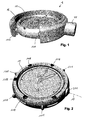
- FIG. 1 shows an overview of the elements of the invention in a preferred embodiment.
- a bearing device 1 an inner housing 11 and an outer housing 12 are arranged to be movable relative to one another.
- This typically carries Inner housing 11 is a shock-sensitive unit 13 and the inner housing 11 is mounted relative to the outer housing 12 and should be protected against shocks that occur on the outer housing 12.
- the shock-sensitive unit 13 is, for example, a clockwork or other fine mechanical device.
- a movement may be used as a separate block in the inner housing 11, or it may be formed on the movement itself, the bearing elements described below, so that therefore the supporting parts of the movement also form the inner housing 11.
- the outer housing 12 surrounds the inner housing ring-like, but is the better representation in the FIG. 1 shown cut.
- FIGS. 2 to 5 show the individual elements of the storage device 1 in different views: At least three locations of the bearing device 1 bearings 14 are arranged, which cooperate for the storage of the inner housing 11.
- FIG. 3 shows this interaction by the inner housing 11 is not shown, but bearing body 111, bearing springs 112 and eccentric 118, which are arranged in or on the inner housing 11, but already.
- bearing body 111 In a sector of the ring-like outer housing 12 whose contour is represented by grid lines dargestell.
- each of the bearings 14 acts on the inner housing 11 elastically movably arranged bearing body 111 with a arranged on the outer housing 12 bearing surface 121 together.
- the bearing body 111 is pressed by means of a bearing spring 112 from the inner housing 11 against the bearing surface 121.
- the shape of the bearing bodies 111 and the bearing surfaces 121 is preferably such that the bearing bodies 111 form a point support on the bearing surfaces 121.
- both the convex bearing body 111 and the concave bearing surfaces 121 are curved, the bearing bodies 111 being curved more strongly than the bearing surfaces 121.
- the bearing bodies 111 have the shape of a spatial ellipsoid on the sides facing the bearing surfaces 121.
- the bearing surfaces 121 are so strongly curved that at a deflection of the inner housing 11 from the rest position by translation or rotation of at least one of the bearing body 111 is pressed against the force of its bearing spring 112 in the inner housing 11. Conversely, then this force drives the inner housing 11 back to the rest position.
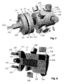
- FIGS. 6 to 9 show the elements of the actuator 2 in different views.
- FIG. 6 shows an overview:
- the actuator 2 has an inner piece 21, an intermediate piece 23 and an outer piece 25.
- the inner piece 21 and intermediate piece 23 are coupled by means of an inner clutch 22 conditionally non-positively to each other.
- the intermediate piece 23 and the outer piece 25 are also conditionally coupled non-positively by means of an external coupling 24.
- "Conditionally non-positively” means that in the respective clutch forces are normally transmitted for displacement and / or rotation, but if the forces exceed a certain level, the clutch disengages and allow mutual movement of the clutch partners according to these forces.
- a central detent body 215 is provided in the inner coupling element 211 of the inner coupling, which attracts the outer coupling element 231 of the inner coupling and improves the transmission of tensile forces.
- the intermediate piece 23 has on an outer coupling element 231 of the inner coupling opposite section on an inner coupling element 236 of the outer coupling. This is formed and formed corresponding to an outer coupling element 256 of the outer coupling.
- an inner coupling surface 237 of the outer clutch of an outer clutch surface 257 of the outer clutch is arranged opposite.
- the inner clutch surface 237 of the outer clutch is rotationally cylindrical, the outer clutch surface 257 of the outer clutch is a correspondingly shaped inner cylinder (not visible in the figures).
- outer clutch magnets 258 of the outer clutch are arranged around the inner circumference of the outer coupling element 256 of the outer clutch.
- the poles of the outer and outer clutch magnets 238, 258 of the outer clutch are aligned in pairs so that they attract each other.
- a rotational movement about the shaft axis 15 as well as a translation along the shaft axis 15 can be transmitted.
- a cylindrical sleeve for example of ceramic material.
- the sleeve may be attached to the inner or outer coupling element.
- an air gap may be present, wherein the bearing then takes place by bearing elements which are not arranged in the region of the magnets.
Landscapes
- Engineering & Computer Science (AREA)
- Physics & Mathematics (AREA)
- General Engineering & Computer Science (AREA)
- General Physics & Mathematics (AREA)
- Chemical & Material Sciences (AREA)
- Combustion & Propulsion (AREA)
- Acoustics & Sound (AREA)
- Aviation & Aerospace Engineering (AREA)
- Mechanical Engineering (AREA)
- Support Of The Bearing (AREA)
Priority Applications (1)
| Application Number | Priority Date | Filing Date | Title |
|---|---|---|---|
| EP09405113A EP2273151A1 (fr) | 2009-07-10 | 2009-07-10 | Palier absorbant les chocs pour instruments de précision |
Applications Claiming Priority (1)
| Application Number | Priority Date | Filing Date | Title |
|---|---|---|---|
| EP09405113A EP2273151A1 (fr) | 2009-07-10 | 2009-07-10 | Palier absorbant les chocs pour instruments de précision |
Publications (1)
| Publication Number | Publication Date |
|---|---|
| EP2273151A1 true EP2273151A1 (fr) | 2011-01-12 |
Family
ID=41328669
Family Applications (1)
| Application Number | Title | Priority Date | Filing Date |
|---|---|---|---|
| EP09405113A Withdrawn EP2273151A1 (fr) | 2009-07-10 | 2009-07-10 | Palier absorbant les chocs pour instruments de précision |
Country Status (1)
| Country | Link |
|---|---|
| EP (1) | EP2273151A1 (fr) |
Citations (3)
| Publication number | Priority date | Publication date | Assignee | Title |
|---|---|---|---|---|
| US2849854A (en) * | 1953-08-19 | 1958-09-02 | Pfisterer Richard | Elastic point-suspension of watch-works in watch-cases |
| US3313101A (en) * | 1965-10-18 | 1967-04-11 | Shirley B Carroll | Instrument case |
| FR1503081A (fr) * | 1965-12-01 | 1967-11-24 | Zentra Markenuhr Gmbh | Montre à montage pare-chocs du mouvement |
-
2009
- 2009-07-10 EP EP09405113A patent/EP2273151A1/fr not_active Withdrawn
Patent Citations (3)
| Publication number | Priority date | Publication date | Assignee | Title |
|---|---|---|---|---|
| US2849854A (en) * | 1953-08-19 | 1958-09-02 | Pfisterer Richard | Elastic point-suspension of watch-works in watch-cases |
| US3313101A (en) * | 1965-10-18 | 1967-04-11 | Shirley B Carroll | Instrument case |
| FR1503081A (fr) * | 1965-12-01 | 1967-11-24 | Zentra Markenuhr Gmbh | Montre à montage pare-chocs du mouvement |
Similar Documents
| Publication | Publication Date | Title |
|---|---|---|
| EP3006894B1 (fr) | Dispositif d'arpentage avec palier à rotule | |
| EP0374611B1 (fr) | Tête de senseur de type commutateur | |
| DE102010027954A1 (de) | Führung mit passiver Schwerkraftkompensation und vertikal beweglich gelagerte Plattform | |
| EP2916450B1 (fr) | Dispositif d'entraînement et procédé pour la génération d'un mouvement guidé, linéaire ou rotatif | |
| EP2486368B1 (fr) | Articulation tournante actionnée magnétiquement et procédé pour faire fonctionner l'articulation | |
| DE102016200491A1 (de) | Mikromechanische Feder für einen Inertialsensor | |
| DE1805789B2 (de) | Nichtlineares federsystem unter verwendung von permanent magneten | |
| EP1754910B1 (fr) | Amortisseur de vibrations avec amortissement dépendant de l'amplitude | |
| EP2273151A1 (fr) | Palier absorbant les chocs pour instruments de précision | |
| EP3676504B1 (fr) | Appareil et chambre vide | |
| EP3528953B1 (fr) | Ensemble piston à aimants permanents muni d'une ossature extérieure logeant des aimants pour un dispositif de piaget | |
| CH663465A5 (de) | Elektromechanischer messkopf. | |
| DE725651C (de) | Elastische Wellenkupplung | |
| EP2848307B1 (fr) | Dispositif de pipetage doté d'une structure d'accouplement pour une seringue pour pipette séparée et doté d'un corps de verrouillage déformable par le champ magnétique destiné à verrouiller et déverrouiller la seringue pour pipette sur la structure d'accouplement | |
| EP2158421B1 (fr) | Soupape de commande et procede pour commuter une soupape de commande | |
| DE102022109267A1 (de) | Tasteinheit und Halterung für eine Tasteinheit | |
| DE102010018493B4 (de) | Koordinatenmessgerät zum Bestimmen von Raumkoordinaten an einem Messobjekt sowie Tastkopf für ein solches Koordinatenmessgerät | |
| WO2008104262A2 (fr) | Dispositif de manipulation et procédé de manipulation pour échantillon biologique | |
| DE102016123696A1 (de) | Anschlagpuffer | |
| EP2804028B1 (fr) | Système d'inversion, endoscope et procédé de montage d'un système optique d'un endoscope | |
| DE19931226C2 (de) | Führungssystem für einen Taster und Tastsystem | |
| DE1805789C (de) | Nichtlineares Federsystem unter Verwendung von Permanentmagneten | |
| DE102010063504A1 (de) | Vorrichtung mit mindestens einer Trägerschicht und zumindest einer an dieser angrenzenden Komponentenschicht | |
| DE2435123A1 (de) | Steuerbarer permanentmagnetischer krafterzeuger | |
| DE202016106816U1 (de) | Anschlagpuffer |
Legal Events
| Date | Code | Title | Description |
|---|---|---|---|
| PUAI | Public reference made under article 153(3) epc to a published international application that has entered the european phase |
Free format text: ORIGINAL CODE: 0009012 |
|
| AK | Designated contracting states |
Kind code of ref document: A1 Designated state(s): AT BE BG CH CY CZ DE DK EE ES FI FR GB GR HR HU IE IS IT LI LT LU LV MC MK MT NL NO PL PT RO SE SI SK SM TR |
|
| AX | Request for extension of the european patent |
Extension state: AL BA RS |
|
| STAA | Information on the status of an ep patent application or granted ep patent |
Free format text: STATUS: THE APPLICATION IS DEEMED TO BE WITHDRAWN |
|
| 18D | Application deemed to be withdrawn |
Effective date: 20110713 |