EP2273210B1 - Boîtier pour un chauffe-eau - Google Patents
Boîtier pour un chauffe-eau Download PDFInfo
- Publication number
- EP2273210B1 EP2273210B1 EP09075273A EP09075273A EP2273210B1 EP 2273210 B1 EP2273210 B1 EP 2273210B1 EP 09075273 A EP09075273 A EP 09075273A EP 09075273 A EP09075273 A EP 09075273A EP 2273210 B1 EP2273210 B1 EP 2273210B1
- Authority
- EP
- European Patent Office
- Prior art keywords
- housing
- labyrinth
- channels
- water
- passages
- Prior art date
- Legal status (The legal status is an assumption and is not a legal conclusion. Google has not performed a legal analysis and makes no representation as to the accuracy of the status listed.)
- Active
Links
Images
Classifications
-
- F—MECHANICAL ENGINEERING; LIGHTING; HEATING; WEAPONS; BLASTING
- F24—HEATING; RANGES; VENTILATING
- F24H—FLUID HEATERS, e.g. WATER OR AIR HEATERS, HAVING HEAT-GENERATING MEANS, e.g. HEAT PUMPS, IN GENERAL
- F24H9/00—Details
- F24H9/02—Casings; Cover lids; Ornamental panels
Definitions
- the invention relates to a housing for a water heater, the housing comprising a housing rear wall and a housing cover, wherein housing rear wall and housing cover each formed by circumferential webs overlap region to form a circumferential sealing surface between housing rear wall and housing cover, and this sealing surface as a labyrinth seal with at least two at different Arranged sides of the housing, the housing interior is formed with the surrounding condensing water condensation openings.
- Such housings serve to provide the instantaneous water heaters, and in particular their mechanical and electronic components, such as e.g. a heater to shield against jet water to the outside.
- a heater to shield against jet water to the outside.
- jet water water acting on the outside of the housing is referred to, which in particular also includes spray water and direct jet water from water sources, such as water. a shower head, involves.
- jet water protection e.g. are documented in the IPX5.
- the housing should be shielded from the environment in such a way that the jet water does not enter the housing interior. This shielding is achieved by appropriate sealing surfaces between the two housing parts.
- condensation can also form within the housing, ie in the interior of the housing, which must be dissipated to the outside.
- the electric water heaters namely the water heater, or their housing have for this purpose in the lower region of the housing at least one condensation water opening, which allows a flow of condensed water from the housing interior.
- Both Housings for water heaters it is now standard to provide multiple mounting options. This concerns in particular a relation to the water connections rotated by 180 ° mounting. In other words, a mounting with downward water connections and with upward water connections is possible. Even a 90 ° rotated assembly with then laterally directed water connections can be guaranteed.
- the DE 36 15 678 A1 also describes a plastic housing of an electric water heater, in which the switch room, so the housing interior is sealed by a labyrinth against water jets. The jet water can collect and drain in the labyrinth.
- Housing with the features of Oberbebriffes of claim 1 are known in the market, in which two condensate openings - for two rotated by 180 ° mounting options - are opposite each other.
- a first known solution provides two opposite, always open condensate in the housing, but not ensure the required jet water protection.
- the respective upper condensate opening - for example, with adhesive tape or the like - is closed.
- Another solution provides such housing, in which the two condensate openings are basically closed. Only the respective lower condensation water opening must be opened before assembly of the housing or the flow heater, namely usually broken out.
- these known housing have the disadvantage that they are either not sufficient protected against jet water, or the implementation of the jet water protection on the one hand unsafe and on the other cumbersome and visually not appealing.
- the preamble of claim 1 is from document DE 43 28 730 known.
- the invention is therefore based on the object to provide a simple to manufacture housing with multiple mounting options that, despite the necessary Kondenswasseröfthungen for all mounting options has a reliable and permanent jet water protection.
- the labyrinth seal has at least one labyrinth channel formed by walls, wherein the or each labyrinth channel has passages for the passage of condensed water, and in the passages and / or in the or each labyrinth channel Barriers are formed against incoming from the environment jet water.
- the barriers arranged or formed within the labyrinth impede the free and uncontrolled flow of the jet water through the labyrinth and, if necessary, selectively divert penetrating jet water through the labyrinth.
- the labyrinth seal has at least two labyrinth channels separated by walls, the labyrinth channels being connected to one another via passages.
- An expedient development of the invention is characterized in that the barriers of material webs and / or material phases are formed integrally with the peripheral web of the rear wall of the housing.
- the passages between the labyrinth channels are formed by recesses in the walls, wherein in the passages material webs are arranged, extending in length over the entire length of the recesses and in height starting from the bottom of the labyrinth channels over part of the wall height extend.
- This design according to the invention reduces the flow / flow of the jet water from labyrinth channel to labyrinth channel.
- the jet water can only flow from labyrinth channel to labyrinth channel from above the height of the material webs in the labyrinth channel.
- the material webs are beveled in the passages to form a material phase, wherein the slope increases in the direction of the housing interior.
- the material phases or directed bevels ensure that penetrating jet water is kept away from the interior of the housing.
- the material phases with the rising towards the housing interior course form an additional obstacle to the jet water.
- a particularly expedient embodiment of the invention is characterized in that material webs arranged transversely to the flow direction of the jet water are arranged within the labyrinth channels. These material webs, which act as a water bulkhead, prevent the streaming / flowing of the jet water within the labyrinth channels in the direction of the interior of the housing and therefore form an additional obstacle.
- the bottom of the labyrinth channels at least partially has a with respect to the flow direction of the jet water in the direction of housing interior gradient.
- the housing shown in the drawing serves to form a protected switching room for water heaters and in particular instantaneous water heater.
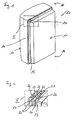
- FIG. 1 such a housing 10 is shown schematically.
- the housing 10 comprises a housing rear wall 11 and a housing cover 12, which in the assembled state form a housing interior or a switching space for receiving the parts forming the instantaneous water heater.
- the housing rear wall 11 has a peripheral web 13, which is preferably formed integrally with the rear wall 11 of the housing.
- the rear wall 11 forms together with the web 13 a trough-like housing part.
- the housing cover 12 also has a peripheral web 14, which is preferably formed integrally with the housing cover 12.
- the housing cover 12 forms together with the web 14 a hood-like housing part.
- the housing parts, which are preferably made of plastic, in the assembled state have an overlapping area for forming a sealing surface 15.
- the sealing surface 15 is formed in the region of the two stacked or nested housing parts or their webs 13, 14.
- the web 14 of the housing cover 12 is outboard.
- the sealing surface 15 is circumferentially formed within the housing 10 as a labyrinth seal 16.
- the labyrinth seal 16 has at least two condensation water openings 17 arranged on different sides of the housing 10. These condensation water openings 17 connect the interior of the housing with the environment, in order to ensure a drainage for possibly resulting condensation.
- In the embodiment shown is at the top 18 of the housing 10 and at the Bottom 19 of the housing 10 each have a condensate opening 17 is formed.
- the assignment top side and bottom side can be changed as desired and does not constitute a fixed allocation.
- condensation water openings 17 may be arranged. The position of the condensation water openings 17 and their number can be different from the embodiment shown.
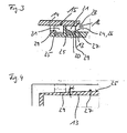
- the labyrinth seal 16 has at least one labyrinth channel 21.
- a housing 10 is shown that has at least two labyrinth channels 21 which are separated from one another by walls 20.
- the number of labyrinth channels 21 may vary and, for example, be three or more.
- the labyrinth channels 21 are preferably formed circumferentially preferably on the web 13. Training on the web 14 is also conceivable.
- the labyrinth channels 21 are associated with the web 13 and each labyrinth channel 21 is guided around the entire housing 10, ie on the upper side 18, the underside 19 and the two sides, as a continuous groove or the like.
- the labyrinth channels 21 may also be interrupted and / or branched and / or merging, in particular in the region of the sides of the housing 10.
- the walls 20 For passage of the condensed water, that is to say for the formation of the condensation water opening 17, the walls 20 have passages 22.
- the adjacent labyrinth channels 21 are connected to one another via passages 22.
- two adjacent labyrinth channels 21 are interconnected by a single passage 22.
- the number of passages 22 in each wall 20 per side, top 18 and bottom 19 may be two or more.
- the passages 22 are each offset from one another.
- a labyrinth channel 21 for example, two passages 22 are formed in the walls 20 forming the labyrinth channel 21 at different positions, ie not lying directly opposite one another. In two or more labyrinth channels 21, the passages 22 are also offset in the labyrinth channels 21 delimiting walls 20 are formed.
- the in the assembled state of the housing 10 and the water heater on the sides and / or the top 18 located condensate openings 17 are inoperative.
- barriers 23 are formed and arranged so as to ensure the drainage of the condensed water as the condensing water opening 17 in the lower mounting position, while preventing the penetration of jet water in the lateral mounting positions or the upper mounting position, but also in the lower mounting position.
- the function of each identically formed condensate openings 17 is dependent on the assembly.
- the labyrinth channels 21 are preferably assigned to the peripheral web 13 of the housing rear wall 11. Corresponding or adapted to the circumferential ridge 14 of the housing cover 12 for covering the labyrinth channels 21 at least in the region of the labyrinth seal 16 inside smooth.
- the smooth formation ensures, in particular in the lower region of the housing 10 or throughflow heater mounted on the wall or the like, that the condensed water guided downwards over the labyrinth channels 21 can flow out of the condensation water openings 17.
- the barriers 23, which are arranged in the region of the passages 22 and / or in the labyrinth channels 21 themselves, are formed of material webs and / or material phases. Preferably, the material webs and material phases are formed integrally with the rear wall 11 of the housing.
- a condensed water opening 17 is formed respectively on the upper side 18 and the lower side 19.
- barriers 23 are arranged.
- the labyrinth channels 21 are designed to be barrier-free on the sides of the housing 10.
- the partitions 20 are formed closed on the sides of the housing 10, so free of Passages 22.
- the design of the labyrinth seal 16 on the sides of the housing 10 is designed differently, in particular, although the sides of the housing 10 have condensation water openings 17.
- the pages can also for other reasons non-continuous, closed labyrinth channels 21, as mentioned above - have.
- the passages 22 between the labyrinth channels 21 are formed by recesses in the walls 20.
- the recesses, openings or the like or their length is small in relation to the length of the walls 20.
- the length is defined in the direction of the course of the walls 20.
- a barrier 23 forming material webs 24 are arranged in the passages 22, arranged.
- the material webs 24 extend in length over the entire length of the recesses, so that accumulating condensate would first have to overcome the material web 24 in order to flow / flow from one labyrinth channel 21 into the adjacent labyrinth channel 21.
- the material webs 24 extend from the base 25 of the labyrinth channels 21 over part of the wall height.
- the material webs 24 may be formed bevelled in the passages 22 and the recesses to form a material phase 26, wherein the slope in the direction of the labyrinth channel 21 further inside, ie in the direction Housing interior, increases.
- the material web 24 may itself be formed entirely and completely as a material phase 26, so that the slope is proceeding directly from the base 25 of the labyrinth channel 21.
- the barriers 23 within the labyrinth channels 21 are preferably material webs 27, which are arranged transversely to the flow direction of the jet water.
- the material webs 27 extend in the labyrinth channels 21 in the width of wall 20 to wall 20. In height, the material webs 27 extend from the base 25 of the labyrinth channels 21 over a portion of the wall height. In other words, the material webs 27 are formed lower than the walls 20.
- the labyrinth channels 21 themselves may have further barriers 23.
- the labyrinth channels 21 at least partially on a rising in the direction of flow of the jet water gradient.
- the Reason 25 of the labyrinth channel 21 continuously sloping is inclined starting from the material web 27 by the angle a relative to the horizontally extending portion to form a material phase 29.
- the material webs 27 extending transversely to the flow direction of the jet water are respectively arranged at the highest point of the rise or the material phase 29, so that the jet water is forced away from the housing interior.
- the walls 20 have in the embodiment shown, viewed from the bottom 25 of all the same height, so that the walls 20 with its upper edge - tolerances possibly only approximately - abut the smooth surface of the housing cover 12.
- the walls 20 may also have a small distance from the housing cover 12.
- the walls 20 may also have different heights.
- the farthest from the housing interior, outer wall 20 is higher than the other walls 20 formed.
- the outermost wall 20 is in this case adapted to rest on a projection 28 formed in the housing cover 12.
- the passages 22 in the walls 20 are preferably formed in the edge regions of the upper side 18 and the lower side 19. The positions of the passages 22 may of course vary.
- the housing 10 is designed such that it is created for different mounting positions.
- the housing 10 or the water heater can be rotated for attachment to a wall or the like.
- the short sides form the upper side 18 and the lower side 19.
- the housing 10 can also be rotated by 90 ° in each case or can even be mounted rotated at any other angle.
- the housing 10 On at least one side, preferably the underside 19, the housing 10 has openings for water connections.
- the housing 10 may also have at the top 18 of the housing and / or on the bottom 19 of the housing 10 corresponding openings.
Landscapes
- Engineering & Computer Science (AREA)
- Physics & Mathematics (AREA)
- Thermal Sciences (AREA)
- Chemical & Material Sciences (AREA)
- Combustion & Propulsion (AREA)
- Mechanical Engineering (AREA)
- General Engineering & Computer Science (AREA)
- Housings, Intake/Discharge, And Installation Of Fluid Heaters (AREA)
- Bidet-Like Cleaning Device And Other Flush Toilet Accessories (AREA)
Claims (12)
- Boîtier pour un chauffe-eau, le boîtier (10) comprenant une paroi arrière de boîtier (11) et un couvercle de boîtier (12), la paroi arrière de boîtier (11) et le couvercle de boîtier (12) comprenant une zone de chevauchement formée respectivement par des parties pont périphériques (13, 14) et destinée à former une surface d'étanchéité périphérique (15) entre la paroi arrière de boîtier (11) et le couvercle de boîtier (12), et cette surface d'étanchéité (15) étant réalisée comme une garniture en labyrinthe (16), caractérisé en ce que la garniture en labyrinthe (16) dotée d'au moins deux ouvertures pour l'eau condensée (17) disposées sur différents côtés du boîtier (10) et reliant l'espace intérieur du boîtier aux zones environnantes comprend au moins un canal de labyrinthe (21) formé par des parois (20), le ou chaque canal de labyrinthe (21) disposant de passages (22) destinés à faire passer l'eau condensée, et des barrières (23) à l'éjection d'eau provenant des zones environnantes étant réalisées dans les passages (22) et/ou dans le et/ou chaque canal de labyrinthe (21).
- Boîtier selon la revendication 1, caractérisé en ce que la garniture de labyrinthe (16) comprend au moins deux canaux de labyrinthe (21) séparés l'un de l'autre par des parois (20), les canaux de labyrinthe (21) étant reliés ensemble par des passages (22).
- Boîtier selon la revendication 1 ou 2, caractérisé en ce que les canaux de labyrinthe (21) sont associés à la partie pont périphérique (13) de la paroi arrière de boîtier (11) et la partie pont (14) du couvercle de boîtier (12) destinée à recouvrir les canaux de labyrinthe (21) est lisse au moins dans la zone de la garniture de labyrinthe (15).
- Boîtier selon l'une quelconque des revendications 1 à 3, caractérisé en ce que les barrières (23) composées de parties pont matérielles (24, 27) et/ou de phases matérielles (26, 29) sont réalisées d'une seule pièce avec la partie pont périphérique (13) de la paroi arrière de boîtier (11).
- Boîtier selon l'une quelconque des revendications 1 à 4, caractérisé en ce que les passages (22) sont formés par des évidements dans les parois (20), des parties pont matérielles (24) s'étendant dans la longueur au-dessus de toute la longueur des évidements et dans la hauteur en partant de la base (25) des canaux de labyrinthe (21) au-dessus d'une partie de la hauteur de la paroi étant disposées dans les passages (22).
- Boîtier selon la revendication 5, caractérisé en ce que les parties pont matérielles (24) dans les passages (22) destinés à former une phase matérielle (26) sont inclinées, l'inclinaison augmentant en direction de l'espace intérieur du boîtier.
- Boîtier selon l'une quelconque des revendications 1 à 6, caractérisé en ce que des parties pont matérielles (27) transversales à la direction d'écoulement du jet d'eau sont disposées à l'intérieur des canaux de labyrinthe (21).
- Boîtier selon la revendication 7, caractérisé en ce que les parties pont matérielles (27) s'étendent dans les canaux de labyrinthe (21) dans la largeur de la paroi (20) à la paroi (20) et dans la hauteur en partant du fond (25) des canaux de labyrinthe (21) au-dessus d'une partie de la hauteur de la paroi.
- Boîtier selon l'une quelconque des revendications 1 à 8, caractérisé en ce que le fond (25) des canaux de labyrinthe (21) présente au moins en partie un tracé croissant dans la direction d'écoulement du jet d'eau.
- Boîtier selon la revendication 9, caractérisé en ce que les parties pont matérielles (27) s'étendant transversalement à la direction d'écoulement du jet d'eau sont disposées respectivement au point le plus haut de l'augmentation à partir du fond (25) des canaux de labyrinthe (21).
- Boîtier selon l'une quelconque des revendications 1 à 10, caractérisé en ce que les parois (20) présentent une hauteur différente de telle sorte que la paroi (20) située à l'extérieur et la plus distante de l'espace intérieur du boîtier soit plus haute que les autres parois (20).
- Boîtier selon l'une quelconque des revendications 1 à 11, caractérisé en ce que les parois (20) sur les côtés du boîtier (10) sont fermées et les canaux de labyrinthe (21) formés de cette façon sont exempts de barrière.
Priority Applications (2)
| Application Number | Priority Date | Filing Date | Title |
|---|---|---|---|
| AT09075273T ATE556279T1 (de) | 2009-06-20 | 2009-06-20 | Gehäuse für ein warmwassergerät |
| EP09075273A EP2273210B1 (fr) | 2009-06-20 | 2009-06-20 | Boîtier pour un chauffe-eau |
Applications Claiming Priority (1)
| Application Number | Priority Date | Filing Date | Title |
|---|---|---|---|
| EP09075273A EP2273210B1 (fr) | 2009-06-20 | 2009-06-20 | Boîtier pour un chauffe-eau |
Publications (2)
| Publication Number | Publication Date |
|---|---|
| EP2273210A1 EP2273210A1 (fr) | 2011-01-12 |
| EP2273210B1 true EP2273210B1 (fr) | 2012-05-02 |
Family
ID=41683494
Family Applications (1)
| Application Number | Title | Priority Date | Filing Date |
|---|---|---|---|
| EP09075273A Active EP2273210B1 (fr) | 2009-06-20 | 2009-06-20 | Boîtier pour un chauffe-eau |
Country Status (2)
| Country | Link |
|---|---|
| EP (1) | EP2273210B1 (fr) |
| AT (1) | ATE556279T1 (fr) |
Families Citing this family (1)
| Publication number | Priority date | Publication date | Assignee | Title |
|---|---|---|---|---|
| DE102017011637A1 (de) * | 2017-12-15 | 2019-06-19 | Stiebel Eltron Gmbh & Co. Kg | Elektrisches Heizgerät mit einem Labyrinth |
Family Cites Families (3)
| Publication number | Priority date | Publication date | Assignee | Title |
|---|---|---|---|---|
| DE3615678A1 (de) | 1986-05-09 | 1987-11-12 | Stiebel Eltron Gmbh & Co Kg | Kunststoffgehaeuse eines elektrischen warmwasserbereiters |
| DE4328730C2 (de) * | 1993-08-26 | 2003-04-03 | Stiebel Eltron Gmbh & Co Kg | Einrichtung zum Verhindern des Wasserdurchtritts |
| DE102006034276B3 (de) | 2006-07-21 | 2008-04-03 | Stiebel Eltron Gmbh & Co. Kg | Warmwasserbereiter |
-
2009
- 2009-06-20 EP EP09075273A patent/EP2273210B1/fr active Active
- 2009-06-20 AT AT09075273T patent/ATE556279T1/de active
Also Published As
| Publication number | Publication date |
|---|---|
| ATE556279T1 (de) | 2012-05-15 |
| EP2273210A1 (fr) | 2011-01-12 |
Similar Documents
| Publication | Publication Date | Title |
|---|---|---|
| EP1939456B1 (fr) | Dispositif de passage d'air | |
| EP3341237B1 (fr) | Station au sol permettant la charge inductive d'un véhicule automobile | |
| DE102006024682A1 (de) | Elektroschrank mit zwei Kühlkanälen | |
| DE102014114900B3 (de) | Kühlluftsystem und Spritzwasser-Schutzanordnung für ein Kühlluftsystem eines Gehäuses und elektrisches oder elektronisches Gerät mit einem Gehäuse | |
| EP3447868B1 (fr) | Canal de câble à points de fixation estampés avec points de rupture prédéterminés et son procédé de fabrication | |
| DE102010033319A1 (de) | Schrankprofil, insbesondere Schaltschrankprofil und Schrank, insbesondere Schaltschrank | |
| DE102010043933A1 (de) | Gehäuse und elektrischer Durchlauferhitzer | |
| EP2418322A2 (fr) | Caniveau de drainage | |
| EP4071317B1 (fr) | Ensemble destiné à la construction d'un garde-corps pourvu de panneaux solaires | |
| EP2132849B1 (fr) | Distributeur souterrain | |
| DE102012220899B4 (de) | Gegen Eindringen von Flüssigkeiten geschütztes Gerätegehäuse | |
| EP2273210A1 (fr) | Boitier pour un chauffe-eau | |
| EP2447620A1 (fr) | Dispositif d'agencement de panneaux solaires et/ou de collecteurs de chaleur sur une base ainsi que système comprenant au moins deux de ces dispositifs | |
| DE102007011386B3 (de) | Wandhängende Mittelspannungs-Schaltanlage | |
| EP1308678B1 (fr) | Dispositif de ventilation | |
| DE10191092B3 (de) | Bausatz für einen Schaltschrank | |
| DE3131223A1 (de) | Ansaug- bzw. abblasegitter | |
| EP2086078B1 (fr) | Boîtier de distribution destiné à l'intégration dans une ouverture murale | |
| DE19513201C1 (de) | Tropfenabscheider für eine dezentrale Heizungs-, Lüftungs- und/oder Kühlvorrichtung | |
| DE29701830U1 (de) | Dispersionseinrichtung für einen Flüssigkeitsverteiler | |
| EP3318436B1 (fr) | Système de toit de véhicule automobile | |
| DE2110089A1 (de) | Explosionsgefährdetes, im wesentlichen einzelliges Gebäude | |
| EP1013844B1 (fr) | Ecoulement d'eau | |
| DE202014101326U1 (de) | Rundsilo mit Belüftungsdach | |
| EP1013843B1 (fr) | Evacuation d'eau à écoulement libre |
Legal Events
| Date | Code | Title | Description |
|---|---|---|---|
| PUAI | Public reference made under article 153(3) epc to a published international application that has entered the european phase |
Free format text: ORIGINAL CODE: 0009012 |
|
| AK | Designated contracting states |
Kind code of ref document: A1 Designated state(s): AT BE BG CH CY CZ DE DK EE ES FI FR GB GR HR HU IE IS IT LI LT LU LV MC MK MT NL NO PL PT RO SE SI SK TR |
|
| AX | Request for extension of the european patent |
Extension state: AL BA RS |
|
| RTI1 | Title (correction) |
Free format text: CASE FOR A WATER HEATER |
|
| 17P | Request for examination filed |
Effective date: 20110621 |
|
| RIC1 | Information provided on ipc code assigned before grant |
Ipc: F24H 9/02 20060101AFI20110721BHEP |
|
| GRAP | Despatch of communication of intention to grant a patent |
Free format text: ORIGINAL CODE: EPIDOSNIGR1 |
|
| GRAS | Grant fee paid |
Free format text: ORIGINAL CODE: EPIDOSNIGR3 |
|
| GRAA | (expected) grant |
Free format text: ORIGINAL CODE: 0009210 |
|
| AK | Designated contracting states |
Kind code of ref document: B1 Designated state(s): AT BE BG CH CY CZ DE DK EE ES FI FR GB GR HR HU IE IS IT LI LT LU LV MC MK MT NL NO PL PT RO SE SI SK TR |
|
| REG | Reference to a national code |
Ref country code: GB Ref legal event code: FG4D Free format text: NOT ENGLISH |
|
| REG | Reference to a national code |
Ref country code: AT Ref legal event code: REF Ref document number: 556279 Country of ref document: AT Kind code of ref document: T Effective date: 20120515 Ref country code: CH Ref legal event code: EP |
|
| REG | Reference to a national code |
Ref country code: IE Ref legal event code: FG4D Free format text: LANGUAGE OF EP DOCUMENT: GERMAN |
|
| REG | Reference to a national code |
Ref country code: DE Ref legal event code: R096 Ref document number: 502009003437 Country of ref document: DE Effective date: 20120628 |
|
| REG | Reference to a national code |
Ref country code: NL Ref legal event code: VDEP Effective date: 20120502 |
|
| REG | Reference to a national code |
Ref country code: LT Ref legal event code: MG4D Effective date: 20120502 |
|
| PG25 | Lapsed in a contracting state [announced via postgrant information from national office to epo] |
Ref country code: LT Free format text: LAPSE BECAUSE OF FAILURE TO SUBMIT A TRANSLATION OF THE DESCRIPTION OR TO PAY THE FEE WITHIN THE PRESCRIBED TIME-LIMIT Effective date: 20120502 Ref country code: NO Free format text: LAPSE BECAUSE OF FAILURE TO SUBMIT A TRANSLATION OF THE DESCRIPTION OR TO PAY THE FEE WITHIN THE PRESCRIBED TIME-LIMIT Effective date: 20120802 Ref country code: CY Free format text: LAPSE BECAUSE OF FAILURE TO SUBMIT A TRANSLATION OF THE DESCRIPTION OR TO PAY THE FEE WITHIN THE PRESCRIBED TIME-LIMIT Effective date: 20120502 Ref country code: FI Free format text: LAPSE BECAUSE OF FAILURE TO SUBMIT A TRANSLATION OF THE DESCRIPTION OR TO PAY THE FEE WITHIN THE PRESCRIBED TIME-LIMIT Effective date: 20120502 Ref country code: SE Free format text: LAPSE BECAUSE OF FAILURE TO SUBMIT A TRANSLATION OF THE DESCRIPTION OR TO PAY THE FEE WITHIN THE PRESCRIBED TIME-LIMIT Effective date: 20120502 Ref country code: IS Free format text: LAPSE BECAUSE OF FAILURE TO SUBMIT A TRANSLATION OF THE DESCRIPTION OR TO PAY THE FEE WITHIN THE PRESCRIBED TIME-LIMIT Effective date: 20120902 Ref country code: PL Free format text: LAPSE BECAUSE OF FAILURE TO SUBMIT A TRANSLATION OF THE DESCRIPTION OR TO PAY THE FEE WITHIN THE PRESCRIBED TIME-LIMIT Effective date: 20120502 |
|
| PG25 | Lapsed in a contracting state [announced via postgrant information from national office to epo] |
Ref country code: PT Free format text: LAPSE BECAUSE OF FAILURE TO SUBMIT A TRANSLATION OF THE DESCRIPTION OR TO PAY THE FEE WITHIN THE PRESCRIBED TIME-LIMIT Effective date: 20120903 Ref country code: SI Free format text: LAPSE BECAUSE OF FAILURE TO SUBMIT A TRANSLATION OF THE DESCRIPTION OR TO PAY THE FEE WITHIN THE PRESCRIBED TIME-LIMIT Effective date: 20120502 Ref country code: HR Free format text: LAPSE BECAUSE OF FAILURE TO SUBMIT A TRANSLATION OF THE DESCRIPTION OR TO PAY THE FEE WITHIN THE PRESCRIBED TIME-LIMIT Effective date: 20120502 Ref country code: LV Free format text: LAPSE BECAUSE OF FAILURE TO SUBMIT A TRANSLATION OF THE DESCRIPTION OR TO PAY THE FEE WITHIN THE PRESCRIBED TIME-LIMIT Effective date: 20120502 Ref country code: GR Free format text: LAPSE BECAUSE OF FAILURE TO SUBMIT A TRANSLATION OF THE DESCRIPTION OR TO PAY THE FEE WITHIN THE PRESCRIBED TIME-LIMIT Effective date: 20120803 |
|
| BERE | Be: lapsed |
Owner name: GERDES OHG Effective date: 20120630 |
|
| PG25 | Lapsed in a contracting state [announced via postgrant information from national office to epo] |
Ref country code: CZ Free format text: LAPSE BECAUSE OF FAILURE TO SUBMIT A TRANSLATION OF THE DESCRIPTION OR TO PAY THE FEE WITHIN THE PRESCRIBED TIME-LIMIT Effective date: 20120502 Ref country code: DK Free format text: LAPSE BECAUSE OF FAILURE TO SUBMIT A TRANSLATION OF THE DESCRIPTION OR TO PAY THE FEE WITHIN THE PRESCRIBED TIME-LIMIT Effective date: 20120502 Ref country code: EE Free format text: LAPSE BECAUSE OF FAILURE TO SUBMIT A TRANSLATION OF THE DESCRIPTION OR TO PAY THE FEE WITHIN THE PRESCRIBED TIME-LIMIT Effective date: 20120502 Ref country code: MC Free format text: LAPSE BECAUSE OF NON-PAYMENT OF DUE FEES Effective date: 20120630 Ref country code: SK Free format text: LAPSE BECAUSE OF FAILURE TO SUBMIT A TRANSLATION OF THE DESCRIPTION OR TO PAY THE FEE WITHIN THE PRESCRIBED TIME-LIMIT Effective date: 20120502 Ref country code: RO Free format text: LAPSE BECAUSE OF FAILURE TO SUBMIT A TRANSLATION OF THE DESCRIPTION OR TO PAY THE FEE WITHIN THE PRESCRIBED TIME-LIMIT Effective date: 20120502 Ref country code: NL Free format text: LAPSE BECAUSE OF FAILURE TO SUBMIT A TRANSLATION OF THE DESCRIPTION OR TO PAY THE FEE WITHIN THE PRESCRIBED TIME-LIMIT Effective date: 20120502 |
|
| PLBI | Opposition filed |
Free format text: ORIGINAL CODE: 0009260 |
|
| PG25 | Lapsed in a contracting state [announced via postgrant information from national office to epo] |
Ref country code: MK Free format text: LAPSE BECAUSE OF FAILURE TO SUBMIT A TRANSLATION OF THE DESCRIPTION OR TO PAY THE FEE WITHIN THE PRESCRIBED TIME-LIMIT Effective date: 20120502 Ref country code: IT Free format text: LAPSE BECAUSE OF FAILURE TO SUBMIT A TRANSLATION OF THE DESCRIPTION OR TO PAY THE FEE WITHIN THE PRESCRIBED TIME-LIMIT Effective date: 20120502 |
|
| PLAX | Notice of opposition and request to file observation + time limit sent |
Free format text: ORIGINAL CODE: EPIDOSNOBS2 |
|
| 26 | Opposition filed |
Opponent name: STIEBEL ELTRON GMBH & CO. KG Effective date: 20130201 |
|
| REG | Reference to a national code |
Ref country code: IE Ref legal event code: MM4A |
|
| REG | Reference to a national code |
Ref country code: FR Ref legal event code: ST Effective date: 20130228 |
|
| PG25 | Lapsed in a contracting state [announced via postgrant information from national office to epo] |
Ref country code: IE Free format text: LAPSE BECAUSE OF NON-PAYMENT OF DUE FEES Effective date: 20120620 Ref country code: BE Free format text: LAPSE BECAUSE OF NON-PAYMENT OF DUE FEES Effective date: 20120630 Ref country code: ES Free format text: LAPSE BECAUSE OF FAILURE TO SUBMIT A TRANSLATION OF THE DESCRIPTION OR TO PAY THE FEE WITHIN THE PRESCRIBED TIME-LIMIT Effective date: 20120813 Ref country code: FR Free format text: LAPSE BECAUSE OF NON-PAYMENT OF DUE FEES Effective date: 20120702 |
|
| REG | Reference to a national code |
Ref country code: DE Ref legal event code: R026 Ref document number: 502009003437 Country of ref document: DE Effective date: 20130201 |
|
| PG25 | Lapsed in a contracting state [announced via postgrant information from national office to epo] |
Ref country code: MT Free format text: LAPSE BECAUSE OF FAILURE TO SUBMIT A TRANSLATION OF THE DESCRIPTION OR TO PAY THE FEE WITHIN THE PRESCRIBED TIME-LIMIT Effective date: 20120502 Ref country code: BG Free format text: LAPSE BECAUSE OF FAILURE TO SUBMIT A TRANSLATION OF THE DESCRIPTION OR TO PAY THE FEE WITHIN THE PRESCRIBED TIME-LIMIT Effective date: 20120802 |
|
| PLAF | Information modified related to communication of a notice of opposition and request to file observations + time limit |
Free format text: ORIGINAL CODE: EPIDOSCOBS2 |
|
| PLBB | Reply of patent proprietor to notice(s) of opposition received |
Free format text: ORIGINAL CODE: EPIDOSNOBS3 |
|
| REG | Reference to a national code |
Ref country code: CH Ref legal event code: PL |
|
| PG25 | Lapsed in a contracting state [announced via postgrant information from national office to epo] |
Ref country code: CH Free format text: LAPSE BECAUSE OF NON-PAYMENT OF DUE FEES Effective date: 20130630 Ref country code: TR Free format text: LAPSE BECAUSE OF FAILURE TO SUBMIT A TRANSLATION OF THE DESCRIPTION OR TO PAY THE FEE WITHIN THE PRESCRIBED TIME-LIMIT Effective date: 20120502 Ref country code: LI Free format text: LAPSE BECAUSE OF NON-PAYMENT OF DUE FEES Effective date: 20130630 |
|
| PG25 | Lapsed in a contracting state [announced via postgrant information from national office to epo] |
Ref country code: LU Free format text: LAPSE BECAUSE OF NON-PAYMENT OF DUE FEES Effective date: 20120620 |
|
| PG25 | Lapsed in a contracting state [announced via postgrant information from national office to epo] |
Ref country code: HU Free format text: LAPSE BECAUSE OF FAILURE TO SUBMIT A TRANSLATION OF THE DESCRIPTION OR TO PAY THE FEE WITHIN THE PRESCRIBED TIME-LIMIT Effective date: 20090620 |
|
| REG | Reference to a national code |
Ref country code: AT Ref legal event code: MM01 Ref document number: 556279 Country of ref document: AT Kind code of ref document: T Effective date: 20140620 |
|
| PLCK | Communication despatched that opposition was rejected |
Free format text: ORIGINAL CODE: EPIDOSNREJ1 |
|
| REG | Reference to a national code |
Ref country code: DE Ref legal event code: R100 Ref document number: 502009003437 Country of ref document: DE |
|
| PLBP | Opposition withdrawn |
Free format text: ORIGINAL CODE: 0009264 |
|
| PLBD | Termination of opposition procedure: decision despatched |
Free format text: ORIGINAL CODE: EPIDOSNOPC1 |
|
| PG25 | Lapsed in a contracting state [announced via postgrant information from national office to epo] |
Ref country code: AT Free format text: LAPSE BECAUSE OF NON-PAYMENT OF DUE FEES Effective date: 20140620 |
|
| PLBN | Opposition rejected |
Free format text: ORIGINAL CODE: 0009273 |
|
| STAA | Information on the status of an ep patent application or granted ep patent |
Free format text: STATUS: OPPOSITION REJECTED |
|
| 27O | Opposition rejected |
Effective date: 20150829 |
|
| PLAU | Termination of opposition procedure: information related to despatch of decision deleted |
Free format text: ORIGINAL CODE: EPIDOSDOPC1 |
|
| REG | Reference to a national code |
Ref country code: DE Ref legal event code: R082 Ref document number: 502009003437 Country of ref document: DE Representative=s name: STORK BAMBERGER PATENTANWAELTE PARTMBB, DE Ref country code: DE Ref legal event code: R081 Ref document number: 502009003437 Country of ref document: DE Owner name: GERDES HOLDING GMBH & CO. KG, DE Free format text: FORMER OWNER: GERDES OHG, 21337 LUENEBURG, DE |
|
| P01 | Opt-out of the competence of the unified patent court (upc) registered |
Effective date: 20230512 |
|
| PGFP | Annual fee paid to national office [announced via postgrant information from national office to epo] |
Ref country code: GB Payment date: 20260604 Year of fee payment: 18 |
|
| PGFP | Annual fee paid to national office [announced via postgrant information from national office to epo] |
Ref country code: DE Payment date: 20260605 Year of fee payment: 18 |