EP2273295A1 - Netzwerkschrankeinpassungssystem - Google Patents
Netzwerkschrankeinpassungssystem Download PDFInfo
- Publication number
- EP2273295A1 EP2273295A1 EP10251194A EP10251194A EP2273295A1 EP 2273295 A1 EP2273295 A1 EP 2273295A1 EP 10251194 A EP10251194 A EP 10251194A EP 10251194 A EP10251194 A EP 10251194A EP 2273295 A1 EP2273295 A1 EP 2273295A1
- Authority
- EP
- European Patent Office
- Prior art keywords
- opening
- fitting
- fitting system
- grommet
- network cabinet
- Prior art date
- Legal status (The legal status is an assumption and is not a legal conclusion. Google has not performed a legal analysis and makes no representation as to the accuracy of the status listed.)
- Withdrawn
Links
Images


Classifications
-
- H—ELECTRICITY
- H02—GENERATION; CONVERSION OR DISTRIBUTION OF ELECTRIC POWER
- H02G—INSTALLATION OF ELECTRIC CABLES OR LINES, OR OF COMBINED OPTICAL AND ELECTRIC CABLES OR LINES
- H02G3/00—Installations of electric cables or lines or protective tubing therefor in or on buildings, equivalent structures or vehicles
- H02G3/02—Details
- H02G3/06—Joints for connecting lengths of protective tubing or channels, to each other or to casings, e.g. to distribution boxes; Ensuring electrical continuity in the joint
- H02G3/0616—Joints for connecting tubing to casing
- H02G3/0691—Fixing tubing to casing by auxiliary means co-operating with indentations of the tubing, e.g. with tubing-convolutions
Definitions
- the present invention relates to a network cabinet fitting system and, more particularly, to a fitting system that is secured to a top opening of a network cabinet for fiber cables passing through a corrugated tube.
- network cabinets have knockouts or removable openings of various sizes to allow cables to enter and exit the cabinet.
- air within the cabinet may escape through the openings and around the cables and adversely affect the cabinet cooling systems.
- the present invention is directed to a fitting system that seals openings in the top of a network cabinet to improve cooling of the network equipment located in the network cabinet.
- the fitting system includes a grommet, a fitting assembly and a filler panel.
- the grommet is secured in one of the openings in the top of the network cabinet.
- the fitting assembly is secured to the grommet.
- the fitting assembly extends partially along the perimeter of the opening in the top of the network cabinet.
- the filler panel seals the remaining opening adjacent to the fitting assembly in the top of the network cabinet. Alternatively, the fitting assembly extends along the entire perimeter of the opening in the top of the network cabinet.
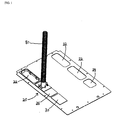
- Fig. 1 is a top perspective view of a network cabinet fitting system according to the present invention
- Fig. 2 is a bottom perspective view of a large cover for the fitting system of Fig. 1 ;
- Fig. 3 is a bottom perspective view of a small cover for the fitting system of Fig. 1 ;
- Fig. 4 is a top perspective view of the fitting system of Fig. 1 , wherein a corrugated tube is not shown;
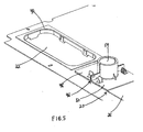
- Fig. 5 is a top perspective view of the fitting system of Fig. 1 , wherein an alternate grommet is installed in the large opening;
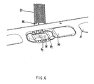
- Fig. 6 is a bottom perspective view of the fitting system of Fig. 1 , wherein a foam insert is installed on a first portion of a corrugated tube fitting assembly;
- Fig. 7 is a top perspective view of the fitting system of Fig. 1 , wherein the corrugated tube is not shown;
- Fig. 8 is a top perspective view of the corrugated tube fitting assembly for the fitting system of Fig. 1 , wherein the fitting assembly is secured to a small grommet;
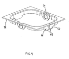
- Fig. 9 is a top perspective view of the small grommet of Fig. 8 ;
- Fig. 10 is a bottom perspective view of a portion of the fitting assembly of Fig. 8 , wherein a foam insert is being installed;
- Fig. 11 is a bottom perspective view of the portion of the fitting assembly of Fig. 8 , wherein the foam insert is installed;
- Fig. 12 is a top perspective view of the portion of the fitting assembly of Fig. 8 , wherein the foam insert is installed;
- Fig. 13 is a top perspective view of a portion of the network cabinet top of Fig. 1 , prior to installation of the fitting system;
- Fig. 14 is a top perspective view of the network cabinet top of Fig. 13 , wherein the large cover has been removed and the corrugated tube has been aligned with the cabinet top opening;
- Fig. 15 is a top perspective view of the network cabinet top of Fig. 14 , wherein the small grommet, filler panel and cables have been installed;
- Fig. 16 is a top perspective view of the network cabinet top of Fig. 15 , wherein the fitting assembly is being secured around the corrugated tube;
- Fig. 17 is a top perspective view of the network cabinet top of Fig. 16 , wherein the fitting assembly has been secured around the corrugated tube;
- Fig. 18 is a top perspective view of the network cabinet top of Fig. 17 , wherein the fitting system has been installed in the cabinet top opening.
- Figs. 1-18 illustrate a fitting system 20 secured to the top of a network cabinet.
- the network cabinet may include various types of servers, switches and other electronic equipment.
- the network cabinet is Panduit Corp.'s Net-AccessTM network cabinet disclosed in U.S. Pat. No. 7,498,512 , the disclosure of which is incorporated by reference in its entirety.
- Fitting system 20 may also be used with other network cabinets.
- the network cabinet includes four large 22 and two small 24 openings for routing power, copper and fiber cables.
- the network cabinet may include any number of large and small openings.
- Figure 1 shows fitting system 20 secured within opening 22, it is likewise contemplated that fitting system 20 may be secured within opening 24. When fitting system 20 is secured within opening 24, filler panel 26 is not necessary.
- Covers 28, 30 are positioned within large 22 and small 24 openings, respectively.
- covers 28, 30 are made from a semi-rigid or flexible material.
- Cover 28 fits in a large opening, such as a 3.5 inch by 8.0 inch opening
- cover 30 fits in a small opening, such as a 3.5 inch by 4.5 inch opening.
- covers 28, 30 include four extended corners 32, 34 to guide covers 28, 30 into openings 22, 24.
- Figs. 4 and 5 illustrate grommet 36 secured within opening 22.
- grommet 36 is used when copper cables are routed into the network cabinet from above and an exhaust duct is not attached to the top of the network cabinet.
- Latches 38 secure grommet 36 within opening 22, and grommet 36 has a slit 40 to allow installation or removal around existing cables.
- grommet 42 may be used.
- fitting system 20 includes grommet 44, corrugated tube fitting assembly 46 and filler panel 26.
- Grommet 44 is secured within opening 22. However, grommet 44 does not extend along the entire perimeter of opening 22. Thus, when fitting assembly 46 is installed in grommet 44, open space remains within opening 22. Filler panel 26 may be used to seal this open space. Alternatively, grommet 44 and fitting assembly 46 may be secured within a small opening, such as opening 24.
- fitting assembly 46 includes first portion 48 and second portion 50.
- first portion 48 and second portion 50 are identical.
- First portion 48 has gripping edge 52, release latches 54 and finger stops 56.
- second portion 50 has gripping edge 58, release latches 60 and finger stops 62.
- the first and second portions may only include latches.
- First portion 48 is secured to second portion 50 to form corrugated tube opening 64, and fitting assembly 46 snaps into grommet 44.
- grommet 44 includes extended lips 66 and chamfered edges 68 to guide grommet 44 into opening 22. Latches 70 secure grommet 44 within opening 22.
- first portion 48 include alignment features, such as tabs 72 and notches 74.
- second portion 50 includes alignment features, such as tabs and notches. The alignment features secure first 48 and second 50 portions around corrugated tube 80.
- first portion 48 has an area of adhesive 82 for securing foam insert 84 to first portion 48.
- Foam insert 84 has slits 86 to improve sealing around cables, and foam insert 84 extends beyond first portion 48 to insure sealing of cables with a pressure fit between first 48 and second 50 portions.
- Figs. 13-18 illustrate the installation of fitting system 20 on the top of the network cabinet.
- cover 28 is removed to expose opening 22 and corrugated tube 80 is aligned with opening 22.
- the top end of corrugated tube 80 is attached to a spillover fitting, and bottom end 88 is cut flush with the surface of opening 22.
- Grommet 44 and filler panel 26 are installed within opening 22. Cables 90 are routed from a cable trough and over a spillover fitting, placed into corrugated tube 80 and passed through grommet 44 into opening 22 (see Fig. 15 ).
- Fig. 15 illustrates the installation of fitting system 20 on the top of the network cabinet.
- first 48 and second 50 portions of fitting assembly 46 are positioned around corrugated tube 80 with bottom end 88 aligned with foam insert 84, and first 48 and second 50 portions are pushed together engaging the alignment features (see Fig. 17 ).
- Foam inserts 84 seal around cables 88, not around corrugated tube 80.
- fitting assembly 46 is pushed downward until fitting assembly 46 snaps into grommet 44.
- a fitting system for sealing an opening in a top of a network cabinet to improve cooling of network equipment, the fitting system comprising: a grommet secured in the opening in the top of the network cabinet; a fitting assembly secured to the grommet, wherein the fitting assembly extends partially along the perimeter of the opening; and a filler panel for sealing the opening adjacent to the fitting assembly.
- the fitting assembly includes a first portion and a second portion secured to each other to form a tube opening.
- first portion and the second portion further comprise alignment features for securing the first portion and the second portion together.
- the first portion and the second portion are identical.
- first portion and the second portion further comprise a foam insert with slits there through for sealing cables passing through the opening.
- first portion and the second portion further comprise release latches and finger stops.
- first portion and the second portion further comprise latches for engaging the grommet secured in the top of the network cabinet.
- the tube opening is positioned around one end of a corrugated tubing for routing cables.
- the fitting assembly includes identical first and second portions, wherein the first and second portions include a horizontal member and a vertical member with a semicircular portion, wherein the semicircular portions join to form a tube opening.
- the first portion and the second portion have gripping edges, wherein the gripping edges are located along an inner wall of the semicircular portions of the first and second portion.
- the grommet further comprises latches for securing the grommet to the network cabinet and extended lips with chamfered edges.
- the filler panel further comprises extended corners for guiding the filler panel into the opening.
- the fitting assembly includes a first portion and a second portion secured to each other to form a tube opening.
- first portion and the second portion further comprise alignment features for securing the first portion and the second portion together.
- the first portion and the second portion are identical.
- first portion and the second portion further comprise a foam insert with slits there through for sealing cables passing through the opening.
- first portion and the second portion further comprise release latches and finger stops.
- first portion and the second portion further comprise latches for securing the fitting assembly to the grommet secured in the top of the network cabinet.
- the tube opening is positioned around one end of the corrugated tube for routing cables.
- the fitting assembly includes identical first and second portions, wherein the first and second portions include a horizontal member and a vertical member with a semicircular portion, wherein the semicircular portions join to form a tube opening.
- the first portion and the second portion have gripping edges, wherein the gripping edges are located along an inner wall of the semicircular portions of the first and second portion.
- the grommet further comprises latches for securing the grommet to the network cabinet and extended lips with chamfered edges.
- a network cabinet having a plurality of openings in a top of the network cabinet and a fitting system secured to the top openings in the network cabinet, the fitting system comprising: a plurality of covers secured within the openings; at least one grommet secured within at least one of the openings; and at least one fitting assembly secured to the grommet.
- the fitting assembly extends along the perimeter of at least one opening.
- the fitting assembly extends partially along the perimeter of at least one opening and the fitting system further comprising a filler panel for sealing an opening adjacent to the fitting assembly.
Landscapes
- Engineering & Computer Science (AREA)
- Architecture (AREA)
- Civil Engineering (AREA)
- Structural Engineering (AREA)
- Insertion, Bundling And Securing Of Wires For Electric Apparatuses (AREA)
- Installation Of Indoor Wiring (AREA)
Applications Claiming Priority (2)
| Application Number | Priority Date | Filing Date | Title |
|---|---|---|---|
| US22312609P | 2009-07-06 | 2009-07-06 | |
| US12/813,056 US20110001408A1 (en) | 2009-07-06 | 2010-06-10 | Network Cabinet Fitting System |
Publications (1)
| Publication Number | Publication Date |
|---|---|
| EP2273295A1 true EP2273295A1 (de) | 2011-01-12 |
Family
ID=43048791
Family Applications (1)
| Application Number | Title | Priority Date | Filing Date |
|---|---|---|---|
| EP10251194A Withdrawn EP2273295A1 (de) | 2009-07-06 | 2010-07-01 | Netzwerkschrankeinpassungssystem |
Country Status (2)
| Country | Link |
|---|---|
| US (1) | US20110001408A1 (de) |
| EP (1) | EP2273295A1 (de) |
Cited By (1)
| Publication number | Priority date | Publication date | Assignee | Title |
|---|---|---|---|---|
| EP3062137A1 (de) * | 2015-02-24 | 2016-08-31 | Draka Comteq B.V. | Verfahren zum verbinden eines faseroptischen kabels an einem verschlusskasten, sowie verbinder und anordnung dafür |
Families Citing this family (14)
| Publication number | Priority date | Publication date | Assignee | Title |
|---|---|---|---|---|
| US8791367B2 (en) * | 2009-10-14 | 2014-07-29 | Panduit Corp. | Network cabinet fitting system |
| CN102343129B (zh) * | 2010-07-30 | 2015-04-01 | 广东松下环境系统有限公司 | 换气扇用的防火闸 |
| US8901438B2 (en) | 2010-09-10 | 2014-12-02 | Chatsworth Products, Inc. | Electronic equipment cabinet structure |
| EP2429272A2 (de) | 2010-09-10 | 2012-03-14 | Chatsworth Products, Inc. | Kabeldurchlaufpaneel für Gehäuse eines elektronischen Geräts |
| US8787023B2 (en) | 2010-09-10 | 2014-07-22 | Chatsworth Products, Inc. | Rail mounting clamp for electronic equipment enclosure |
| CN106029205A (zh) * | 2013-09-18 | 2016-10-12 | 第10街1234有限公司 | 降低燃料的碳排放强度 |
| TWI645812B (zh) * | 2017-10-31 | 2019-01-01 | 川湖科技股份有限公司 | 滑軌機構 |
| US11527877B2 (en) * | 2019-11-25 | 2022-12-13 | Te Connectivity Solutions Gmbh | Electrical element pass through plate constructions |
| US11622458B1 (en) | 2020-12-15 | 2023-04-04 | Chatsworth Products, Inc. | Brush port assembly and method for installing same |
| US12048108B1 (en) | 2020-12-15 | 2024-07-23 | Chatsworth Products, Inc. | Caster attachment system using mating features |
| US11678456B1 (en) | 2020-12-15 | 2023-06-13 | Chatsworth Products, Inc. | Slidable mounting hardware for electronic equipment enclosure and method for installing same |
| US11818860B1 (en) | 2020-12-15 | 2023-11-14 | Chatsworth Products, Inc. | Frame structure for electronic equipment enclosure |
| US11862953B1 (en) * | 2020-12-30 | 2024-01-02 | Titan3 Technology LLC | Electrical outlet cover gasket with bug cover at the cord port |
| US11920392B1 (en) | 2021-02-02 | 2024-03-05 | Chatsworth Products, Inc. | Electrical bonding door hinges |
Citations (8)
| Publication number | Priority date | Publication date | Assignee | Title |
|---|---|---|---|---|
| US4731501A (en) * | 1985-06-19 | 1988-03-15 | Northern Telecom Limited | Entrance terminals for telecommunications cable |
| US4928349A (en) * | 1987-07-15 | 1990-05-29 | Yazaki Corporation | Grommet structure |
| GB2262397A (en) * | 1991-12-03 | 1993-06-16 | Sumitomo Wall Systems Ltd | A grommet |
| DE4326242A1 (de) * | 1993-08-02 | 1995-02-09 | Siemens Ag | Vorrichtung zur abgedichteten Einführung eines Kabels in einen Schaltschrank |
| US6015197A (en) * | 1998-02-28 | 2000-01-18 | 3Com Corp. | Protective grommet apparatus and method |
| DE10027486A1 (de) * | 2000-06-02 | 2001-12-13 | Rapp Wildner Heike | Variables Kabeldurchführungssystem |
| US7498512B2 (en) | 2006-03-13 | 2009-03-03 | Panduit Corp. | Network cabinet |
| WO2009142885A1 (en) * | 2008-05-20 | 2009-11-26 | Panduit Corp. | Cable drop system |
Family Cites Families (30)
| Publication number | Priority date | Publication date | Assignee | Title |
|---|---|---|---|---|
| US4403106A (en) * | 1981-09-21 | 1983-09-06 | Northern Telecom Limited | Terminal enclosure for cable stubs, with variable entry positions |
| US4864080A (en) * | 1987-06-01 | 1989-09-05 | The Carlon Company | Terminator connector fitting for electrical box and conduit system |
| US4814547A (en) * | 1987-10-06 | 1989-03-21 | Cooper Industries, Inc. | Cable connector |
| GB9005744D0 (en) * | 1990-03-14 | 1990-05-09 | Smiths Industries Plc | Fibre-optic entry to an enclosure |
| US5254808A (en) * | 1990-07-11 | 1993-10-19 | Thomas & Betts Corporation | Enclosure for an electrical terminal block including barrier means for a cable entry opening |
| US5101079A (en) * | 1990-07-11 | 1992-03-31 | Thomas & Betts Corporation | Enclosure for an electrical terminal block including barrier means for a cable entry opening |
| US5170008A (en) * | 1991-08-29 | 1992-12-08 | International Business Machines Corp. | External cable grommet for cable entry of EMI protected cabinets |
| GB2274208B (en) * | 1992-12-23 | 1996-07-31 | Elkay Electrical Mgf | Earthed cable gland |
| US5546495A (en) * | 1993-04-16 | 1996-08-13 | The Whitaker Corporation | Splice tray rack and cabinet for fiber optic cables |
| US5696351A (en) * | 1995-03-10 | 1997-12-09 | Ericsson Raynet | Cable retention and sealing device |
| US5732180A (en) * | 1995-06-09 | 1998-03-24 | Multilink, Inc. | Method and apparatus for sealing fiber optic entryways to a sealed enclosure |
| PE69897A1 (es) * | 1996-05-02 | 1997-11-05 | Raychem Sa Nv | Cierre para sellar una abertura |
| FR2763437B1 (fr) * | 1997-05-14 | 1999-08-13 | Legrand Sa | Dispositif d'entree de cable |
| US5969294A (en) * | 1997-12-31 | 1999-10-19 | Siecor Operations, Llc | Fiber optic connector cabinet with rotatably mounted adapter panels |
| US6396990B1 (en) * | 1998-06-12 | 2002-05-28 | Netrix Technologies, Inc. | Multi-purpose communications cabinet |
| US6162989A (en) * | 1998-06-22 | 2000-12-19 | Honeywell Inc | Cable entry shield (EMI-RFI) for electronic units |
| US6044193A (en) * | 1998-07-10 | 2000-03-28 | Siecor Operations, Llc | Fiber optic interconnection enclosure having a forced air system |
| US6248952B1 (en) * | 1999-03-15 | 2001-06-19 | Delphi Technologies, Inc. | Wiring protection dress for automotive electrical wiring extending between a splash shield and tubular conduits |
| JP3620345B2 (ja) * | 1999-05-27 | 2005-02-16 | 住友電装株式会社 | グロメット |
| US6383034B1 (en) * | 2001-02-23 | 2002-05-07 | Corning Cable Systems Llc | Network access terminal |
| WO2003019243A2 (en) * | 2001-05-21 | 2003-03-06 | Wave7 Optics, Inc. | Cable splice enclosure and components |
| US7046521B2 (en) * | 2002-03-13 | 2006-05-16 | Garmong Victor H | Enclosure with shielded power compartment and methods of shielding enclosures |
| US7010210B2 (en) * | 2002-06-21 | 2006-03-07 | Nortel Networks Limited | Entry and internal fiber clips for a fiber management system |
| CA2601473C (en) * | 2005-03-09 | 2012-09-11 | Channell Commercial Corporation | Enclosure system for underground utility connections |
| US7132605B2 (en) * | 2005-04-01 | 2006-11-07 | Adc Telecommunications, Inc. | Split cable seal |
| US7276659B2 (en) * | 2005-05-31 | 2007-10-02 | Hoffman Enclosures, Inc. | Enclosure having a closure member |
| US7266281B1 (en) * | 2005-07-07 | 2007-09-04 | Flatau Joseph G | Optical fiber patch box |
| US7751676B2 (en) * | 2006-11-22 | 2010-07-06 | Alcatel Lucent | Cable entry seal |
| US7496268B2 (en) * | 2006-12-13 | 2009-02-24 | Corning Cable Systems Llc | High density fiber optic hardware |
| US7668431B2 (en) * | 2007-04-10 | 2010-02-23 | Corning Cable Systems Llc | Grommet and plate assembly for sealing fiber optic closures |
-
2010
- 2010-06-10 US US12/813,056 patent/US20110001408A1/en not_active Abandoned
- 2010-07-01 EP EP10251194A patent/EP2273295A1/de not_active Withdrawn
Patent Citations (8)
| Publication number | Priority date | Publication date | Assignee | Title |
|---|---|---|---|---|
| US4731501A (en) * | 1985-06-19 | 1988-03-15 | Northern Telecom Limited | Entrance terminals for telecommunications cable |
| US4928349A (en) * | 1987-07-15 | 1990-05-29 | Yazaki Corporation | Grommet structure |
| GB2262397A (en) * | 1991-12-03 | 1993-06-16 | Sumitomo Wall Systems Ltd | A grommet |
| DE4326242A1 (de) * | 1993-08-02 | 1995-02-09 | Siemens Ag | Vorrichtung zur abgedichteten Einführung eines Kabels in einen Schaltschrank |
| US6015197A (en) * | 1998-02-28 | 2000-01-18 | 3Com Corp. | Protective grommet apparatus and method |
| DE10027486A1 (de) * | 2000-06-02 | 2001-12-13 | Rapp Wildner Heike | Variables Kabeldurchführungssystem |
| US7498512B2 (en) | 2006-03-13 | 2009-03-03 | Panduit Corp. | Network cabinet |
| WO2009142885A1 (en) * | 2008-05-20 | 2009-11-26 | Panduit Corp. | Cable drop system |
Cited By (2)
| Publication number | Priority date | Publication date | Assignee | Title |
|---|---|---|---|---|
| EP3062137A1 (de) * | 2015-02-24 | 2016-08-31 | Draka Comteq B.V. | Verfahren zum verbinden eines faseroptischen kabels an einem verschlusskasten, sowie verbinder und anordnung dafür |
| NL2014340B1 (en) * | 2015-02-24 | 2016-10-13 | Draka Comteq Bv | Method of connecting an optical fiber cable to a closure box, and a connector and assembly therefore. |
Also Published As
| Publication number | Publication date |
|---|---|
| US20110001408A1 (en) | 2011-01-06 |
Similar Documents
| Publication | Publication Date | Title |
|---|---|---|
| EP2273295A1 (de) | Netzwerkschrankeinpassungssystem | |
| US8791367B2 (en) | Network cabinet fitting system | |
| CN109565166B (zh) | 线缆穿壁装置及套件 | |
| US7829797B2 (en) | Three channel raceway | |
| EP2636112B1 (de) | Kabeltülle zur verwendung in einem doppelboden | |
| US7790989B2 (en) | Device and method for universally leading through cables | |
| DE502004001730D1 (de) | Kabeldurchführungsvorrichtung | |
| US7544893B2 (en) | Extruded wire duct end cap | |
| JP2018516062A (ja) | 複数本のケーブル用の壁貫通部を有する構造、その製造方法および組立キット | |
| US8266854B2 (en) | Grommet closure device | |
| JP4866330B2 (ja) | マルチメディアポート用ボックスおよびマルチメディアポート | |
| JP5748432B2 (ja) | ケーブルフィッティングベースのためのカバー | |
| EP2524094A2 (de) | Tüllenschliessvorrichtung | |
| US7673835B2 (en) | Telescoping cover for cable trough system | |
| JP4654099B2 (ja) | 配線配管ダクト装置 | |
| US20150184777A1 (en) | Grommet for Fiber Optic Enclosures | |
| US8445778B2 (en) | Cable entry device for wiring boxes | |
| EP3682514B1 (de) | Erweiterungsrahmen | |
| US20110056722A1 (en) | Wiring Duct Cover With Foam Insert | |
| RU2845624C1 (ru) | Кабеленесущая конструкция | |
| CN101228677B (zh) | 用于电缆线槽系统的转角配件 | |
| DE202025106472U1 (de) | Gehäuse eines Hausautomatisierungsgeräts | |
| EP3671994A1 (de) | Mittel- oder hochspannungsschaltanlage | |
| CZ14062U1 (cs) | Upevnění kanálu, zejména plechového stínícího kanálu, v plastovém elektroinstalačním kanálu | |
| KR20100112331A (ko) | 슬라이드 커버를 구비한 케이블 정리용 하우징 일체형 파워서플라이 유닛 |
Legal Events
| Date | Code | Title | Description |
|---|---|---|---|
| PUAI | Public reference made under article 153(3) epc to a published international application that has entered the european phase |
Free format text: ORIGINAL CODE: 0009012 |
|
| AK | Designated contracting states |
Kind code of ref document: A1 Designated state(s): AL AT BE BG CH CY CZ DE DK EE ES FI FR GB GR HR HU IE IS IT LI LT LU LV MC MK MT NL NO PL PT RO SE SI SK SM TR |
|
| AX | Request for extension of the european patent |
Extension state: BA ME RS |
|
| 17P | Request for examination filed |
Effective date: 20110707 |
|
| RAP1 | Party data changed (applicant data changed or rights of an application transferred) |
Owner name: PANDUIT CORP. |
|
| RIN1 | Information on inventor provided before grant (corrected) |
Inventor name: CAVENEY, JACK E. Inventor name: HARMAN, SCOTT R. |
|
| STAA | Information on the status of an ep patent application or granted ep patent |
Free format text: STATUS: THE APPLICATION HAS BEEN WITHDRAWN |
|
| 18W | Application withdrawn |
Effective date: 20170728 |