EP2273514A2 - In-situ-Magnetiseur und Magnetisierungsverfahren für einen Dauermagnet - Google Patents
In-situ-Magnetiseur und Magnetisierungsverfahren für einen Dauermagnet Download PDFInfo
- Publication number
- EP2273514A2 EP2273514A2 EP10168227A EP10168227A EP2273514A2 EP 2273514 A2 EP2273514 A2 EP 2273514A2 EP 10168227 A EP10168227 A EP 10168227A EP 10168227 A EP10168227 A EP 10168227A EP 2273514 A2 EP2273514 A2 EP 2273514A2
- Authority
- EP
- European Patent Office
- Prior art keywords
- magnetizer
- permanent magnet
- magnetic flux
- rotor
- flux guide
- Prior art date
- Legal status (The legal status is an assumption and is not a legal conclusion. Google has not performed a legal analysis and makes no representation as to the accuracy of the status listed.)
- Withdrawn
Links
- 238000000034 method Methods 0.000 title claims abstract description 27
- 238000011065 in-situ storage Methods 0.000 title claims abstract description 15
- 230000005291 magnetic effect Effects 0.000 claims abstract description 84
- 230000004907 flux Effects 0.000 claims abstract description 73
- 230000005294 ferromagnetic effect Effects 0.000 claims description 10
- 230000005415 magnetization Effects 0.000 description 10
- 238000013459 approach Methods 0.000 description 5
- 238000003475 lamination Methods 0.000 description 3
- 230000009471 action Effects 0.000 description 2
- 238000010276 construction Methods 0.000 description 2
- 230000003993 interaction Effects 0.000 description 2
- 239000000696 magnetic material Substances 0.000 description 2
- 239000002184 metal Substances 0.000 description 2
- 229910052751 metal Inorganic materials 0.000 description 2
- 230000008569 process Effects 0.000 description 2
- RYGMFSIKBFXOCR-UHFFFAOYSA-N Copper Chemical compound [Cu] RYGMFSIKBFXOCR-UHFFFAOYSA-N 0.000 description 1
- 230000004075 alteration Effects 0.000 description 1
- 238000006243 chemical reaction Methods 0.000 description 1
- 239000003302 ferromagnetic material Substances 0.000 description 1
- 238000004519 manufacturing process Methods 0.000 description 1
- 239000000463 material Substances 0.000 description 1
- 230000000135 prohibitive effect Effects 0.000 description 1
- 238000006467 substitution reaction Methods 0.000 description 1
Images


Classifications
-
- H—ELECTRICITY
- H01—ELECTRIC ELEMENTS
- H01F—MAGNETS; INDUCTANCES; TRANSFORMERS; SELECTION OF MATERIALS FOR THEIR MAGNETIC PROPERTIES
- H01F13/00—Apparatus or processes for magnetising or demagnetising
- H01F13/003—Methods and devices for magnetising permanent magnets
-
- H—ELECTRICITY
- H02—GENERATION; CONVERSION OR DISTRIBUTION OF ELECTRIC POWER
- H02K—DYNAMO-ELECTRIC MACHINES
- H02K15/00—Processes or apparatus specially adapted for manufacturing, assembling, maintaining or repairing of dynamo-electric machines
- H02K15/02—Processes or apparatus specially adapted for manufacturing, assembling, maintaining or repairing of dynamo-electric machines of stator or rotor bodies
- H02K15/03—Processes or apparatus specially adapted for manufacturing, assembling, maintaining or repairing of dynamo-electric machines of stator or rotor bodies having permanent magnets
Definitions
- the invention relates generally to the area of magnetizers. More specifically, the invention relates to the area of magnetizers for magnets that are disposed in-situ in a mechanical member, such as a rotor of an interior permanent magnet machine, or a slider of a linear electric machine.
- the rotors of many electric machines include permanent magnets that produce magnetic field flux, which magnetic field flux interacts electromagnetically with a stator.
- the electromagnetic interaction results in a conversion of electromagnetic energy to mechanical energy within the electric machine.
- Interior permanent magnet electric machines constitute a class of electric machines in which the permanent magnets are buried within the bulk of the rotor. In an as-formed state, the permanent magnets do not have any net magnetic moment. However, the design principles of the electric machine require that the permanent magnets disposed within the bulk of the rotor be in a magnetized state before the electric machine can be put in operation.
- a magnetizer that is capable of economically providing user definable magnetic flux field configurations at the locations where the permanent magnets are disposed within the rotor, and having a design that is readily adaptable for electric machines of different sizes and configurations, would therefore be highly desirable.
- Certain embodiments of the invention are directed to a magnetizer capable of magnetizing permanent magnets disposed in-situ a mechanical member.
- mechanical members include, rotors, stators, and sliders.
- a magnetizer includes at least one reconfigurable magnetic flux guide coil.
- the magnetizer may further comprise a magnetizer head may comprising an electromagnet coil and a ferromagnetic member.
- the magnetizer may magnetize substantially completely in substantially a same direction at least one of a plurality of permanent magnets buried within a mechanical member.
- the mechanical member may be selected from the group consisting of a rotor, a stator, and a slider.
- the mechanical member may comprise a backiron of a rotor comprising a plurality of poles.
- the plurality of permanent magnets may be housed within the plurality of poles.
- At least a portion of the at least one reconfigurable magnetic flux guide coil may be disposed along a periphery of any one or more of the plurality of poles.
- the rotor is possibly part of an interior permanent magnet electric machine or of a linear electric machine.
- the rotor may comprise a plurality of laminations stacked oriented along an axial direction of the rotor.
- Each of the plurality of permanent magnets may orient along a substantially radial direction.
- the reconfigurable magnetic flux guide coil may be removably disposed at least partially around any one or more permanent magnet of the plurality of permanent magnets.
- At least a portion of the reconfigurable magnetic flux guide coil may be disposed immediately adjacent to the any one or more permanent magnet of the plurality of permanent magnets.
- Each of the at least one reconfigurable magnetic flux guide coil may comprise at least one conductive member.
- a method of magnetizing a permanent magnet in-situ a mechanical member including the steps of, (a) disposing a first conductive member along a perimeter of the permanent magnet, (b) disposing a second conductive member to mate with the first conductive member to form a magnetic flux guide coil, and (c) energizing the magnetic flux guide coil so that a magnetic field flux is generated within the bulk of the permanent magnet.
- the method may further comprise a step of energizing a magnetizer head comprising an electromagnet coil and a ferromagnetic member.
- the mechanical member may comprise a backiron of a rotor comprising a plurality of poles independently housing one or more of a plurality of permanent magnets.
- At least a portion of the magnetic flux guide coil may dispose along a periphery of any one of the plurality of poles. Individual permanent magnets belonging to the plurality of permanent magnets may orient along a substantially radial direction of the mechanical member. Said steps (a) and (b) may be executed so that at least a portion of the magnetic flux guide coil is disposed around the permanent magnet. At least a portion of the magnetic flux guide coil may be disposed immediately adjacent to the permanent magnet.
- a magnetizer for an interior permanent magnet machine including, at least one reconfigurable magnetic flux guide coil, and a magnetizer head comprising an electromagnet coil and a ferromagnetic member.
- the magnetizer may magnetize at least one of a plurality of permanent magnets buried within a mechanical member.
- the mechanical member may comprise a backiron of a rotor comprising a plurality of poles.
- the plurality of permanent magnets may be housed within the plurality of poles.
- At least a portion of the at least one reconfigurable magnetic flux guide coil may be disposed along a periphery of any one or more of the plurality of poles. Individual permanent magnets belonging to the plurality of permanent magnets may orient along a substantially radial direction of the mechanical member.
- the reconfigurable magnetic flux guide coil may be removably disposed at least partially around any one or more of the permanent magnet of the plurality of permanent magnets. At least a portion of the reconfigurable magnetic flux guide coil may be disposed immediately adjacent to the any one or more permanent magnet of the plurality of permanent magnets.
- embodiments of the invention are directed to magnetizers for permanent magnets in-situ a mechanical member such as a rotor.
- the word "in-situ” refers to the fact that the magnet is positioned within the bulk of the rotor, for instance, within the backiron of the rotor.
- the rotor for instance, may be a part of an electric machine. Quite generally, such machines in which the permanent magnets are positioned within the rotor will be referred to as interior permanent magnet machines.
- Embodiments of the system and method disclosed herein reliably enable magnetization of substantially the complete magnet in substantially the same direction in-situ in a mechanical member.
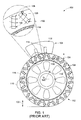
- FIG. 1 is a diagrammatic illustration 100 of a prior art arrangement for magnetizing a rotor 102 using a prior art magnetizer 104.
- the rotor for instance, is part of a permanent magnet electric machine 106 (not depicted).
- the magnetizer 104 is disposed to magnetize one or more of a plurality of permanent magnets 108 disposed within the rotor 102.
- Various configurations for the disposition of the plurality of permanent magnets 108 within the rotor 104 are known in the art. For instance, in the embodiment 102 shown in FIG. 1 , the plurality of permanent magnets are disposed in a "V" shaped configuration 110.
- the magnetizer 104 includes a magnetizer head 112, and coils 114 that form the electromagnetic poles of the magnetizer 104.
- the coils 114 are energized to perform the magnetizing action of the magnetizer 104 whereby a magnetic field flux 130 is produced at least partially within the volumes occupied by the permanent magnets.
- the rotor 102 includes a backiron 116 usually constructed from laminated sheet metal. In the embodiment shown in FIG. 1 , the plurality of permanent magnets 108 are positioned within the bulk of the backiron 116.
- the rotor 102 further includes a rotor tube 118 that is a magnetically inactive carrying structure.
- the rotor 102 also includes further structures 120 the purpose and operation of which would be known to one of skill in the art.
- Electromechanical considerations dictate the thickness 122 of the rotor backiron 116.
- the considerations are related to, for instance, the amount of permanent magnetic material that is required to be contained within the backiron 116, the arrangement of the permanent magnetic material required for a particular operational rating, and the intended application of the permanent magnet electric machine 106.
- Such considerations are known to one of skill in the art.
- Such considerations therefore, dictate the minimum thickness of the backiron 116, which in turn fixes the minimum possible distance scale 124 between the magnetizer 104 and the permanent magnets. The magnetizing action of the permanent magnets must be reliably performed over this distance scale 124.
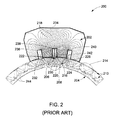
- FIG. 2 is a depiction 200 of a contour plot 202 of a simulated magnetizing field produced via a typical prior art magnetizer of type 104 ( FIG. 1 ).
- the contour plot 202 is shown superimposed onto the schematic depiction of a rotor 204.
- the magnetizer 234 that creates the magnetic field according to contour plot 202 is disposed with respect to the rotor 204 similarly to as shown in FIG. l, that is, externally to the rotor 204, and so that it is substantially symmetrically disposed with respect to the permanent magnets 206 and 208 of the plurality of permanent magnets 210.
- the magnetizer 234 includes, for instance, two coils (not depicted) that are span magnetizer pole cavities 236 and 238, and magnetizer pole cavities 238 and 240.
- the strength of a magnetizing field produced at any spatial location is indicated via a density of contour lines of the contour plot 202.
- the plurality of permanent magnets 210 are disposed in a "V" shaped configuration 214.
- the rotor embodiment 204 may further include other structures 244 which would be known to one of skill in the art.
- the discussions in relation to at least FIGS. 3-4 , and FIGS. 8-9 will be with respect to an assumed representative value of saturation magnetizating magnetic field H Sat of about 1.5 Mega Ampere per meter (MA/m).
- the magnetizing field configuration produced by the magnetizer 234 is now discussed in relation to permanent magnets 208 ( FIG. 3 ), and 216 ( FIG. 4 ), disposed at increasing distance, and oriented differently, with respect to the magnetizer 234.
- contour lines 218 do not flow substantially parallel to the rotor design magnetization direction over the volume occupied by the permanent magnet 208.
- the rotor design magnetization direction is parallel to the short edge of any particular permanent magnet.
- the design magnetization direction is parallel to the short edge 242.
- the direction of the magnetic field produced by the magnetizer 234 is substantially not the same along different regions of the long edge (for instance, 220) of the permanent magnet 208.
- the magnetizing field corresponding to contour lines 230 and 232 would magnetize the corresponding portions of the permanent magnet 208 in differing directions.
- the direction of magnetization resulting due to a magnetizing field, at any particular location, is substantially the direction of the tangent (not shown) to the corresponding contour line.
- two adjacent permanent magnets constitute a pole of the rotor, and rotor design considerations require that the two adjacent permanent magnets constituting a pole of the rotor have opposite magnetizations.
- rotor design considerations require that the magnetization of permanent magnets 206 and 208 be in a first direction, while the magnetization of permanent magnet 216 is required to be in a second direction that is opposite to the first direction.
- FIG. 3 is a graph 300 showing the magnetizing field strength corresponding to the contour plot 202, available along the long edge 220 of the permanent magnet 208.
- the origin 302 of graph 300 corresponds to vertex 222 of the permanent magnet 208.
- the graph 300 then plots the simulated value of magnetizing field strength 304 along the ordinate 306 as a function of the distance from origin along the long edge 220, plotted along the abscissa 308.
- the saturation magnetizing magnetic field H Sat value 310 is also shown. It may be evident that the magnetizing field strength 304 exceeds H Sat only to a distance, from the vertex 222 along the long edge 220, of about 40 millimeters (mm). Evidently therefore, the prior art magnetizer 234 will prove to be inadequate to reliably magnetize the permanent magnet 208 in its entirety.
- FIG. 4 is a graph 400 showing the magnetizing field strength corresponding to the contour plot 202, available along a long edge 224 of the permanent magnet 216.
- the origin 402 of graph 400 corresponds to vertex 226 of the permanent magnet 216.
- the graph 400 then plots the simulated value of magnetizing field strength 404 along the ordinate 406 as a function of the distance from origin along the long edge 224, plotted along the abscissa 408.
- the saturation magnetizing magnetic field H Sat value 410 is also shown. It may be evident that the magnetizing field strength 404 exceeds H Sat only after a distance from the vertex 226 along either of the edges 224 of about 40 mm. Evidently therefore, the prior art magnetizer arrangement will prove to be inadequate to reliably magnetize the permanent magnet 216 in its entirety.
- FIG. 5 is a diagrammatic illustration 500 of a magnetizer arrangement for magnetizing a rotor 502 using a magnetizer 504 in accordance with one embodiment of the invention.
- the rotor 502 for instance, is part of a permanent magnet electric machine 506 (not depicted).
- the magnetizer 504 is positioned to magnetize one or more of a plurality of permanent magnets 508 disposed within the rotor 502.
- the plurality of permanent magnets are disposed in a "V" shaped configuration 510.
- the magnetizer 504 includes a magnetizer head 512, and coils 514 that form the electromagnetic poles of the magnetizer 504.
- the rotor 502 includes a backiron 516 usually constructed from laminated sheet metal. In the rotor embodiment shown in FIG. 5 , the plurality of permanent magnets 508 are positioned within the bulk of the backiron 516.
- the rotor 502 further includes other structures 520, the purpose and operation of which would be known to one of skill in the art.
- the magnetizer 504 further includes at least one reconfigurable magnetic flux guide coil 530, 532.
- the embodiment shown in FIG. 5 includes two reconfigurable magnetic flux guide coils. However, magnetizers of type 504 designed with other numbers of reconfigurable magnetic flux guide coils fall within the scope of the present invention.
- embodiments of the invention include a magnetizer (for instance, of type 504), including at least one reconfigurable magnetic flux guide coil (for instance, of type 530, 532).
- Embodiments of the at least one reconfigurable magnetic flux guide coil includes at least one conductive member.
- the at least one reconfigurable magnetic flux guide coil may include copper wire.
- the at least one reconfigurable magnetic flux guide coil may be removably disposed at least partially around any one or more permanent magnet of the plurality of permanent magnets (for instance, of type 508).
- Energization of the at least one reconfigurable magnetic flux guide coil leads to the creation of a magnetic field flux (not depicted) that flows at least within the loop of the coil, and which magnetic field flux is used to magnetize one or more of the plurality of permanent magnets.
- the reconfigurable magnetic flux guide coils are disposed immediately adjacent to one or more permanent magnets of the plurality of permanent magnets.
- the reconfigurable magnetic flux guide coils are disposed so that portions of the rotor backiron lie between the reconfigurable magnetic flux guide coil and any one or more permanent magnets of the plurality of permanent magnets.
- the magnetizer further include a magnetizer head (for instance, of type 512) including an electromagnet coil (for instance, of type 514) and a ferromagnetic member (for instance, a magnetizer head of type 512 composed from a ferromagnetic material), which ferromagnetic member supports a magnetic field flux produced (not depicted) by the magnetizer.
- a magnetizer head for instance, of type 512
- an electromagnet coil for instance, of type 514
- a ferromagnetic member for instance, a magnetizer head of type 512 composed from a ferromagnetic material
- at least a portion of the at least one reconfigurable magnetic flux guide coil is disposed along a periphery 540 of any one or more of a plurality of poles 542.
- any individual permanent magnet of the plurality of permanent magnets 508 sits within a rotor pole cavity, that is, within one of the poles of the plurality of poles 542, within the rotor backiron 516.
- the permanent magnet 526 sits within a rotor pole cavity 528.
- the rotor cavity can be designed and constructed so that, in addition to housing a permanent magnet, room remains within it to accommodate additional members such as reconfigurable magnetic flux guide coils.
- a pair of reconfigurable magnetic flux guide coils 530 and 532 are accommodated substantially within portions 534 and 536 of rotor pole cavities 528 and 538.
- the reconfigurable magnetic flux guide coils are disposed so that they removably wrap around any particular permanent magnet.
- FIG. 6 diagrammatically illustrates how a reconfigurable magnetic flux guide coil 602 wraps around a permanent magnet 604 that is disposed within a rotor backiron (for instance, of type 516; not shown).
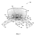
- FIG. 7 is a depiction 700 of a contour plot 702 of simulated magnetizing field produced via a magnetizer 704 of type 504 ( FIG. 5 ).
- the magnetizer 704 In the interest of clarity, only certain components of the magnetizer 704 are depicted, as discussed below. In particular, only reconfigurable magnetic flux guide coils 714 and 716, of the magnetizer 704 disposed respectively around permanent magnets 708 and 710, are shown. Furthermore, the magnetizer head 720, which is of type 512, is not shown.
- the contour plot 702 is shown superimposed onto the schematic depiction of a rotor 706 of type 502 ( FIG. 5 ).
- the magnetizer 704 that created the magnetic field according to contour plot 702 is disposed with respect to the rotor 706 similarly to as shown in FIG. 5 , that is, externally to the rotor 706, and so that it is substantially symmetrically disposed with respect to permanent magnets 708 and 710 of the plurality of permanent magnets 712.
- the strength of magnetizing field produced at any spatial location is indicated via the density of the contour lines of the contour plot 702.
- the plurality of permanent magnets 712 are disposed in a "V" shaped configuration 722.
- the magnetizing field configuration produced by the magnetizer 704 is now discussed in relation to permanent magnets 710 ( FIG. 8 ), and 724 ( FIG. 9 ), disposed at increasing distance, and oriented differently, with respect to the magnetizer 704.
- contour lines 728 flow substantially parallel to each other and to the design magnetization direction.
- the design magnetization direction is substantially parallel to the short edge of any particular permanent magnet, and indicated by arrows 752, 754, 756, and 758.
- the direction of the magnetizing field produced by the magnetizer 704 is substantially the same along the body of the permanent magnet.
- the magnetizing field corresponding to contour lines 730 and 732 would magnetize the corresponding portion of the permanent magnet 708 in substantially the same direction.
- a rotor magnetized according to the scheme shown in FIG. 7 is likely to transmit more power as compared to a rotor magnetized according to the scheme shown in FIG. 5 .
- magnetizers are capable of magnetizing substantially completely in substantially a same direction at least one of a plurality of permanent magnets buried within a mechanical member.
- a mechanical member include a backiron 742 of a rotor (for instance, of type 706) comprising a plurality of poles 744.
- the plurality of permanent magnets 712 are housed within the plurality of poles 744.
- the plurality of permanent magnets are oriented along a substantially radial direction 750.
- the rotor is part of an interior permanent magnet electric machine (not depicted), or of a linear electric machine (not depicted).
- the rotor includes a plurality of laminations stacked so as to be oriented along an axial direction 748 of the rotor.
- Principles of design and construction of rotors are well known in the art.
- FIG. 8 is a graph 800 showing the magnetizing field strength corresponding to the contour plot 702, available along a long edge 734 of the permanent magnet 710.
- the origin 802 of graph 800 corresponds to vertex 736 of the permanent magnet 710.
- the graph 800 then plots the simulated value of magnetizing field strength 804 along the ordinate 806 as a function of the distance from origin 802 along the long edge 734, plotted along the abscissa 808.
- the saturation magnetizing magnetic field H Sat value 810 is also shown. It may be evident that the magnetizing field strength 804 exceeds H Sat along the entire length of the permanent magnet 710. Evidently therefore, the magnetizer 704 arrangement will prove to be adequate to reliably magnetize the permanent magnet 710 in its entirety.
- FIG. 9 is a graph 900 showing the magnetizing field strength corresponding to the contour plot 702, available along either of a long edge 738 of the permanent magnet 724.
- the origin 902 of graph 900 corresponds to vertex 740 of the permanent magnet 724.
- the graph 900 then plots the simulated value of magnetizing field strength 904 along the ordinate 906 as a function of the distance from origin 902 along either the long edge 738, plotted along the abscissa 908.
- the saturation magnetizing magnetic field H Sat value 910 is also shown. It may be evident that the magnetizing field strength 904 exceeds H Sat uptil a distance from the vertex 740 along the long edge 738 of about 35 mm.
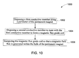
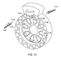
- FIG. 10 is a flow chart depiction of a method 1000 of magnetizing a permanent magnet in-situ within a mechanical member in accordance with one embodiment of the invention.
- the method 1000 includes a step 1002 of disposing a first conductive member along a perimeter or periphery (for instance, of type 540) of the permanent magnet (for instance, of type 708).
- An embodiment of step 1002 is graphically illustrated via FIG. 11 , whereby a first conductive member 1102 is inserted into portions 1104 (for instance, of type 534) of rotor pole cavity 1108 (for instance, of type 528).
- the method 1000 also includes a step 1004 of disposing a second conductive member to mate with the first conductive member 1102 to form a magnetic flux guide coil.
- step 1004 is graphically illustrated via FIG. 11 .
- a second conductive member 1112 is disposed to mate with the ends 1114 and 1116 of the first conductive member 1102 to form a reconfigurable magnetic flux guide coil (for instance, of type 530).
- steps 1002 and 1004 may be executed so that at least a portion of the magnetic flux guide coil is disposed around the permanent magnet 1120.
- at least a portion of the magnetic flux guide coil may be disposed along a periphery of any one of the plurality of poles 1122.
- the method 1000 also includes a step 1006 of energizing the magnetic flux guide coil so that a magnetic field flux is generated within the bulk of the permanent magnet.
- an electric current is passed through the reconfigurable magnetic flux guide coil to energize it, which in turn leads to the creation of a magnetic field (in accordance with well known physical principles; not depicted) within the volume occupied by the permanent magnet 1120 (for instance, of type 604).
Landscapes
- Engineering & Computer Science (AREA)
- Power Engineering (AREA)
- Manufacturing & Machinery (AREA)
- Permanent Field Magnets Of Synchronous Machinery (AREA)
- Hard Magnetic Materials (AREA)
Applications Claiming Priority (1)
| Application Number | Priority Date | Filing Date | Title |
|---|---|---|---|
| US12/499,823 US8766753B2 (en) | 2009-07-09 | 2009-07-09 | In-situ magnetizer |
Publications (2)
| Publication Number | Publication Date |
|---|---|
| EP2273514A2 true EP2273514A2 (de) | 2011-01-12 |
| EP2273514A3 EP2273514A3 (de) | 2014-01-15 |
Family
ID=42942269
Family Applications (1)
| Application Number | Title | Priority Date | Filing Date |
|---|---|---|---|
| EP10168227.6A Withdrawn EP2273514A3 (de) | 2009-07-09 | 2010-07-02 | In-situ-Magnetiseur und Magnetisierungsverfahren für einen Dauermagnet |
Country Status (3)
| Country | Link |
|---|---|
| US (1) | US8766753B2 (de) |
| EP (1) | EP2273514A3 (de) |
| CN (1) | CN101958174B (de) |
Families Citing this family (8)
| Publication number | Priority date | Publication date | Assignee | Title |
|---|---|---|---|---|
| IT1395148B1 (it) * | 2009-08-07 | 2012-09-05 | Rolic Invest Sarl | Metodo e apparecchiatura di attivazione di una macchina elettrica e macchina elettrica |
| US8362863B2 (en) | 2011-01-14 | 2013-01-29 | General Electric Company | System and method for magnetization of rare-earth permanent magnets |
| JP2013223403A (ja) * | 2012-04-19 | 2013-10-28 | Fanuc Ltd | 連続スキュー構造を有するロータの着磁ヨーク、及び該ロータの製造方法 |
| JP2013229986A (ja) * | 2012-04-25 | 2013-11-07 | Fanuc Ltd | 段スキューされたロータに着磁するための着磁装置及びそのような着磁装置を利用する電動機用ロータの製造方法 |
| JP6192400B2 (ja) * | 2013-07-10 | 2017-09-06 | 住友重機械工業株式会社 | 永久磁石電動機およびその着磁方法 |
| BR102015020792A2 (pt) * | 2015-08-27 | 2017-03-01 | Whirlpool Sa | dispositivo e processo para magnetização de rotor de motor elétrico |
| EP4085517A4 (de) | 2019-12-31 | 2024-05-01 | Baker Hughes Oilfield Operations, LLC | Systeme und verfahren zum magnetisieren von permanentmagnetrotoren |
| JP2023144536A (ja) * | 2022-03-28 | 2023-10-11 | 本田技研工業株式会社 | 着磁方法及び着磁装置 |
Citations (1)
| Publication number | Priority date | Publication date | Assignee | Title |
|---|---|---|---|---|
| US20030209950A1 (en) * | 2002-05-07 | 2003-11-13 | Biais Francois J. | Auxiliary magnetizing winding for interior permanent magnet rotor magnetization |
Family Cites Families (15)
| Publication number | Priority date | Publication date | Assignee | Title |
|---|---|---|---|---|
| US4390815A (en) | 1981-03-17 | 1983-06-28 | Rca Corporation | Apparatus for influencing electron beam movement |
| JPH0789728B2 (ja) * | 1985-04-30 | 1995-09-27 | 三菱化学株式会社 | モ−タ |
| JPS63316658A (ja) | 1987-06-19 | 1988-12-23 | Seiko Epson Corp | 多極着磁の方法 |
| JP3671621B2 (ja) | 1997-09-30 | 2005-07-13 | いすゞ自動車株式会社 | 永久磁石式渦電流減速装置の着磁方法 |
| GB0005744D0 (en) * | 2000-03-10 | 2000-05-03 | Federal Mogul Ignition Uk Ltd | Fuel injector |
| US6441521B1 (en) | 2000-05-12 | 2002-08-27 | Reliance Electric Technologies, Llc | Hybrid superconducting motor/generator |
| JP3474152B2 (ja) * | 2000-08-10 | 2003-12-08 | 三菱電機株式会社 | 永久磁石回転子の着磁装置 |
| DE10049766A1 (de) | 2000-09-29 | 2002-04-11 | Siemens Ag | Verfahren und Anordnung zum Magnetisieren von Magnetsystemen |
| DE60121989T2 (de) | 2000-11-15 | 2007-02-01 | Hirst Magnetic Instruments Ltd., Falmouth | Verfahren und vorrichtung zur magnetisierung mehrerer benachbarten abschnitte eines magnetisierbaren materials |
| US6684483B2 (en) | 2001-09-14 | 2004-02-03 | General Motors Corporation | Method of fabricating a rotor for an electric traction motor |
| US7148598B2 (en) | 2003-10-23 | 2006-12-12 | A.O. Smith Corporation | Spoke permanent magnet rotors for electrical machines and methods of manufacturing same |
| DE102004017157B4 (de) | 2004-04-07 | 2007-04-19 | Minebea Co., Ltd. | Verfahren zur Herstellung einer Rotoranordnung und Rotoranordnung für eine elektrische Maschine |
| US7479723B2 (en) | 2007-01-30 | 2009-01-20 | Gm Global Technology Operations, Inc. | Permanent magnet machine rotor |
| EP2299112B1 (de) | 2007-03-23 | 2015-05-13 | Vestas Wind Systems A/S | Verfahren zur Herstellung eines Windturbinengenerators mit einem oder mehreren Permanentmagnetrotoren, Windturbinengondel und Windturbine |
| US20090009012A1 (en) * | 2007-07-03 | 2009-01-08 | General Electric Company | Assembly and method for magnetization of permanent magnet rotors in electrical machines |
-
2009
- 2009-07-09 US US12/499,823 patent/US8766753B2/en not_active Expired - Fee Related
-
2010
- 2010-07-02 EP EP10168227.6A patent/EP2273514A3/de not_active Withdrawn
- 2010-07-09 CN CN201010231158.1A patent/CN101958174B/zh not_active Expired - Fee Related
Patent Citations (1)
| Publication number | Priority date | Publication date | Assignee | Title |
|---|---|---|---|---|
| US20030209950A1 (en) * | 2002-05-07 | 2003-11-13 | Biais Francois J. | Auxiliary magnetizing winding for interior permanent magnet rotor magnetization |
Also Published As
| Publication number | Publication date |
|---|---|
| CN101958174A (zh) | 2011-01-26 |
| EP2273514A3 (de) | 2014-01-15 |
| US8766753B2 (en) | 2014-07-01 |
| US20110006865A1 (en) | 2011-01-13 |
| CN101958174B (zh) | 2015-01-28 |
Similar Documents
| Publication | Publication Date | Title |
|---|---|---|
| US8766753B2 (en) | In-situ magnetizer | |
| US7915777B2 (en) | Ring coil motor | |
| EP2490319B1 (de) | Motor mit axialspalt | |
| US7061152B2 (en) | Rotor-stator structure for electrodynamic machines | |
| CN101997344B (zh) | 超导磁化器 | |
| US10236730B2 (en) | Electric machine with low magnetic slot leakage | |
| US20060103254A1 (en) | Permanent magnet rotor | |
| US20150097458A1 (en) | Permanent Magnet Electric Machine | |
| EP1786085A3 (de) | Rotierende elektrische Maschine mit Permanentmagneten | |
| US9583997B2 (en) | Magnetizer and assembler for electrical machines | |
| JP2010193587A (ja) | ロータ用磁石着磁装置およびモータ | |
| WO2012089217A3 (en) | Magnetizer for electrical machines | |
| US11831210B2 (en) | Non-cogging high efficiency electric generator | |
| JP2013223417A (ja) | 固定式永久磁石発電機 | |
| US20100133942A1 (en) | Permanent Magnet Arrangement for Generator Rotor | |
| US9608483B2 (en) | Electrical machine with magnetic flux intensifier | |
| Wu et al. | Optimization design and research of a hybrid excitation compulsator | |
| CN105075069B (zh) | 用于电机的转动部件 | |
| WO2011066996A3 (de) | Mit permanentmagneten erregte elektrische maschine | |
| Lv et al. | Design and experiment of surface-mounted permanent-magnet motors with integrated magnetizing windings | |
| RU116714U1 (ru) | Магнитоэлектрическая дисковая машина | |
| JP2008312427A5 (de) | ||
| Schofield et al. | The application of soft magnetic composites to the design of tubular linear actuators | |
| Damanik et al. | Investigation on Different Permanent Magnet Configuration in 12 Slot 8 Pole of Permanent Magnet Synchronous Generator | |
| KR20160021857A (ko) | 회전 자기장 기기에 대한 개선 방법 |
Legal Events
| Date | Code | Title | Description |
|---|---|---|---|
| PUAI | Public reference made under article 153(3) epc to a published international application that has entered the european phase |
Free format text: ORIGINAL CODE: 0009012 |
|
| AK | Designated contracting states |
Kind code of ref document: A2 Designated state(s): AL AT BE BG CH CY CZ DE DK EE ES FI FR GB GR HR HU IE IS IT LI LT LU LV MC MK MT NL NO PL PT RO SE SI SK SM TR |
|
| AX | Request for extension of the european patent |
Extension state: BA ME RS |
|
| RIC1 | Information provided on ipc code assigned before grant |
Ipc: H01F 13/00 20060101AFI20130912BHEP Ipc: H02K 15/03 20060101ALI20130912BHEP |
|
| PUAL | Search report despatched |
Free format text: ORIGINAL CODE: 0009013 |
|
| AK | Designated contracting states |
Kind code of ref document: A3 Designated state(s): AL AT BE BG CH CY CZ DE DK EE ES FI FR GB GR HR HU IE IS IT LI LT LU LV MC MK MT NL NO PL PT RO SE SI SK SM TR |
|
| AX | Request for extension of the european patent |
Extension state: BA ME RS |
|
| RIC1 | Information provided on ipc code assigned before grant |
Ipc: H01F 13/00 20060101AFI20131212BHEP Ipc: H02K 15/03 20060101ALI20131212BHEP |
|
| 17P | Request for examination filed |
Effective date: 20140715 |
|
| RBV | Designated contracting states (corrected) |
Designated state(s): AL AT BE BG CH CY CZ DE DK EE ES FI FR GB GR HR HU IE IS IT LI LT LU LV MC MK MT NL NO PL PT RO SE SI SK SM TR |
|
| 17Q | First examination report despatched |
Effective date: 20150120 |
|
| GRAP | Despatch of communication of intention to grant a patent |
Free format text: ORIGINAL CODE: EPIDOSNIGR1 |
|
| INTG | Intention to grant announced |
Effective date: 20170302 |
|
| STAA | Information on the status of an ep patent application or granted ep patent |
Free format text: STATUS: THE APPLICATION IS DEEMED TO BE WITHDRAWN |
|
| 18D | Application deemed to be withdrawn |
Effective date: 20170713 |