EP2273524B1 - Erdungsschalter insbesondere für eine Mittelspannungsschaltanlage - Google Patents
Erdungsschalter insbesondere für eine Mittelspannungsschaltanlage Download PDFInfo
- Publication number
- EP2273524B1 EP2273524B1 EP10161962.5A EP10161962A EP2273524B1 EP 2273524 B1 EP2273524 B1 EP 2273524B1 EP 10161962 A EP10161962 A EP 10161962A EP 2273524 B1 EP2273524 B1 EP 2273524B1
- Authority
- EP
- European Patent Office
- Prior art keywords
- earthing switch
- contact
- closed position
- fixed contact
- arcing
- Prior art date
- Legal status (The legal status is an assumption and is not a legal conclusion. Google has not performed a legal analysis and makes no representation as to the accuracy of the status listed.)
- Revoked
Links
Images


Classifications
-
- H—ELECTRICITY
- H01—ELECTRIC ELEMENTS
- H01H—ELECTRIC SWITCHES; RELAYS; SELECTORS; EMERGENCY PROTECTIVE DEVICES
- H01H31/00—Air-break switches for high tension without arc-extinguishing or arc-preventing means
- H01H31/003—Earthing switches
-
- H—ELECTRICITY
- H01—ELECTRIC ELEMENTS
- H01H—ELECTRIC SWITCHES; RELAYS; SELECTORS; EMERGENCY PROTECTIVE DEVICES
- H01H1/00—Contacts
- H01H1/02—Contacts characterised by the material thereof
-
- H—ELECTRICITY
- H01—ELECTRIC ELEMENTS
- H01H—ELECTRIC SWITCHES; RELAYS; SELECTORS; EMERGENCY PROTECTIVE DEVICES
- H01H1/00—Contacts
- H01H1/06—Contacts characterised by the shape or structure of the contact-making surface, e.g. grooved
-
- H—ELECTRICITY
- H01—ELECTRIC ELEMENTS
- H01H—ELECTRIC SWITCHES; RELAYS; SELECTORS; EMERGENCY PROTECTIVE DEVICES
- H01H1/00—Contacts
- H01H1/12—Contacts characterised by the manner in which co-operating contacts engage
- H01H1/36—Contacts characterised by the manner in which co-operating contacts engage by sliding
- H01H1/42—Knife-and-clip contacts
-
- H—ELECTRICITY
- H01—ELECTRIC ELEMENTS
- H01H—ELECTRIC SWITCHES; RELAYS; SELECTORS; EMERGENCY PROTECTIVE DEVICES
- H01H31/00—Air-break switches for high tension without arc-extinguishing or arc-preventing means
- H01H31/26—Air-break switches for high tension without arc-extinguishing or arc-preventing means with movable contact that remains electrically connected to one line in open position of switch
- H01H31/28—Air-break switches for high tension without arc-extinguishing or arc-preventing means with movable contact that remains electrically connected to one line in open position of switch with angularly-movable contact
Definitions
- the invention relates to a grounding switch according to the preamble of claim 1.
- a corresponding lever disconnector is from the DE 89 07 091 U1 known.
- Known medium-voltage switchgear often contain earthing switches, which ensure the grounding of certain components of the switchgear in a closed position.
- Known earthing switches have a fixed contact and a movable contact, wherein the movable contact can be mechanically moved from an open to the closed position and vice versa.
- the object of the invention is to provide an electrical grounding switch, which reduces the possibility of welding the contacts.
- the invention solves this problem by a grounding switch according to claim 1.
- the electrical earthing switch according to the invention is provided with a fixed contact and a movable contact.
- the movable contact is movable from an open to a closed position and vice versa.
- the fixed contact and the movable contact burn-off contacts of an electrically conductive material having a high melting point.
- an electrical connection is made via surfaces which differ locally from the areas of the consumable contacts in which the base points of the arc are located. This ensures that in the closed position of the earthing switch no welding between the fixed contact and the movable contact arise.
- the Abbrandcarde are designed and / or arranged such that the bases of an event of movement of the movable contact optionally forming arc in determinable areas of Abbrandcarde, and that are those areas of Abbrandcarde in which the arc points are not touching in the closed position of the earthing switch.
- the areas of the Abbrand tokene in which the foot points of the arc are formed substantially as crests of the Abbrandcarde. Such crests have been found to be particularly advantageous bases for arcing.
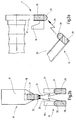
- FIG. 1 shows a schematic side view of an embodiment of a grounding switch according to the invention in an open position
- FIGS. 2a, 2b show a side view and a plan view of the earthing switch of FIG. 1 in an intermediate position
- FIGS. 3a, 3b show a side view and a plan view of the earthing switch of FIG. 1 in a closed position.
- grounding switch 10 is shown, with which an electrical connection to earth or ground can be made or interrupted by means of a mechanical operation.
- the grounding switch 10 can be used in particular in a medium-voltage switchgear.
- the earthing switch 10 has a fixed contact 11 and a movable contact 12. Are the two contacts 11, 12 arranged separately from each other, as shown in the FIG. 1 If this is the case, then there is no electrical connection. In the FIG. 1 Therefore, the open position of the earthing switch 10 is shown. In contrast, the two contacts 11, 12 are arranged so that they touch, as in the FIGS. 3a, 3b the case is, so there is an electrical connection. In the FIGS. 3a, 3b Therefore, the closed position of the earthing switch 10 is shown.
- the fixed contact 11 is attached via an insulating holder 14 to a carrier 15.
- the fixed contact 11 has an approximately U-shaped form and consists of metal, for example copper.
- a first leg 17 of the fixed contact 11 is preferably mounted approximately perpendicular to the bracket 14.
- a second leg 19 is present, which is aligned approximately parallel to the first leg 17.
- the second shekel 19 is arranged on the holder 14 facing side of the first leg 17. Furthermore, the second leg 19 is shorter than the first leg, so that the free end of the second leg 19 has a distance from the holder 14.
- a burn-off contact 21 is provided, which consists of an electrically conductive material with the highest possible melting point.
- the erosion contact 21 is formed in the shape of a thimble, attached to the first leg 17 and aligned in the direction of the first leg 17.
- An approximately hemispherical formed dome 22 of the AbbrandWallets 21 is above the first leg 17 via.
- the movable contact 12 is held in a manner not shown pivotable about an axis 24 on the carrier 15.
- the movable contact 12 can from the in the FIG. 1 shown position by about 90 degrees in the in FIG. 3a shown position and pivoted vice versa.
- the movable contact 12 consists of two knife-like rods 26, 27. It is this particular to the top view of FIG. 2b directed.
- the two rods 26, 27 are made of metal, in particular of copper.
- the two rods 26, 27 are configured similarly and arranged parallel to each other and aligned.
- the two rods 26, 27 preferably have a U-shaped cross section, wherein the Point legs in opposite directions. This is in the plan view of FIG. 3b indicated by dashed lines.
- each rod 26 27 each have a Abbrandness 28, 29 is attached, which consist of an electrically conductive material with the highest possible melting point.
- the Abbrandcarde 28, 29 are each formed in the shape of a thimble and preferably approximately perpendicular to the longitudinal direction of the rods 26, 27 aligned.
- the approximately hemispherical formed peaks 30, 31 of the AbbrandWallete 28, 29 are about the rods 26, 27 and have approximately in the direction of the AbbrandWallet 21 of the fixed contact eleventh
- the distance between the two rods 26, 27 of the movable contact 12 in the direction of the axis 24 corresponds to the width of the second leg 19 of the fixed contact 11 in the same direction. This is evident in particular from the plan views of FIGS. 2b . 3b , In the closed position of the earthing switch 10 according to the FIGS. 3a, 3b is thus the second leg 19 of the fixed contact 11 between the two rods 26, 27 of the movable contact 12. The second leg 19 is in such a way on the two rods 26, 27 that an electrical contact is present.
- the movable contact 12 is pivoted about the axis 24 in the direction of the fixed contact 11 by a mechanical actuation, which may be caused by a drive. At some point, the movable contact 12 then reaches the in the FIGS. 2a, 2 B shown intermediate position. In this intermediate position between the open position of the FIG. 1 and the closed position of FIGS. 3a, 3b the distance between the movable contact 12 of the fixed contact 11 has become so low that a current-carrying arc is formed.
- FIG. 2b two arcs 33, 34 are shown, of which the first arc 33 from the AbbrandWallet 28 of the first rod 26 to the AbbrandWallet 22 of the fixed contact 11 and the second arc 34 from the AbbrandWallet 29 of the second rod 27 to the Abbrandcard 22 of the fixed contact 11th extends.
- the above-mentioned current-carrying arc is formed by at least one of these two arcs 33, 34. Subsequently, it is assumed that only the arc 33 is present. It is understood that the following explanations apply in a corresponding manner for the arc 34, if it is present.
- the base of the arc 33 is due to the configuration of Abbrand tokene 21, 28 on the top 30 of Abbrand tokens 28 of the movable contact 12 and on the top 22 of the Abbrand tokens 21 of the fixed contact 11. This results in particular from the FIG. 2a , The explained areas of the Abbrand tokene 21, 28 are thus present on the knobs 22, 30 of the Abbrandcarde 21, 28th
- FIGS. 3a, 3b can be taken that also the crests 30, 31 of the AbbrandWallete 28, 29 of the movable contact 12 locally in a completely different Area of the earthing switch 10 are located as the top 22 of the AbbrandWallets 21 of the fixed contact 11.
- the tips 30, 31 of the AbbrandWallete 28, 29 of the movable contact 12 and the top 22 of the AbbrandWallets 21 of the fixed contact 11 in the closed position of the earthing switch 10 can not touch.
- the fixed contact 11 and the movable contact 12 may be formed differently.
- the movable contact 12 may also transition from an open position to a closed position of the earthing switch 10 by means of a different movement, for example by means of a linear movement.
Landscapes
- Gas-Insulated Switchgears (AREA)
- Switch Cases, Indication, And Locking (AREA)
Description
- Die Erfindung betrifft einen Erdungsschalter nach dem Oberbegriff des Anspruchs 1. Ein entsprechender Hebeltrennschalter ist aus der
DE 89 07 091 U1 bekannt. - Bekannte Mittelspannungsschaltanlagen enthalten häufig Erdungsschalter, die in einer geschlossenen Stellung die Erdung von bestimmten Komponenten der Schaltanlage sicherstellen. Bekannte Erdungsschalter weisen einen Festkontakt und einen beweglichen Kontakt auf, wobei der bewegliche Kontakt mechanisch von einer geöffneten in die geschlossene Stellung und umgekehrt bewegt werden kann.
- Beim Übergang in die geschlossene Stellung ist es möglich, dass - bevor der Erdungsschalter seine geschlossene Stellung erreicht - ein Lichtbogen zwischen dem Festkontakt und dem beweglichen Kontakt entsteht. Dies hat zur Folge, dass es zu Aufschmelzungen des beweglichen und des Festkontakts kommt. Dies kann dazu führen, dass im geschlossenen Zustand des Erdungsschalters die nunmehr aneinander anliegenden Kontakte zumindest in einem gewissen Umfang miteinander verschweißen. Soll danach der Erdungsschalter wieder geöffnet werden, so erfordert dies einen erhöhten mechanischen Aufwand, um die entstandenen Verschweißungen wieder aufzubrechen. Im Extremfall ist die Verschweißung so stark, dass der Erdungsschalter nicht mehr betätigt werden kann.
- Aufgabe der Erfindung ist es, einen elektrischen Erdungsschalter zu schaffen, der die Möglichkeit eines Verschweißens der Kontakte vermindert.
- Die Erfindung löst diese Aufgabe durch einen Erdungsschalter nach dem Anspruch 1.
- Der erfindungsgemäße elektrische Erdungsschalter ist mit einem Festkontakt und einem beweglichen Kontakt versehen. Der bewegliche Kontakt ist von einer geöffneten in eine geschlossene Stellung und umgekehrt bewegbar. Erfindungsgemäß weisen der Festkontakt und der bewegliche Kontakt Abbrandkontakte aus einem elektrisch leitfähigen Material mit einem hohen Schmelzpunkt auf. Bei der Erfindung ist in der geschlossenen Stellung des Erdungsschalters eine elektrische Verbindung über Flächen geführt, die sich von den Bereichen der Abbrandkontakte, in denen sich die Fußpunkte des Lichtbogens befinden, örtlich unterscheiden. Damit wird gewährleistet, dass in der geschlossenen Stellung des Erdungsschalters keine Verschweißungen zwischen dem Festkontakt und dem beweglichen Kontakt entstehen.
- Bei einer besonders vorteilhaften Weiterbildung der Erfindung sind die Abbrandkontakte derart ausgebildet und/oder angeordnet, dass sich die Fußpunkte eines sich bei einer Bewegung des beweglichen Kontakts gegebenenfalls ausbildenden Lichtbogens in bestimmbaren Bereichen der Abbrandkontakte befinden, und dass sich diejenigen Bereiche der Abbrandkontakte, in denen sich die Fußpunkte des Lichtbogens befinden, in der geschlossenen Stellung des Erdungsschalters nicht berühren. Wenn somit beim Übergang in die geschlossene Stellung des Erdungsschalters durch den Lichtbogen irgendwelche Aufschmelzungen an den Abbrandkontakten entstehen, so hat dies bei dem erfindungsgemäßen Erdungsschalter keine Folgen. Dies ergibt sich daraus, dass sich die Bereiche der Aufschmelzungen in der geschlossenen Stellung des Erdungsschalters nicht berühren. Damit können sich die Aufschmelzungen der Abbrandkontakte in der geschlossenen Stellung auch nicht miteinander verschweißen. Bei dem erfindungsgemäßen Erdungsschalter können somit keine Verschweißungen des Festkontakts und des beweglichen Kontakts entstehen. Der erfindungsgemäße elektrische Erdungsschalter kann damit ohne einen größeren mechanischen Aufwand wieder geöffnet werden.
- Die Vermeidung von Verschweißungen zwischen dem Festkontakt und dem beweglichen Kontakt bringt somit den wesentlichen Vorteil mit sich, dass beim Öffnen des Erdungsschalters kein mechanischer Aufwand zum Aufbrechen derartiger Verschweißungen erforderlich ist. Der für die Betätigung des Erdungsschalters erforderliche Antrieb muss damit noch geringere mechanische Bedingungen erfüllen als vergleichbare bekannte Erdungsschalter.
- Bei einer Ausgestaltung der Erfindung sind die Bereiche der Abbrandkontakte, in denen sich die Fußpunkte des Lichtbogens befinden, im wesentlichen als Kuppen der Abbrandkontakte ausgebildet. Derartige Kuppen haben sich als besonders vorteilhafte Fußpunkte für Lichtbögen herausgestellt.
- Weitere Merkmale, Anwendungsmöglichkeiten und Vorteile der Erfindung ergeben sich aus der nachfolgenden Beschreibung von Ausführungsbeispielen der Erfindung, die in den Figuren der Zeichnung dargestellt sind. Dabei bilden alle beschriebenen oder dargestellten Merkmale für sich oder in beliebiger Kombination den Gegenstand der Erfindung, unabhängig von ihrer Zusammenfassung in den Patentansprüchen oder deren Rückbeziehung sowie unabhängig von ihrer Formulierung bzw. Darstellung in der Beschreibung bzw. in der Zeichnung.
-
Figur 1 zeigt eine schematische Seitenansicht eines Ausführungsbeispiels eines erfindungsgemäßen Erdungsschalters in einer geöffneten Stellung,Figuren 2a, 2b zeigen eine Seitenansicht und eine Draufsicht auf den Erdungsschalter derFigur 1 in einer Zwischenstellung, undFiguren 3a, 3b zeigen eine Seitenansicht und eine Draufsicht auf den Erdungsschalter derFigur 1 in einer geschlossenen Stellung. - In der
Figur 1 ist ein Erdungsschalter 10 dargestellt, mit dem eine elektrische Verbindung nach Erde bzw. Masse mittels einer mechanischen Betätigung hergestellt oder unterbrochen werden kann. Der Erdungsschalter 10 kann insbesondere bei einer Mittelspannungsschaltanlage zum Einsatz kommen. - Der Erdungsschalter 10 weist einen Festkontakt 11 und einen beweglichen Kontakt 12 auf. Sind die beiden Kontakte 11, 12 getrennt voneinander angeordnet, wie dies in der
Figur 1 der Fall ist, so liegt keine elektrische Verbindung vor. In derFigur 1 ist daher die geöffnete Stellung des Erdungsschalters 10 dargestellt. Sind die beiden Kontakte 11, 12 hingegen derart angeordnet, dass sie sich berühren, wie dies in denFiguren 3a, 3b der Fall ist, so ist eine elektrische Verbindung vorhanden. In denFiguren 3a, 3b ist daher die geschlossene Stellung des Erdungsschalters 10 dargestellt. - Der Festkontakt 11 ist über eine isolierende Halterung 14 an einem Träger 15 befestigt. Gemäß der Seitenansicht der
Figur 1 besitzt der Festkontakt 11 eine etwa U-förmige Gestalt und besteht aus Metall, beispielsweise aus Kupfer. Mit einem ersten Schenkel 17 ist der Festkontakt 11 vorzugsweise etwa lotrecht an der Halterung 14 angebracht. Über eine Querverbindung 18 ist ein zweiter Schenkel 19 vorhanden, der etwa parallel zum ersten Schenkel 17 ausgerichtet ist. Der zweite Schekel 19 ist auf der der Halterung 14 zugewandten Seite des ersten Schenkels 17 angeordnet. Weiterhin ist der zweite Schenkel 19 kürzer als der erste Schenkel, so dass das freie Ende des zweiten Schenkels 19 einen Abstand zu der Halterung 14 aufweist. - Im Übergangsbereich von dem ersten Schenkel 17 zu der Querverbindung 18 ist ein Abbrandkontakt 21 vorgesehen, der aus einem elektrisch leitfähigen Material mit einem möglichst hohen Schmelzpunkt besteht. Der Abbrandkontakt 21 ist in der Form eines Fingerhuts ausgebildet, auf den ersten Schenkel 17 aufgesteckt und in Richtung des ersten Schenkels 17 ausgerichtet. Eine etwa halbkugelförmig ausgebildete Kuppe 22 des Abbrandkontakts 21 steht über den ersten Schenkel 17 über.
- Der bewegliche Kontakt 12 ist in nicht-dargestellter Weise um eine Achse 24 schwenkbar an dem Träger 15 gehalten. Der bewegliche Kontakt 12 kann aus der in der
Figur 1 gezeigten Stellung um etwa 90 Grad in die in derFigur 3a gezeigte Stellung und umgekehrt geschwenkt werden. - Der bewegliche Kontakt 12 besteht aus zwei messerartigen Stangen 26, 27. Es wird hierzu insbesondere auf die Draufsicht der
Figur 2b verwiesen. Die beiden Stangen 26, 27 bestehen aus Metall, insbesondere aus Kupfer. Die beiden Stangen 26, 27 sind gleichartig ausgestaltet und parallel zueinander angeordnet und ausgerichtet. Die beiden Stangen 26, 27 besitzen vorzugsweise einen U-förmigen Querschnitt, wobei die Schenkel in entgegengesetzte Richtungen weisen. Dies ist in der Draufsicht derFigur 3b gestrichelt angedeutet. - An den freien Enden der beiden Stangen 26, 27 ist jeweils ein Abbrandkontakt 28, 29 angebracht, die aus einem elektrisch leitfähigen Material mit einem möglichst hohen Schmelzpunkt bestehen. Die Abbrandkontakte 28, 29 sind jeweils in der Form eines Fingerhuts ausgebildet und vorzugsweise etwa lotrecht zur Längsrichtung der Stangen 26, 27 ausgerichtet. Die etwa halbkugelförmig ausgebildeten Kuppen 30, 31 der Abbrandkontakte 28, 29 stehen über die Stangen 26, 27 über und weisen etwa in Richtung zu dem Abbrandkontakt 21 des Festkontakts 11.
- Der Abstand der beiden Stangen 26, 27 des beweglichen Kontakts 12 in Richtung der Achse 24 entspricht der Breite des zweiten Schenkels 19 des Festkontakts 11 in derselben Richtung. Dies ergibt sich insbesondere aus den Draufsichten der
Figuren 2b ,3b . In der geschlossenen Stellung des Erdungsschalters 10 gemäß denFiguren 3a, 3b befindet sich somit der zweite Schenkel 19 des Festkontakts 11 zwischen den beiden Stangen 26, 27 des beweglichen Kontakts 12. Der zweite Schenkel 19 liegt dabei derart an den beiden Stangen 26, 27 an, dass ein elektrischer Kontakt vorhanden ist. - Wie bereits erwähnt wurde, zeigt die
Figur 1 die geöffnete Stellung des Erdungsschalters 10. Aufgrund des Abstands des beweglichen Kontakts 12 von dem Festkontakt 11 besteht keine elektrische Verbindung zwischen den Kontakten 11, 12 und es kann auch kein Lichtbogen insbesondere zwischen den Abbrandkontakten 21, 28, 29 entstehen. - Es wird nunmehr davon ausgegangen, dass der bewegliche Kontakt 12 durch eine wie auch immer mittels eines Antriebs hervorgerufene mechanische Betätigung um die Achse 24 in Richtung zu dem Festkontakt 11 geschwenkt wird. Irgendwann erreicht der bewegliche Kontakt 12 dann die in den
Figuren 2a, 2b gezeigte Zwischenstellung. In dieser Zwischenstellung zwischen der geöffneten Stellung derFigur 1 und der geschlossenen Stellung derFiguren 3a, 3b ist der Abstand des beweglichen Kontakts 12 von dem Festkontakt 11 so gering geworden, dass ein stromführender Lichtbogen entsteht. - In der
Figur 2b sind zwei Lichtbögen 33, 34 dargestellt, von denen sich der erste Lichtbogen 33 von dem Abbrandkontakt 28 der ersten Stange 26 zu dem Abbrandkontakt 22 des Festkontakts 11 und der zweite Lichtbogen 34 von dem Abbrandkontakt 29 der zweiten Stange 27 zu dem Abbrandkontakt 22 des Festkontakts 11 erstreckt. Der vorstehend genannte stromführende Lichtbogen wird zumindest von einem dieser beiden Lichtbögen 33 , 34 gebildet. Nachfolgend wird davon ausgegangen, dass nur der Lichtbogen 33 vorhanden ist. Es versteht sich, dass die nachfolgenden Erläuterungen in entsprechender Weise auch für den Lichtbogen 34 gelten, sofern er vorhanden ist. - Wenn sich ein Lichtbogen zwischen zwei Abbrandkontakten erstreckt, so hängt die Lage der Fußpunkte dieses Lichtbogens ganz allgemein von der Ausbildung der Abbrandkontakte sowie von deren Anordnung zueinander ab. Die Bereiche, in denen sich die Fußpunkte bewegen, können insbesondere aus dem elektrodynamischen Verhalten des Lichtbogens abgeleitet und/oder durch Versuche ermittelt werden.
- Bei dem vorliegenden Ausführungsbeispiel befindet sich der Fußpunkt des Lichtbogens 33 aufgrund der Ausgestaltung der Abbrandkontakte 21, 28 auf der Kuppe 30 des Abbrandkontakts 28 des beweglichen Kontakts 12 sowie auf der Kuppe 22 des Abbrandkontakts 21 des Festkontakts 11. Dies ergibt sich insbesondere aus der
Figur 2a . Die erläuterten Bereiche der Abbrandkontakte 21, 28 befinden sich also vorliegend auf den Kuppen 22, 30 der Abbrandkontakte 21, 28. - In der Zwischenstellung der
Figuren 2a, 2b ist es aufgrund der hohen Temperaturen des Lichtbogens 33 möglich, dass es in den Bereichen der Kuppen 22, 30 der Abbrandkontakte 21, 28 gegebenenfalls zu sogenannten Aufschmelzungen kommt. Dies bedeutet, dass das dort vorhandene Material der Abbrandkontakte 21, 28 in einem gewissen Umfang schmilzt und dadurch in einen weichen oder nahezu flüssigen Zustand übergeht. - Es wird nunmehr davon ausgegangen, dass der bewegliche Kontakt 12 durch die erwähnte mechanische Betätigung weiter um die Achse 24 in Richtung zu dem Festkontakt 11 geschwenkt wird. Irgendwann erreicht der bewegliche Kontakt 12 dann die in den
Figuren 3a, 3b gezeigte geschlossene Stellung des Erdungsschalters 10. - Wie bereits erwähnt wurde, befindet sich nunmehr der zweite Schenkel 19 des Festkontakts 11 zwischen den beiden Stangen 26, 27 des beweglichen Kontakts 12, so dass eine elektrische Verbindung vorhanden ist. Diese elektrische Verbindung ist dabei nicht über die erläuterten Bereiche der Abbrandkontakte 28, 29, 21 der beweglichen und des Festkontakts 12, 11 geführt, sondern unabhängig von diesen Bereichen. So führt die elektrische Verbindung zwischen dem Festkontakt 11 und dem beweglichen Kontakt 12 von dem zweiten Schenkel 19 des Festkontakts 11 zu den beiden Stangen 26, 27 des beweglichen Kontakts 12. Wie sich insbesondere aus der
Figur 3b ergibt, liegen diejenigen Flächen 36 des zweiten Schenkels 19, die in derselben Ebene liegen wie die U-Form des Festkontakts 11, an den einander zugewandten Flächen 37 der beiden Stangen 26, 27 an. Diese Flächen 36, 37 befinden sich somit in der geschlossenen Stellung des Erdungsschalters 10 derFiguren 3a, 3b örtlich in einem völlig anderen Bereich des Erdungsschalters 10 als die Kuppen 22, 30, 31 der Abbrandkontakte 21, 28, 29. - Weiterhin kann den
Figuren 3a, 3b entnommen werden, dass sich auch die Kuppen 30, 31 der Abbrandkontakte 28, 29 des beweglichen Kontakts 12 örtlich in einem völlig anderen Bereich des Erdungsschalters 10 befinden als die Kuppe 22 des Abbrandkontakts 21 des Festkontakts 11. Insbesondere geht aus denFiguren 3a, 3b hervor, dass sich die die Kuppen 30, 31 der Abbrandkontakte 28, 29 des beweglichen Kontakts 12 und die Kuppe 22 des Abbrandkontakts 21 des Festkontakts 11 in der geschlossenen Stellung des Erdungsschalters 10 nicht berühren können. - Beim Übergang in die in den
Figuren 3a, 3b gezeigte geschlossene Stellung des Erdungsschalters 10 kommutiert der Strom von dem Lichtbogen 33 auf die vorstehend erläuterte elektrische Verbindung. Der Lichtbogen 33 erlöscht damit. Aufgrund der galvanischen Verbindung über die einander berührenden Flächen 36, 37 entsteht dort kein Lichtbogen. - Wie erläutert wurde, kann es beim Übergang in die geschlossene Stellung des Erdungsschalters 10 im Bereich der Kuppen 22, 30, 31 der Abbrandkontakte 21, 28, 29 gegebenenfalls zu sogenannten Aufschmelzungen kommen. Wie ebenfalls erläutert wurde, können sich die Kuppen 30, 31 der Abbrandkontakte 28, 29 des beweglichen Kontakts 12 und die Kuppe 22 des Abbrandkontakts 21 des Festkontakts 11 in der geschlossenen Stellung des Erdungsschalters 10 jedoch nicht berühren. Dies bedeutet mit anderen Worten, dass diejenigen Bereiche, in denen sich die erläuterten Fußpunkte des Lichtbogens 33 befinden, in der geschlossenen Stellung des Erdungsschalters 10 nicht in Kontakt miteinander kommen können und sich damit nicht berühren. Damit ist es nicht möglich, dass sich die Abbrandkontakte 28, 29 des beweglichen Kontakts 12 und der Abbrandkontakt 21 des Festkontakts 11 aufgrund der durch den Lichtbogen 33 entstehenden Aufschmelzungen in der geschlossenen Stellung des Erdungsschalters 10 miteinander verschweißen.
- Weiterhin wurde erläutert, dass die elektrische Verbindung im geschlossenen Zustand des Erdungsschalters 10 über die Flächen 36, 37 führt, also über einen völlig anderen Bereich des Erdungsschalters 10 als die Kuppen 22, 30, 31 der Abbrandkontakte 21, 28, 29. Auch insoweit kann somit keine Verschweißung der Abbrandkontakte 28, 29 des beweglichen Kontakts 12 und des Abbrandkontakts 21 des Festkontakts 11 entstehen.
- Es versteht sich, dass der Festkontakt 11 und der bewegliche Kontakt 12 auch andersartig ausgebildet sein können. Insbesondere versteht es sich, dass der bewegliche Kontakt 12 auch mittels einer andersartigen Bewegung, beispielsweise mittels einer linearen Bewegung, von einer geöffneten Stellung in eine geschlossene Stellung des Erdungsschalters 10 übergehen kann.
Claims (7)
- Erdungsschalter (10) insbesondere für eine Mittelspannungsschaltanlage, mit einem Festkontakt (11) und einem beweglichen Kontakt (12), wobei der bewegliche Kontakt (12) von einer geöffneten in eine geschlossene Stellung und umgekehrt bewegbar ist, und wobei der Festkontakt (11) und der bewegliche Kontakt (12) Abbrandkontakte (21, 28, 29) aus einem elektrisch leitfähigen Material mit einem hohen Schmelzpunkt aufweisen, dadurch gekennzeichnet, dass in der geschlossenen Stellung des Erdungsschalters (10) eine elektrische Verbindung über Flächen (36, 37) geführt ist, die sich von den Bereichen der Abbrandkontakte (21, 28, 29), in denen sich die Fußpunkte eines Lichtbogens (33, 34) befinden, örtlich unterscheiden, und dass ein Strom beim Übergang in die geschlossene Stellung von dem Lichtbogen auf die elektrische Verbindung kommutiert.
- Erdungsschalter (10) nach Anspruch 1, wobei die Abbrandkontakte (21, 28, 29) derart ausgebildet und/oder angeordnet sind, dass sich die Fußpunkte eines sich bei einer Bewegung des beweglichen Kontakts (12) gegebenenfalls ausbildenden Lichtbogens (33, 34) in bestimmbaren Bereichen der Abbrandkontakte (21, 28, 29) befinden, und wobei diejenigen Bereiche der Abbrandkontakte (21, 28, 29), in denen sich die Fußpunkte des Lichtbogens (33, 34) befinden, sich in der geschlossenen Stellung des Erdungsschalters (10) nicht berühren.
- Erdungsschalter (10) nach Anspruch 2, wobei derjenige Bereich des Abbrandkontakts (21) des Festkontakts (11) sowie derjenige Bereich des Abbrandkontakts (28, 29) des beweglichen Kontakts (12), in denen sich die Fußpunkte des Lichtbogens (33, 34) befinden, sich in der geschlossenen Stellung örtlich in unterschiedlichen Bereichen des Erdungsschalters (10) befinden.
- Erdungsschalter (10) nach einem der vorstehenden Ansprüche, wobei die Bereiche der Abbrandkontakte (21, 28, 29), in denen sich die Fußpunkte des Lichtbogens (33, 34) befinden, im wesentlichen als Kuppen (22, 30, 31) der Abbrandkontakte (21, 28, 29) ausgebildet sind.
- Erdungsschalter (10) nach einem der vorstehenden Ansprüche, wobei der Festkontakt (11) einen ersten Schenkel (17) aufweist, dem der Abbrandkontakt (21) zugeordnet ist, wobei der bewegliche Kontakt (12) zwei Stangen (26, 27) aufweist, die mit jeweils einem Abbrandkontakt (28, 29) versehen sind, und wobei der dem ersten Schenkel (17) zugeordnete Abbrandkontakt (21) und die den Stangen (26, 27) zugehörigen Abbrandkontakte (28, 29) in der geschlossenen Stellung des Erdungsschalters (10) sich örtlich in unterschiedlichen Bereichen des Erdungsschalters (10) befinden.
- Erdungsschalter (10) nach Anspruch 5, wobei der Festkontakt (11) einen zweiten Schenkel (19) aufweist, und wobei in der geschlossenen Stellung des Erdungsschalters (10) eine elektrische Verbindung zwischen dem zweiten Schenkel (17) des Festkontakts (11) und den Stangen (26, 27) des beweglichen Kontakts (12) vorhanden ist.
- Erdungsschalter (10) nach einem der vorstehenden Ansprüche, wobei der bewegliche Kontakt (12) durch eine Schwenkbewegung von der geöffneten in die geschlossene Stellung bewegbar ist.
Applications Claiming Priority (1)
| Application Number | Priority Date | Filing Date | Title |
|---|---|---|---|
| DE200910032540 DE102009032540A1 (de) | 2009-07-10 | 2009-07-10 | Erdungsschalter insbesondere für eine Mittelspannungsschaltanlage |
Publications (3)
| Publication Number | Publication Date |
|---|---|
| EP2273524A2 EP2273524A2 (de) | 2011-01-12 |
| EP2273524A3 EP2273524A3 (de) | 2012-02-29 |
| EP2273524B1 true EP2273524B1 (de) | 2016-03-02 |
Family
ID=42937738
Family Applications (1)
| Application Number | Title | Priority Date | Filing Date |
|---|---|---|---|
| EP10161962.5A Revoked EP2273524B1 (de) | 2009-07-10 | 2010-05-05 | Erdungsschalter insbesondere für eine Mittelspannungsschaltanlage |
Country Status (2)
| Country | Link |
|---|---|
| EP (1) | EP2273524B1 (de) |
| DE (1) | DE102009032540A1 (de) |
Families Citing this family (4)
| Publication number | Priority date | Publication date | Assignee | Title |
|---|---|---|---|---|
| FI11882U1 (fi) * | 2017-09-15 | 2017-12-05 | Abb Oy | Sähkökytkin |
| CN112820562A (zh) * | 2020-11-16 | 2021-05-18 | 平高集团有限公司 | 一种接地开关装置和开关柜 |
| CN120048683A (zh) * | 2023-11-24 | 2025-05-27 | Abb瑞士股份有限公司 | 三工位开关及相应的开关柜 |
| FR3158829A1 (fr) * | 2024-01-31 | 2025-08-01 | Schneider Electric Industries Sas | Dispositif de coupure de courant électrique |
Citations (1)
| Publication number | Priority date | Publication date | Assignee | Title |
|---|---|---|---|---|
| DE8907091U1 (de) | 1989-06-07 | 1989-09-14 | Siemens AG, 1000 Berlin und 8000 München | Kontaktvorrichtung für Hebeltrennschalter |
Family Cites Families (3)
| Publication number | Priority date | Publication date | Assignee | Title |
|---|---|---|---|---|
| DE3235380A1 (de) * | 1982-09-24 | 1984-03-29 | Ruhrtal Elektrizitätsgesellschaft Hartig GmbH & Co, 4300 Essen | Gegenkontakt fuer trennschalter |
| DE3436173A1 (de) * | 1984-08-22 | 1986-03-06 | BBC Aktiengesellschaft Brown, Boveri & Cie., Baden, Aargau | Schaltanlage |
| WO1999052119A1 (de) * | 1998-04-03 | 1999-10-14 | Siemens Aktiengesellschaft | Kapselungsbaustein mit einem in eine strombahn integrierten drei-stellungs-schalter für eine gasisolierte schaltanlage |
-
2009
- 2009-07-10 DE DE200910032540 patent/DE102009032540A1/de not_active Ceased
-
2010
- 2010-05-05 EP EP10161962.5A patent/EP2273524B1/de not_active Revoked
Patent Citations (1)
| Publication number | Priority date | Publication date | Assignee | Title |
|---|---|---|---|---|
| DE8907091U1 (de) | 1989-06-07 | 1989-09-14 | Siemens AG, 1000 Berlin und 8000 München | Kontaktvorrichtung für Hebeltrennschalter |
Also Published As
| Publication number | Publication date |
|---|---|
| EP2273524A3 (de) | 2012-02-29 |
| EP2273524A2 (de) | 2011-01-12 |
| DE102009032540A1 (de) | 2011-01-13 |
Similar Documents
| Publication | Publication Date | Title |
|---|---|---|
| EP4004958B1 (de) | Stromtrenner | |
| DE2443141B2 (de) | Vakuumschalter mit einem Vakuumgehäuse | |
| DE60002432T2 (de) | Vakuumschaltvorrichtung | |
| EP2273524B1 (de) | Erdungsschalter insbesondere für eine Mittelspannungsschaltanlage | |
| DE102011119318B4 (de) | Stufenschalter mit Vakuumschaltröhren | |
| DE112010005162B4 (de) | Vakuum-leistungsschalter | |
| DE19631323C1 (de) | Druckgasschalter | |
| EP2063442A1 (de) | Leistungsschalter mit flexiblen Leitern | |
| EP3928344B1 (de) | Optimierter dreistellungsschalter | |
| EP4097749A1 (de) | Schalter für einen laststufenschalter und lastumschalter für einen laststufenschalter | |
| DE60101996T3 (de) | Vakuumschaltrohr | |
| DE1282768B (de) | Spulenanordnung zur Erzeugung eines Magnetfeldes in einem elektrischen Leistungsschalter | |
| EP0198506B1 (de) | Freiluftschaltgerät für Hochspannungsschaltanlagen | |
| WO2021058231A1 (de) | Baugruppe für einen hochspannungs-leistungsschalter und entsprechender hochspannungs-leistungsschalter | |
| WO2020025410A1 (de) | Schliesskontaktsystem | |
| EP3794621B1 (de) | Kontaktsystem für einen laststufenschalter | |
| DE102019117804B4 (de) | Schalteinrichtung mit einem elektrischen Kontaktsystem | |
| DE102007063446B3 (de) | Vakuumschaltröhre | |
| EP3469611B1 (de) | Kontaktanordnung für ein hochspannungs-schaltgerät sowie dessen verwendung und herstellung | |
| DE3235353C2 (de) | ||
| DE3411784A1 (de) | Kontakte fuer einen vakuumschalter | |
| EP2728597B1 (de) | Schaltgerät mit einer Kontaktanordnung | |
| DE102006004401B3 (de) | Kontaktsystem für ein elektrisches Schaltgerät | |
| EP3807919A1 (de) | Trennschalter mit zwei relativ zueinander bewegbaren kontaktteilen | |
| DE19831021C1 (de) | Mittelspannungs-Lasttrennschalter und Einschlagkontakt |
Legal Events
| Date | Code | Title | Description |
|---|---|---|---|
| PUAI | Public reference made under article 153(3) epc to a published international application that has entered the european phase |
Free format text: ORIGINAL CODE: 0009012 |
|
| AK | Designated contracting states |
Kind code of ref document: A2 Designated state(s): AL AT BE BG CH CY CZ DE DK EE ES FI FR GB GR HR HU IE IS IT LI LT LU LV MC MK MT NL NO PL PT RO SE SI SK SM TR |
|
| AX | Request for extension of the european patent |
Extension state: BA ME RS |
|
| PUAL | Search report despatched |
Free format text: ORIGINAL CODE: 0009013 |
|
| AK | Designated contracting states |
Kind code of ref document: A3 Designated state(s): AL AT BE BG CH CY CZ DE DK EE ES FI FR GB GR HR HU IE IS IT LI LT LU LV MC MK MT NL NO PL PT RO SE SI SK SM TR |
|
| AX | Request for extension of the european patent |
Extension state: BA ME RS |
|
| RIC1 | Information provided on ipc code assigned before grant |
Ipc: H01H 31/00 20060101AFI20120125BHEP Ipc: H01H 31/28 20060101ALI20120125BHEP Ipc: H01H 1/02 20060101ALI20120125BHEP Ipc: H01H 1/06 20060101ALI20120125BHEP Ipc: H02B 13/00 20060101ALI20120125BHEP Ipc: H01H 1/42 20060101ALI20120125BHEP |
|
| 17P | Request for examination filed |
Effective date: 20120601 |
|
| 17Q | First examination report despatched |
Effective date: 20141105 |
|
| GRAP | Despatch of communication of intention to grant a patent |
Free format text: ORIGINAL CODE: EPIDOSNIGR1 |
|
| INTG | Intention to grant announced |
Effective date: 20150910 |
|
| RAP1 | Party data changed (applicant data changed or rights of an application transferred) |
Owner name: SCHNEIDER ELECTRIC SACHSENWERK GMBH |
|
| GRAS | Grant fee paid |
Free format text: ORIGINAL CODE: EPIDOSNIGR3 |
|
| GRAA | (expected) grant |
Free format text: ORIGINAL CODE: 0009210 |
|
| AK | Designated contracting states |
Kind code of ref document: B1 Designated state(s): AL AT BE BG CH CY CZ DE DK EE ES FI FR GB GR HR HU IE IS IT LI LT LU LV MC MK MT NL NO PL PT RO SE SI SK SM TR |
|
| REG | Reference to a national code |
Ref country code: GB Ref legal event code: FG4D Free format text: NOT ENGLISH |
|
| REG | Reference to a national code |
Ref country code: AT Ref legal event code: REF Ref document number: 778526 Country of ref document: AT Kind code of ref document: T Effective date: 20160315 Ref country code: CH Ref legal event code: EP |
|
| REG | Reference to a national code |
Ref country code: IE Ref legal event code: FG4D Free format text: LANGUAGE OF EP DOCUMENT: GERMAN |
|
| REG | Reference to a national code |
Ref country code: FR Ref legal event code: PLFP Year of fee payment: 7 |
|
| REG | Reference to a national code |
Ref country code: DE Ref legal event code: R096 Ref document number: 502010011110 Country of ref document: DE |
|
| REG | Reference to a national code |
Ref country code: NL Ref legal event code: MP Effective date: 20160302 |
|
| REG | Reference to a national code |
Ref country code: LT Ref legal event code: MG4D |
|
| PG25 | Lapsed in a contracting state [announced via postgrant information from national office to epo] |
Ref country code: GR Free format text: LAPSE BECAUSE OF FAILURE TO SUBMIT A TRANSLATION OF THE DESCRIPTION OR TO PAY THE FEE WITHIN THE PRESCRIBED TIME-LIMIT Effective date: 20160603 Ref country code: HR Free format text: LAPSE BECAUSE OF FAILURE TO SUBMIT A TRANSLATION OF THE DESCRIPTION OR TO PAY THE FEE WITHIN THE PRESCRIBED TIME-LIMIT Effective date: 20160302 Ref country code: NO Free format text: LAPSE BECAUSE OF FAILURE TO SUBMIT A TRANSLATION OF THE DESCRIPTION OR TO PAY THE FEE WITHIN THE PRESCRIBED TIME-LIMIT Effective date: 20160602 Ref country code: ES Free format text: LAPSE BECAUSE OF FAILURE TO SUBMIT A TRANSLATION OF THE DESCRIPTION OR TO PAY THE FEE WITHIN THE PRESCRIBED TIME-LIMIT Effective date: 20160302 Ref country code: FI Free format text: LAPSE BECAUSE OF FAILURE TO SUBMIT A TRANSLATION OF THE DESCRIPTION OR TO PAY THE FEE WITHIN THE PRESCRIBED TIME-LIMIT Effective date: 20160302 |
|
| PG25 | Lapsed in a contracting state [announced via postgrant information from national office to epo] |
Ref country code: SE Free format text: LAPSE BECAUSE OF FAILURE TO SUBMIT A TRANSLATION OF THE DESCRIPTION OR TO PAY THE FEE WITHIN THE PRESCRIBED TIME-LIMIT Effective date: 20160302 Ref country code: BE Free format text: LAPSE BECAUSE OF NON-PAYMENT OF DUE FEES Effective date: 20160531 Ref country code: LV Free format text: LAPSE BECAUSE OF FAILURE TO SUBMIT A TRANSLATION OF THE DESCRIPTION OR TO PAY THE FEE WITHIN THE PRESCRIBED TIME-LIMIT Effective date: 20160302 Ref country code: PL Free format text: LAPSE BECAUSE OF FAILURE TO SUBMIT A TRANSLATION OF THE DESCRIPTION OR TO PAY THE FEE WITHIN THE PRESCRIBED TIME-LIMIT Effective date: 20160302 Ref country code: LT Free format text: LAPSE BECAUSE OF FAILURE TO SUBMIT A TRANSLATION OF THE DESCRIPTION OR TO PAY THE FEE WITHIN THE PRESCRIBED TIME-LIMIT Effective date: 20160302 Ref country code: NL Free format text: LAPSE BECAUSE OF FAILURE TO SUBMIT A TRANSLATION OF THE DESCRIPTION OR TO PAY THE FEE WITHIN THE PRESCRIBED TIME-LIMIT Effective date: 20160302 |
|
| PG25 | Lapsed in a contracting state [announced via postgrant information from national office to epo] |
Ref country code: EE Free format text: LAPSE BECAUSE OF FAILURE TO SUBMIT A TRANSLATION OF THE DESCRIPTION OR TO PAY THE FEE WITHIN THE PRESCRIBED TIME-LIMIT Effective date: 20160302 Ref country code: IS Free format text: LAPSE BECAUSE OF FAILURE TO SUBMIT A TRANSLATION OF THE DESCRIPTION OR TO PAY THE FEE WITHIN THE PRESCRIBED TIME-LIMIT Effective date: 20160702 |
|
| PG25 | Lapsed in a contracting state [announced via postgrant information from national office to epo] |
Ref country code: PT Free format text: LAPSE BECAUSE OF FAILURE TO SUBMIT A TRANSLATION OF THE DESCRIPTION OR TO PAY THE FEE WITHIN THE PRESCRIBED TIME-LIMIT Effective date: 20160704 Ref country code: SM Free format text: LAPSE BECAUSE OF FAILURE TO SUBMIT A TRANSLATION OF THE DESCRIPTION OR TO PAY THE FEE WITHIN THE PRESCRIBED TIME-LIMIT Effective date: 20160302 Ref country code: RO Free format text: LAPSE BECAUSE OF FAILURE TO SUBMIT A TRANSLATION OF THE DESCRIPTION OR TO PAY THE FEE WITHIN THE PRESCRIBED TIME-LIMIT Effective date: 20160302 Ref country code: SK Free format text: LAPSE BECAUSE OF FAILURE TO SUBMIT A TRANSLATION OF THE DESCRIPTION OR TO PAY THE FEE WITHIN THE PRESCRIBED TIME-LIMIT Effective date: 20160302 Ref country code: CZ Free format text: LAPSE BECAUSE OF FAILURE TO SUBMIT A TRANSLATION OF THE DESCRIPTION OR TO PAY THE FEE WITHIN THE PRESCRIBED TIME-LIMIT Effective date: 20160302 |
|
| REG | Reference to a national code |
Ref country code: DE Ref legal event code: R026 Ref document number: 502010011110 Country of ref document: DE |
|
| PLBI | Opposition filed |
Free format text: ORIGINAL CODE: 0009260 |
|
| PG25 | Lapsed in a contracting state [announced via postgrant information from national office to epo] |
Ref country code: IT Free format text: LAPSE BECAUSE OF FAILURE TO SUBMIT A TRANSLATION OF THE DESCRIPTION OR TO PAY THE FEE WITHIN THE PRESCRIBED TIME-LIMIT Effective date: 20160302 Ref country code: LU Free format text: LAPSE BECAUSE OF FAILURE TO SUBMIT A TRANSLATION OF THE DESCRIPTION OR TO PAY THE FEE WITHIN THE PRESCRIBED TIME-LIMIT Effective date: 20160505 |
|
| REG | Reference to a national code |
Ref country code: CH Ref legal event code: PL |
|
| 26 | Opposition filed |
Opponent name: FRITZ DRIESCHER KG SPEZIALFABRIK FUER ELEKTRIZITAE Effective date: 20161202 |
|
| PLAX | Notice of opposition and request to file observation + time limit sent |
Free format text: ORIGINAL CODE: EPIDOSNOBS2 |
|
| PG25 | Lapsed in a contracting state [announced via postgrant information from national office to epo] |
Ref country code: CH Free format text: LAPSE BECAUSE OF NON-PAYMENT OF DUE FEES Effective date: 20160531 Ref country code: LI Free format text: LAPSE BECAUSE OF NON-PAYMENT OF DUE FEES Effective date: 20160531 Ref country code: DK Free format text: LAPSE BECAUSE OF FAILURE TO SUBMIT A TRANSLATION OF THE DESCRIPTION OR TO PAY THE FEE WITHIN THE PRESCRIBED TIME-LIMIT Effective date: 20160302 |
|
| REG | Reference to a national code |
Ref country code: IE Ref legal event code: MM4A |
|
| PG25 | Lapsed in a contracting state [announced via postgrant information from national office to epo] |
Ref country code: SI Free format text: LAPSE BECAUSE OF FAILURE TO SUBMIT A TRANSLATION OF THE DESCRIPTION OR TO PAY THE FEE WITHIN THE PRESCRIBED TIME-LIMIT Effective date: 20160302 Ref country code: BG Free format text: LAPSE BECAUSE OF FAILURE TO SUBMIT A TRANSLATION OF THE DESCRIPTION OR TO PAY THE FEE WITHIN THE PRESCRIBED TIME-LIMIT Effective date: 20160602 |
|
| REG | Reference to a national code |
Ref country code: FR Ref legal event code: PLFP Year of fee payment: 8 |
|
| PLBB | Reply of patent proprietor to notice(s) of opposition received |
Free format text: ORIGINAL CODE: EPIDOSNOBS3 |
|
| PG25 | Lapsed in a contracting state [announced via postgrant information from national office to epo] |
Ref country code: IE Free format text: LAPSE BECAUSE OF NON-PAYMENT OF DUE FEES Effective date: 20160505 |
|
| REG | Reference to a national code |
Ref country code: AT Ref legal event code: MM01 Ref document number: 778526 Country of ref document: AT Kind code of ref document: T Effective date: 20160505 |
|
| PG25 | Lapsed in a contracting state [announced via postgrant information from national office to epo] |
Ref country code: AT Free format text: LAPSE BECAUSE OF NON-PAYMENT OF DUE FEES Effective date: 20160505 |
|
| REG | Reference to a national code |
Ref country code: FR Ref legal event code: PLFP Year of fee payment: 9 |
|
| PG25 | Lapsed in a contracting state [announced via postgrant information from national office to epo] |
Ref country code: CY Free format text: LAPSE BECAUSE OF FAILURE TO SUBMIT A TRANSLATION OF THE DESCRIPTION OR TO PAY THE FEE WITHIN THE PRESCRIBED TIME-LIMIT Effective date: 20160302 Ref country code: HU Free format text: LAPSE BECAUSE OF FAILURE TO SUBMIT A TRANSLATION OF THE DESCRIPTION OR TO PAY THE FEE WITHIN THE PRESCRIBED TIME-LIMIT; INVALID AB INITIO Effective date: 20100505 |
|
| REG | Reference to a national code |
Ref country code: DE Ref legal event code: R064 Ref document number: 502010011110 Country of ref document: DE Ref country code: DE Ref legal event code: R103 Ref document number: 502010011110 Country of ref document: DE |
|
| PG25 | Lapsed in a contracting state [announced via postgrant information from national office to epo] |
Ref country code: TR Free format text: LAPSE BECAUSE OF FAILURE TO SUBMIT A TRANSLATION OF THE DESCRIPTION OR TO PAY THE FEE WITHIN THE PRESCRIBED TIME-LIMIT Effective date: 20160302 Ref country code: MC Free format text: LAPSE BECAUSE OF FAILURE TO SUBMIT A TRANSLATION OF THE DESCRIPTION OR TO PAY THE FEE WITHIN THE PRESCRIBED TIME-LIMIT Effective date: 20160302 Ref country code: MT Free format text: LAPSE BECAUSE OF FAILURE TO SUBMIT A TRANSLATION OF THE DESCRIPTION OR TO PAY THE FEE WITHIN THE PRESCRIBED TIME-LIMIT Effective date: 20160302 Ref country code: MK Free format text: LAPSE BECAUSE OF FAILURE TO SUBMIT A TRANSLATION OF THE DESCRIPTION OR TO PAY THE FEE WITHIN THE PRESCRIBED TIME-LIMIT Effective date: 20160302 |
|
| PGFP | Annual fee paid to national office [announced via postgrant information from national office to epo] |
Ref country code: DE Payment date: 20180424 Year of fee payment: 9 |
|
| PGFP | Annual fee paid to national office [announced via postgrant information from national office to epo] |
Ref country code: FR Payment date: 20180411 Year of fee payment: 9 |
|
| RDAF | Communication despatched that patent is revoked |
Free format text: ORIGINAL CODE: EPIDOSNREV1 |
|
| PG25 | Lapsed in a contracting state [announced via postgrant information from national office to epo] |
Ref country code: AL Free format text: LAPSE BECAUSE OF FAILURE TO SUBMIT A TRANSLATION OF THE DESCRIPTION OR TO PAY THE FEE WITHIN THE PRESCRIBED TIME-LIMIT Effective date: 20160302 |
|
| PGFP | Annual fee paid to national office [announced via postgrant information from national office to epo] |
Ref country code: GB Payment date: 20180502 Year of fee payment: 9 |
|
| RDAG | Patent revoked |
Free format text: ORIGINAL CODE: 0009271 |
|
| STAA | Information on the status of an ep patent application or granted ep patent |
Free format text: STATUS: PATENT REVOKED |
|
| 27W | Patent revoked |
Effective date: 20180608 |
|
| GBPR | Gb: patent revoked under art. 102 of the ep convention designating the uk as contracting state |
Effective date: 20180608 |
|
| REG | Reference to a national code |
Ref country code: BE Ref legal event code: MM Effective date: 20160531 |
|
| REG | Reference to a national code |
Ref country code: AT Ref legal event code: MA03 Ref document number: 778526 Country of ref document: AT Kind code of ref document: T Effective date: 20180608 |