EP2273534A1 - Dispositif de génération d'ultraviolets et dispositif d'éclairage l'utilisant - Google Patents
Dispositif de génération d'ultraviolets et dispositif d'éclairage l'utilisant Download PDFInfo
- Publication number
- EP2273534A1 EP2273534A1 EP09728158A EP09728158A EP2273534A1 EP 2273534 A1 EP2273534 A1 EP 2273534A1 EP 09728158 A EP09728158 A EP 09728158A EP 09728158 A EP09728158 A EP 09728158A EP 2273534 A1 EP2273534 A1 EP 2273534A1
- Authority
- EP
- European Patent Office
- Prior art keywords
- gas
- discharge
- ultraviolet
- nitric oxide
- generating device
- Prior art date
- Legal status (The legal status is an assumption and is not a legal conclusion. Google has not performed a legal analysis and makes no representation as to the accuracy of the status listed.)
- Granted
Links
Images





Classifications
-
- H—ELECTRICITY
- H01—ELECTRIC ELEMENTS
- H01J—ELECTRIC DISCHARGE TUBES OR DISCHARGE LAMPS
- H01J61/00—Gas-discharge or vapour-discharge lamps
- H01J61/02—Details
- H01J61/12—Selection of substances for gas fillings; Specified operating pressure or temperature
- H01J61/16—Selection of substances for gas fillings; Specified operating pressure or temperature having helium, argon, neon, krypton, or xenon as the principle constituent
-
- H—ELECTRICITY
- H01—ELECTRIC ELEMENTS
- H01J—ELECTRIC DISCHARGE TUBES OR DISCHARGE LAMPS
- H01J61/00—Gas-discharge or vapour-discharge lamps
- H01J61/02—Details
- H01J61/04—Electrodes; Screens; Shields
- H01J61/10—Shields, screens, or guides for influencing the discharge
- H01J61/106—Shields, screens, or guides for influencing the discharge using magnetic means
-
- H—ELECTRICITY
- H01—ELECTRIC ELEMENTS
- H01J—ELECTRIC DISCHARGE TUBES OR DISCHARGE LAMPS
- H01J61/00—Gas-discharge or vapour-discharge lamps
- H01J61/02—Details
- H01J61/12—Selection of substances for gas fillings; Specified operating pressure or temperature
-
- H—ELECTRICITY
- H01—ELECTRIC ELEMENTS
- H01J—ELECTRIC DISCHARGE TUBES OR DISCHARGE LAMPS
- H01J61/00—Gas-discharge or vapour-discharge lamps
- H01J61/02—Details
- H01J61/12—Selection of substances for gas fillings; Specified operating pressure or temperature
- H01J61/14—Selection of substances for gas fillings; Specified operating pressure or temperature having one or more carbon compounds as the principal constituents
-
- H—ELECTRICITY
- H01—ELECTRIC ELEMENTS
- H01J—ELECTRIC DISCHARGE TUBES OR DISCHARGE LAMPS
- H01J65/00—Lamps without any electrode inside the vessel; Lamps with at least one main electrode outside the vessel
- H01J65/04—Lamps in which a gas filling is excited to luminesce by an external electromagnetic field or by external corpuscular radiation, e.g. for indicating plasma display panels
- H01J65/042—Lamps in which a gas filling is excited to luminesce by an external electromagnetic field or by external corpuscular radiation, e.g. for indicating plasma display panels by an external electromagnetic field
- H01J65/046—Lamps in which a gas filling is excited to luminesce by an external electromagnetic field or by external corpuscular radiation, e.g. for indicating plasma display panels by an external electromagnetic field the field being produced by using capacitive means around the vessel
Definitions
- the present invention relates to a mercury-less ultraviolet generating device, which utilizes a novel electric discharge technology of efficiently and stably generating a high-density weakly-ionized low-temperature plasma, and also relates to a lighting device, which applies the generated ultraviolet rays to a lighting.
- Ultraviolet and vacuum ultraviolet rays obtained from a discharge gas of hydrogen, xenon, or krypton are widely used in various fields such as photochemical engineering, semiconductor manufacturing process, food and medical sterilization, and lighting devices when the rays are converted into visible light by exciting fluorescent material.
- mercury is a harmful substance to global environment and is refrained from being used, while xenon and krypton gases are rare materials, and their use is limited. Therefore, it is necessary to develop an ultraviolet and vacuum ultraviolet generating device and a lighting device using a usual molecular gas, other than mercury and rare gasses, as a discharge gas.
- each emitted light spectrum is discontinuous and has a line spectrum with a wavelength unique to a discharge gas. This is because, when atoms excited with electrons are relaxed, a transition between in specific energy state levels occurs, and according to this, lights are emitted.
- each emitted light spectrum is continuous. This is because vibrational and rotational excitation states are added to an electronic excitation energy state to make a transition between energy levels continuous. Therefore, to efficiently obtain ultraviolet radiation from a molecular gas, it is required to select a gas with an appropriate energy transition state from various molecular gases. Also, in glow discharge plasma, to effectively excite the molecular gas with a sufficient strength, a high-output, highly-efficient plasma generating device is required.
- the method of constituting said electrode assembly is to closely attach and fix a plurality of electrode pieces to a cooled inner wall of the device via an thermally conductive insulating sheet, and the method of constituting a magnetic field is to establish a magnetic field in the vicinity of each electrode surface to suppress outflow of plasma by attaching a plurality of magnets onto the outer wall of the device.
- the Applicant further discloses a high-output, highly-efficient discharge-type lighting device with a high energy-saving effect by using the wall-fixed electrode pieces to efficiently generate electric discharge with a phase-controlled polyphase alternating-current power supply and the multi-poled magnetic field in Japanese Patent No. 3472229 .
- the primary feature of the present invention is generating a plurality of ultraviolet rays by exciting a discharge gas with a weakly-ionized low-temperature plasma, wherein the discharge gas is a mixed gas of a nitric oxide and a diluent gas.
- Fig. 1 depicts a section view of a lighting device in which the present invention is implemented.
- twelve sheet-shaped divisional electrodes 1 are buried into a barrier layer 2 with slight spaces a therebetween, and are closely attached and fixed with a substrate 31 on a bottom surface of a flat container 3.
- An opposite surface facing the substrate 31 is covered with a light extraction window 32 with its inside coated with a fluorescent material b (not shown in Fig. 1 ) to shield the flat container 3 to form a low-pressure discharge chamber.
- the divisional electrodes 1 are disposed so as to have as large area as possible to cover the entire substrate 31.
- the barrier layer 2 a material with an excellent electric insulation and thermal conductivity is used, for example, quartz glass or boron nitride, to form an insulator layer.
- twelve+one rod magnets 4 arranged with adjacent polarities opposite to each other are closely attached and fixed each along the spaces a.
- the arrows depicted on the magnets 4 indicate directions of magnetic poles, and with these, a multi-poled magnetic field is formed so that the magnetic lines of force cover the surface of the divisional electrodes 1.
- the outside of the substrate 31 having the magnets 4 mounted thereon is covered with a magnetic shield plate 5, thereby not diverging the magnetic lines of force to the outside but concentrating them onto the inside.
- electromagnetic coils may be used in place of permanent magnets.
- sheet magnets 4 such as rubber magnets, may be interposed between the barrier layer 2 and the substrate 31 or be pasted on the outside of the substrate 31 to form a multi-poled magnetic field.
- the thickness of each of the magnets 4 is decreased, and accordingly the shape of the lighting device can be made thinner and compact.
- Fig. 1 depicts the case in which each magnet 4 is placed straight behind the space a between one divisional electrode 1 and another divisional electrode 1.
- the multi-poled magnetic field is formed so as to cover the surface of the divisional electrodes 1 with magnetic lines of force, and therefore plasma P is effectively confined near the surface of the divisional electrodes 1.
- plasma P is effectively confined near the surface of the divisional electrodes 1.
- a twelve-phase alternating-current power supply 6 having phases shifted by a 1/12 cycle and having the same amplitude is connected via feeding terminals 11 each mounted at one end of each divisional electrode 1.
- the twelve-phase alternating-current power supply 6 is configured by making a star connection of low-frequency alternating-current power supplies with their frequencies, amplitudes, and phases (including waveform) controlled. The entire power supply has a floating potential remained as it is by an isolation transformer, then discharge is caused only between the divisional electrodes 1.
- the lighting device in which the present invention is implemented is configured as described above.
- the inside of the flat container 3 is vacuum evacuated with an exhaust device (not shown), and 1 Torr or less of a molecular gas for use in discharge light emission fills therein or is flowed thereinto.
- This molecular gas is namely a discharge gas and, in the present invention, a mixed gas of nitric oxide and a diluent gas is used.
- a diluent gas a chemically stable gas having a metastable level slightly higher than an excitation level of nitric oxide of about 6 eV is used. Specifically, nitrogen gas is optimum.
- Fig. 10 depicts a potential-curve diagram of nitric oxide, in which the ultraviolet rays in the present invention are emitted when the electron state of nitric oxide transits from an energy level represented by a spectral term of A 2 ⁇ + to a level represented by X 2 ⁇ r.
- An energy difference therebetween is approximately 6 eV, and corresponds to energy of a photon having a wavelength of about 200 nm.
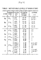
- Figs. 11 and 12 depict metastable levels of main molecules and atoms.
- a metastable level of A 3 ⁇ u is present, and its energy is 6.17 eV, and its lifetime is long with from 1.3 to 2.6 seconds, which can be found to be extremely long compared with a normal lifetime of about 10 -12 seconds.
- the molecular mass of nitrogen molecule is 28, and the molecular mass of nitric oxide is 30. Because of the similarity in mass, when these two collide with each other, energy is efficiently exchanged. That is, when N 2 in a metastable state of A 3 ⁇ u with energy of 6.17 eV collides with NO in a ground state, NO is efficiently excited to the level of A 2 ⁇ + having energy of 6 eV.
- Xenon Xe has a metastable level at an energy level of 8.32 eV, which is slightly higher than the excitation level of about 6 eV of nitric oxide, and therefore an effect approximately equivalent to that of the nitrogen gas can be expected.
- Xe has an atomic mass of 131, and is much heavier than nitric oxide having a molecular mass of 30. Therefore, when they are compared with each other, the nitrogen molecular gas (with a molecular weight of 28) is lighter than the xenon gas, and thus can be suitable as a diluent gas. Note that an upper diagram in Fig.
- the nitrogen molecules which form a main filling gas, are immediately recombined with oxygen dissociated from nitric oxide molecules due to discharge, and therefore changing the composition of the nitric oxide gas due to discharge is avoided and, as a result, stable, strong ultraviolet rays can be obtained.
- a molecular gas various compounds have been studied and tested so far. In particular, compounds that become a gas state at room temperature or when slightly heated, such as carbon C, nitrogen N, oxygen O, sulfur S, selenium Se, and tellurium Te, have been tested.
- a major problem is that, in a discharge state, a compound is dissociated to form another solid compound in a device and the composition of the molecular gas is changed from an initial state, or a light extraction window is fogged.
- the phase-controlled twelve-output alternating-current power supply of 1 kW or lower is connected to the twelve divisional electrodes 1 to supply discharge electrical energy.
- the plasma P occurs by alternating-current glow discharge along the surface of the divisional electrodes 1 covered with the barrier layer 2.
- twelve-phase alternating voltages are applied to the twelve divisional electrodes 1, discharge circulates once among the divisional electrodes 1 during one cycle, and therefore discharge rotates as many as applied frequencies during a second. Therefore, discharge occurs between any divisional electrodes 1 at any time, and continuous discharge occurs like high-frequency lighting, even with low-frequency alternating discharge.
- Plasma P occurring as a result of discharge is confined in a narrow, thin region by the multi-poled magnetic field, collision excitation with plasma of electrically-neutral molecular gas (neutral gas) becomes active, thereby increasing luminous density and luminous efficiency from the excited neutral gas.
- electrically-neutral molecular gas neutral gas
- As a result of such continuous discharge light having a wavelength unique to the molecular gas containing ultraviolet rays are stably emitted in a spatially-uniform manner over the entire electrodes. These ultraviolet rays are converted into visible light by the fluorescent material b coating the inside of the light extraction window 32. Since the plasma region and the light-emitting layer are thin, light is not reabsorbed and has a high luminance.
- the dimension and arrangement of the divisional electrodes are not restricted to those depicted in Fig. 1 .
- the number of phases of the alternating-current power supply is not restricted to twelve.
- the dimension and arrangement of the divisional electrodes and the number of phases and the magnitude of power of the alternating-current power supply are adjusted as appropriate so that ultraviolet radiation is optimum for a substance to be radiated.
- the generated ultraviolet rays are applied to a fluorescent material for conversion into visible light for a lighting device, also can be used for sterilization of foods and pharmaceuticals avoiding degeneration by heating and, furthermore, can be applied to photochemical reaction.
- Fig. 3 depicts discharge emission spectrums in a multi-poled magnetic field with three types of molecular gas.
- Figs. 3(a), (b), and (c) depict spectrums when nitrogen, nitric oxide, and a nitrogen-diluted (90%) nitric oxide (10%) gas were used, respectively.
- the vertical axis represents spectral radiant flux densities [ ⁇ W/cm 2 /nm] calibrated with a standard light source.
- the nitrogen gas in Fig. 3(a) as conventionally reported, ultraviolet radiation was observed from a wavelength region of from 300 nm to 380 nm.
- the radiant flux density is large when the concentration of nitric oxide of the nitrogen-diluted nitric oxide gas is within a range of from 5 to 50%, and is small when it is outside of this range.
- the reason for this is considered as follows. If the concentration of nitric oxide is smaller than 5%, the number of nitric oxide molecules, which are main constituents of ultraviolet and vacuum ultraviolet emission, is insufficient. If the concentration exceeds 50%, it becomes difficult to effectively excite nitric oxide by nitrogen molecules, which is a diluent gas.
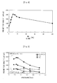
- Fig. 5 depicts radiant flux densities, obtained by integrating spectral radiant flux densities over an ultraviolet region (from 200 nm to 380 nm, with respect to pressure in three types of molecular gas.
- black circles represent radiant flux densities in the case of nitrogen molecules
- data with black triangular marks represents that in the case of nitric oxide
- data with black square marks represents that in the case of nitrogen-diluted nitric oxide (10%).
- data with white square marks connected by a broken line represents that in the case of nitrogen-diluted nitric oxide (10%) without a magnetic field. Without a magnetic field, little change was observed even when the pressure decreased.
- the ultraviolet luminous intensity increased.
- the multi-poled magnetic field in any of Fig. 3 , Fig. 4, and Fig. 5 is a multi-race-type multi-poled magnetic field.
- the magnitude of the ultraviolet radiation density with a pressure of the nitrogen-diluted nitric oxygen mixed gas of 0.3 Torr was 1.5 times as large as a value observed when mercury was used in the same device.
- argon gas was tried as a diluent gas of nitric oxide, ultraviolet radiation was smaller than that in the case of dilution with nitrogen.
- Fig. 6 depicts discharge emission spectrums in the multi-poled magnetic field with two types of molecular gas.
- Fig. 6(a) and 6(b) depict spectrums when hydrogen and hydrogen-diluted (90%) carbon oxide (10%) gas are used, respectively, as molecular gas.
- the gas pressure is 0.3 Torr
- the vertical axis represents spectral radiant flux densities [ ⁇ W/cm 2 /nm] calibrated with a standard light source.
- ultraviolet radiation from a short-wavelength region of about 300 nm or shorter was observed.
- the vertical axis represents radiant flux densities [ ⁇ W/cm 2 ] and the horizontal axis represents carbon oxide concentrations CO/H 2 +CO [%].
- the multi-poled magnetic fields in Fig. 6 and Fig. 7 are double-comb-type multi-poled magnetic fields. From Fig. 7 , it can be found that the radiant flux density is large when the concentration of carbon oxide of the hydrogen-diluted carbon oxide gas is within a range of from 1 to 15% and it is small outside of this range. The reason for this is considered as follows. If the concentration of carbon oxide is smaller than 1%, the number of carbon oxide molecules, which are main constituents of ultraviolet and vacuum ultraviolet emission, is insufficient.
- Fig. 9(a) had luminous intensity several times as strong as that of the double-comb-type magnetic field depicted in Fig. 9(b) .
- data with black square and white square marks in Fig. 9 represent radiant flux densities in a ultraviolet region, and is found by integrating spectral radiant flux densities within a range of wavelengths of from 200 nm to 380 nm.
- data with black circle and white circle marks in that figure represent those in a visible region, and is obtained by integrating spectral radiant flux densities within a range of wavelengths of from 380 nm to 780 nm.
- solid lines represent the case in the multi-poled magnetic field, and broken lines represent the case without a magnetic field.
Landscapes
- Physics & Mathematics (AREA)
- Electromagnetism (AREA)
- Engineering & Computer Science (AREA)
- Plasma & Fusion (AREA)
- Radiation-Therapy Devices (AREA)
- Plasma Technology (AREA)
- Gas-Filled Discharge Tubes (AREA)
- Discharge Lamp (AREA)
Applications Claiming Priority (3)
| Application Number | Priority Date | Filing Date | Title |
|---|---|---|---|
| JP2008096554 | 2008-04-02 | ||
| JP2008217557A JP2011023112A (ja) | 2008-08-27 | 2008-08-27 | 紫外線源および照明装置 |
| PCT/JP2009/056800 WO2009123258A1 (fr) | 2008-04-02 | 2009-04-01 | Dispositif de génération d'ultraviolets et dispositif d'éclairage l'utilisant |
Publications (3)
| Publication Number | Publication Date |
|---|---|
| EP2273534A1 true EP2273534A1 (fr) | 2011-01-12 |
| EP2273534A4 EP2273534A4 (fr) | 2012-09-19 |
| EP2273534B1 EP2273534B1 (fr) | 2013-06-12 |
Family
ID=41135625
Family Applications (1)
| Application Number | Title | Priority Date | Filing Date |
|---|---|---|---|
| EP09728158.8A Not-in-force EP2273534B1 (fr) | 2008-04-02 | 2009-04-01 | Dispositif de génération d'ultraviolets et dispositif d'éclairage l'utilisant |
Country Status (5)
| Country | Link |
|---|---|
| US (1) | US20110025221A1 (fr) |
| EP (1) | EP2273534B1 (fr) |
| KR (1) | KR101345881B1 (fr) |
| CN (1) | CN101981652B (fr) |
| WO (1) | WO2009123258A1 (fr) |
Families Citing this family (6)
| Publication number | Priority date | Publication date | Assignee | Title |
|---|---|---|---|---|
| JP5493100B2 (ja) * | 2008-12-04 | 2014-05-14 | 株式会社オーク製作所 | 放電ランプ |
| JP5565793B2 (ja) * | 2009-12-08 | 2014-08-06 | 学校法人立命館 | 深紫外発光素子及びその製造方法 |
| JP5783026B2 (ja) * | 2011-12-15 | 2015-09-24 | ウシオ電機株式会社 | 放電ランプ装置 |
| US9390892B2 (en) | 2012-06-26 | 2016-07-12 | Kla-Tencor Corporation | Laser sustained plasma light source with electrically induced gas flow |
| US9779872B2 (en) | 2013-12-23 | 2017-10-03 | Kla-Tencor Corporation | Apparatus and method for fine-tuning magnet arrays with localized energy delivery |
| US10091865B1 (en) * | 2017-11-13 | 2018-10-02 | The Boeing Company | Systems and methods for extending a lifespan of an excimer lamp |
Family Cites Families (23)
| Publication number | Priority date | Publication date | Assignee | Title |
|---|---|---|---|---|
| DE2246365C3 (de) * | 1972-09-21 | 1975-05-15 | Deutsche Forschungs- U. Versuchsanstalt Fuer Luft- Und Raumfahrt E.V., 5300 Bonn | Verfahren und Vorrichtung zur Bestimmung der Stickoxidkonzentration in einem Gasgemisch |
| DE2529037C3 (de) * | 1975-06-28 | 1978-03-09 | Philips Patentverwaltung Gmbh, 2000 Hamburg | Elektroradiographische Vorrichtung |
| DE2925410A1 (de) * | 1979-06-23 | 1981-01-08 | Hartmann & Braun Ag | Niederdruck-hohlkathodenlampe mit einer stickstoff-sauerstoff-fuellung |
| EP0110416B1 (fr) * | 1982-12-02 | 1989-07-26 | Shin-Etsu Chemical Co., Ltd. | Méthode pour augmenter la densité de la couleur et pour améliorer la solidité de teinture de tissus teints |
| DE3617110A1 (de) * | 1986-05-21 | 1987-11-26 | Leybold Heraeus Gmbh & Co Kg | Lampe fuer die erzeugung von gas-resonanzstrahlungen |
| WO1989007335A1 (fr) * | 1988-01-29 | 1989-08-10 | The Government Of The United States As Represented | Procede perfectionne d'attaque de vernis photosensibles ou de polymeres |
| DE4138425C1 (fr) * | 1991-11-22 | 1993-02-25 | Hartmann & Braun Ag, 6000 Frankfurt, De | |
| JPH08330079A (ja) | 1995-06-05 | 1996-12-13 | Tohoku Unicom:Kk | 多電極型放電用電源装置 |
| EP0831679B1 (fr) * | 1995-06-05 | 2008-10-01 | Musashino Kikai Co., Ltd. | Alimentation servant a une decharge par electrodes multiples |
| DE19602924C2 (de) * | 1996-01-22 | 1998-07-02 | Hartmann & Braun Gmbh & Co Kg | Elektrodenlose Entladungslampe zur Resonanzstrahlungsmessung |
| JP3772192B2 (ja) | 1996-10-25 | 2006-05-10 | 株式会社ムサシノキカイ | 位相制御多電極型交流放電装置における壁密着型電極 |
| JP3742866B2 (ja) * | 1996-10-29 | 2006-02-08 | 株式会社ムサシノキカイ | 多電極型放電装置の多極磁場形成装置 |
| JPH1131480A (ja) * | 1997-05-12 | 1999-02-02 | Toshiba Lighting & Technol Corp | 誘電体バリヤ放電ランプ用放電体、誘電体バリヤ放電ランプ、誘電体バリヤ放電ランプ装置および紫外線照射装置 |
| US6133694A (en) * | 1999-05-07 | 2000-10-17 | Fusion Uv Systems, Inc. | High-pressure lamp bulb having fill containing multiple excimer combinations |
| US6306777B1 (en) * | 1999-08-13 | 2001-10-23 | Advanced Micro Devices, Inc. | Flash memory having a treatment layer disposed between an interpoly dielectric structure and method of forming |
| JP3472229B2 (ja) * | 2000-03-13 | 2003-12-02 | 富山県 | 位相制御多電極型交流放電照明装置 |
| EP1276136B1 (fr) * | 2000-03-13 | 2013-01-02 | Toyama Prefecture | Source de lumiere a decharge ca de type a electrodes multiples a commande de phase |
| JP3589453B2 (ja) * | 2001-03-13 | 2004-11-17 | 富山県 | 位相制御多電極型交流放電光源 |
| US20030051990A1 (en) * | 2001-08-15 | 2003-03-20 | Crt Holdings, Inc. | System, method, and apparatus for an intense ultraviolet radiation source |
| US8471171B2 (en) * | 2004-05-28 | 2013-06-25 | Robert O. Price | Cold air atmospheric pressure micro plasma jet application method and device |
| RU2336592C2 (ru) * | 2004-08-17 | 2008-10-20 | Дженерал Электрик Компани | Газовые разряды, излучающие в ультрафиолетовом диапазоне, и люминесцентные лампы, содержащие такие газовые разряды |
| US20060228898A1 (en) * | 2005-03-30 | 2006-10-12 | Cory Wajda | Method and system for forming a high-k dielectric layer |
| US7705331B1 (en) * | 2006-06-29 | 2010-04-27 | Kla-Tencor Technologies Corp. | Methods and systems for providing illumination of a specimen for a process performed on the specimen |
-
2009
- 2009-04-01 WO PCT/JP2009/056800 patent/WO2009123258A1/fr not_active Ceased
- 2009-04-01 EP EP09728158.8A patent/EP2273534B1/fr not_active Not-in-force
- 2009-04-01 US US12/936,053 patent/US20110025221A1/en not_active Abandoned
- 2009-04-01 CN CN200980111407.9A patent/CN101981652B/zh not_active Expired - Fee Related
- 2009-04-01 KR KR1020107020851A patent/KR101345881B1/ko not_active Expired - Fee Related
Also Published As
| Publication number | Publication date |
|---|---|
| CN101981652B (zh) | 2012-08-22 |
| KR20100138937A (ko) | 2010-12-31 |
| EP2273534A4 (fr) | 2012-09-19 |
| EP2273534B1 (fr) | 2013-06-12 |
| KR101345881B1 (ko) | 2013-12-30 |
| WO2009123258A1 (fr) | 2009-10-08 |
| CN101981652A (zh) | 2011-02-23 |
| US20110025221A1 (en) | 2011-02-03 |
Similar Documents
| Publication | Publication Date | Title |
|---|---|---|
| US6052401A (en) | Electron beam irradiation of gases and light source using the same | |
| EP2273534B1 (fr) | Dispositif de génération d'ultraviolets et dispositif d'éclairage l'utilisant | |
| Lomaev et al. | Excilamps: efficient sources of spontaneous UV and VUV radiation | |
| US8946993B2 (en) | Fluorescent excimer lamps | |
| JPH02199767A (ja) | 高出力ビーム発生器 | |
| Falkenstein et al. | The development of a silent discharge-driven excimer UV light source | |
| Conrads et al. | Emission in the deep vacuum ultraviolet from a plasma formed by incandescently heating hydrogen gas with trace amounts of potassium carbonate | |
| Mills et al. | Formation of a hydrogen plasma from an incandescently heated hydrogen-catalyst gas mixture with an anomalous afterglow duration | |
| Salvermoser et al. | High-efficiency, high-power, stable 172 nm xenon excimer light source | |
| US6703771B2 (en) | Monochromatic vacuum ultraviolet light source for photolithography applications based on a high-pressure microhollow cathode discharge | |
| Feng et al. | Investigation of excimer ultraviolet sources from dielectric barrier discharge in krypton and halogen mixtures | |
| JP5030121B2 (ja) | 紫外線発生装置及びそれを用いた照明装置 | |
| Masoud et al. | Vacuum ultraviolet emissions from a cylindrical dielectric barrier discharge in neon and neon–hydrogen mixtures | |
| JP2011023112A (ja) | 紫外線源および照明装置 | |
| Bacal et al. | Effect of argon additive in negative hydrogen ion sources | |
| JP5881923B1 (ja) | 紫外線発生装置 | |
| US6121730A (en) | Metal hydrides lamp and fill for the same | |
| Han et al. | Radiation characteristics of coaxial KrBr* excilamps based on a dielectric barrier discharge | |
| Erofeev et al. | Compact dielectric barrier discharge excilamps | |
| Shuaibov et al. | Characteristics and Parameters of Overstressed Nanosecond-Pulse Discharge Plasma between Chalcopyrite (CuInSe2) Electrodes in Argon | |
| US20070132408A1 (en) | High frequency driven high pressure micro discharge | |
| Holtrup et al. | Radio Frequency (RF) Discharge Lamps | |
| Shuaibov et al. | Characteristics and Parameters of Plasma of a High-Voltage Nanosecond Discharge in Argon at Atmospheric Pressure with an Ectonic Mechanism of Copper Vapor Introduction into Plasma | |
| JP2007507843A (ja) | ガリウムを含む充填ガスを有する低圧ガス放電ランプ | |
| JP5783026B2 (ja) | 放電ランプ装置 |
Legal Events
| Date | Code | Title | Description |
|---|---|---|---|
| PUAI | Public reference made under article 153(3) epc to a published international application that has entered the european phase |
Free format text: ORIGINAL CODE: 0009012 |
|
| 17P | Request for examination filed |
Effective date: 20101101 |
|
| AK | Designated contracting states |
Kind code of ref document: A1 Designated state(s): AT BE BG CH CY CZ DE DK EE ES FI FR GB GR HR HU IE IS IT LI LT LU LV MC MK MT NL NO PL PT RO SE SI SK TR |
|
| AX | Request for extension of the european patent |
Extension state: AL BA RS |
|
| DAX | Request for extension of the european patent (deleted) | ||
| A4 | Supplementary search report drawn up and despatched |
Effective date: 20120820 |
|
| RIC1 | Information provided on ipc code assigned before grant |
Ipc: H01J 61/10 20060101ALI20120813BHEP Ipc: H01J 61/16 20060101ALI20120813BHEP Ipc: H01J 61/12 20060101AFI20120813BHEP Ipc: H01J 61/14 20060101ALI20120813BHEP Ipc: H01J 65/04 20060101ALI20120813BHEP |
|
| REG | Reference to a national code |
Ref country code: DE Ref legal event code: R079 Ref document number: 602009016376 Country of ref document: DE Free format text: PREVIOUS MAIN CLASS: H01J0065000000 Ipc: H01J0061120000 |
|
| GRAP | Despatch of communication of intention to grant a patent |
Free format text: ORIGINAL CODE: EPIDOSNIGR1 |
|
| RIC1 | Information provided on ipc code assigned before grant |
Ipc: H01J 61/16 20060101ALI20121207BHEP Ipc: H01J 61/10 20060101ALI20121207BHEP Ipc: H01J 65/04 20060101ALI20121207BHEP Ipc: H01J 61/14 20060101ALI20121207BHEP Ipc: H01J 61/12 20060101AFI20121207BHEP |
|
| GRAS | Grant fee paid |
Free format text: ORIGINAL CODE: EPIDOSNIGR3 |
|
| GRAA | (expected) grant |
Free format text: ORIGINAL CODE: 0009210 |
|
| AK | Designated contracting states |
Kind code of ref document: B1 Designated state(s): AT BE BG CH CY CZ DE DK EE ES FI FR GB GR HR HU IE IS IT LI LT LU LV MC MK MT NL NO PL PT RO SE SI SK TR |
|
| REG | Reference to a national code |
Ref country code: GB Ref legal event code: FG4D |
|
| REG | Reference to a national code |
Ref country code: CH Ref legal event code: EP |
|
| REG | Reference to a national code |
Ref country code: AT Ref legal event code: REF Ref document number: 616958 Country of ref document: AT Kind code of ref document: T Effective date: 20130615 |
|
| REG | Reference to a national code |
Ref country code: IE Ref legal event code: FG4D |
|
| REG | Reference to a national code |
Ref country code: DE Ref legal event code: R096 Ref document number: 602009016376 Country of ref document: DE Effective date: 20130808 |
|
| PG25 | Lapsed in a contracting state [announced via postgrant information from national office to epo] |
Ref country code: NO Free format text: LAPSE BECAUSE OF FAILURE TO SUBMIT A TRANSLATION OF THE DESCRIPTION OR TO PAY THE FEE WITHIN THE PRESCRIBED TIME-LIMIT Effective date: 20130912 Ref country code: SI Free format text: LAPSE BECAUSE OF FAILURE TO SUBMIT A TRANSLATION OF THE DESCRIPTION OR TO PAY THE FEE WITHIN THE PRESCRIBED TIME-LIMIT Effective date: 20130612 Ref country code: ES Free format text: LAPSE BECAUSE OF FAILURE TO SUBMIT A TRANSLATION OF THE DESCRIPTION OR TO PAY THE FEE WITHIN THE PRESCRIBED TIME-LIMIT Effective date: 20130923 Ref country code: GR Free format text: LAPSE BECAUSE OF FAILURE TO SUBMIT A TRANSLATION OF THE DESCRIPTION OR TO PAY THE FEE WITHIN THE PRESCRIBED TIME-LIMIT Effective date: 20130913 Ref country code: SE Free format text: LAPSE BECAUSE OF FAILURE TO SUBMIT A TRANSLATION OF THE DESCRIPTION OR TO PAY THE FEE WITHIN THE PRESCRIBED TIME-LIMIT Effective date: 20130612 Ref country code: FI Free format text: LAPSE BECAUSE OF FAILURE TO SUBMIT A TRANSLATION OF THE DESCRIPTION OR TO PAY THE FEE WITHIN THE PRESCRIBED TIME-LIMIT Effective date: 20130612 Ref country code: LT Free format text: LAPSE BECAUSE OF FAILURE TO SUBMIT A TRANSLATION OF THE DESCRIPTION OR TO PAY THE FEE WITHIN THE PRESCRIBED TIME-LIMIT Effective date: 20130612 |
|
| REG | Reference to a national code |
Ref country code: AT Ref legal event code: MK05 Ref document number: 616958 Country of ref document: AT Kind code of ref document: T Effective date: 20130612 |
|
| REG | Reference to a national code |
Ref country code: NL Ref legal event code: VDEP Effective date: 20130612 |
|
| REG | Reference to a national code |
Ref country code: LT Ref legal event code: MG4D |
|
| PG25 | Lapsed in a contracting state [announced via postgrant information from national office to epo] |
Ref country code: HR Free format text: LAPSE BECAUSE OF FAILURE TO SUBMIT A TRANSLATION OF THE DESCRIPTION OR TO PAY THE FEE WITHIN THE PRESCRIBED TIME-LIMIT Effective date: 20130612 Ref country code: BG Free format text: LAPSE BECAUSE OF FAILURE TO SUBMIT A TRANSLATION OF THE DESCRIPTION OR TO PAY THE FEE WITHIN THE PRESCRIBED TIME-LIMIT Effective date: 20130912 |
|
| PG25 | Lapsed in a contracting state [announced via postgrant information from national office to epo] |
Ref country code: LV Free format text: LAPSE BECAUSE OF FAILURE TO SUBMIT A TRANSLATION OF THE DESCRIPTION OR TO PAY THE FEE WITHIN THE PRESCRIBED TIME-LIMIT Effective date: 20130612 |
|
| PG25 | Lapsed in a contracting state [announced via postgrant information from national office to epo] |
Ref country code: PT Free format text: LAPSE BECAUSE OF FAILURE TO SUBMIT A TRANSLATION OF THE DESCRIPTION OR TO PAY THE FEE WITHIN THE PRESCRIBED TIME-LIMIT Effective date: 20131014 Ref country code: CZ Free format text: LAPSE BECAUSE OF FAILURE TO SUBMIT A TRANSLATION OF THE DESCRIPTION OR TO PAY THE FEE WITHIN THE PRESCRIBED TIME-LIMIT Effective date: 20130612 Ref country code: BE Free format text: LAPSE BECAUSE OF FAILURE TO SUBMIT A TRANSLATION OF THE DESCRIPTION OR TO PAY THE FEE WITHIN THE PRESCRIBED TIME-LIMIT Effective date: 20130612 Ref country code: AT Free format text: LAPSE BECAUSE OF FAILURE TO SUBMIT A TRANSLATION OF THE DESCRIPTION OR TO PAY THE FEE WITHIN THE PRESCRIBED TIME-LIMIT Effective date: 20130612 Ref country code: EE Free format text: LAPSE BECAUSE OF FAILURE TO SUBMIT A TRANSLATION OF THE DESCRIPTION OR TO PAY THE FEE WITHIN THE PRESCRIBED TIME-LIMIT Effective date: 20130612 Ref country code: IS Free format text: LAPSE BECAUSE OF FAILURE TO SUBMIT A TRANSLATION OF THE DESCRIPTION OR TO PAY THE FEE WITHIN THE PRESCRIBED TIME-LIMIT Effective date: 20131012 Ref country code: SK Free format text: LAPSE BECAUSE OF FAILURE TO SUBMIT A TRANSLATION OF THE DESCRIPTION OR TO PAY THE FEE WITHIN THE PRESCRIBED TIME-LIMIT Effective date: 20130612 |
|
| PG25 | Lapsed in a contracting state [announced via postgrant information from national office to epo] |
Ref country code: PL Free format text: LAPSE BECAUSE OF FAILURE TO SUBMIT A TRANSLATION OF THE DESCRIPTION OR TO PAY THE FEE WITHIN THE PRESCRIBED TIME-LIMIT Effective date: 20130612 Ref country code: RO Free format text: LAPSE BECAUSE OF FAILURE TO SUBMIT A TRANSLATION OF THE DESCRIPTION OR TO PAY THE FEE WITHIN THE PRESCRIBED TIME-LIMIT Effective date: 20130612 Ref country code: NL Free format text: LAPSE BECAUSE OF FAILURE TO SUBMIT A TRANSLATION OF THE DESCRIPTION OR TO PAY THE FEE WITHIN THE PRESCRIBED TIME-LIMIT Effective date: 20130612 |
|
| PLBE | No opposition filed within time limit |
Free format text: ORIGINAL CODE: 0009261 |
|
| STAA | Information on the status of an ep patent application or granted ep patent |
Free format text: STATUS: NO OPPOSITION FILED WITHIN TIME LIMIT |
|
| PG25 | Lapsed in a contracting state [announced via postgrant information from national office to epo] |
Ref country code: DK Free format text: LAPSE BECAUSE OF FAILURE TO SUBMIT A TRANSLATION OF THE DESCRIPTION OR TO PAY THE FEE WITHIN THE PRESCRIBED TIME-LIMIT Effective date: 20130612 |
|
| 26N | No opposition filed |
Effective date: 20140313 |
|
| PG25 | Lapsed in a contracting state [announced via postgrant information from national office to epo] |
Ref country code: IT Free format text: LAPSE BECAUSE OF FAILURE TO SUBMIT A TRANSLATION OF THE DESCRIPTION OR TO PAY THE FEE WITHIN THE PRESCRIBED TIME-LIMIT Effective date: 20130612 |
|
| REG | Reference to a national code |
Ref country code: DE Ref legal event code: R097 Ref document number: 602009016376 Country of ref document: DE Effective date: 20140313 |
|
| PG25 | Lapsed in a contracting state [announced via postgrant information from national office to epo] |
Ref country code: LU Free format text: LAPSE BECAUSE OF FAILURE TO SUBMIT A TRANSLATION OF THE DESCRIPTION OR TO PAY THE FEE WITHIN THE PRESCRIBED TIME-LIMIT Effective date: 20140401 Ref country code: MC Free format text: LAPSE BECAUSE OF FAILURE TO SUBMIT A TRANSLATION OF THE DESCRIPTION OR TO PAY THE FEE WITHIN THE PRESCRIBED TIME-LIMIT Effective date: 20130612 |
|
| REG | Reference to a national code |
Ref country code: CH Ref legal event code: PL |
|
| REG | Reference to a national code |
Ref country code: IE Ref legal event code: MM4A |
|
| PG25 | Lapsed in a contracting state [announced via postgrant information from national office to epo] |
Ref country code: CH Free format text: LAPSE BECAUSE OF NON-PAYMENT OF DUE FEES Effective date: 20140430 Ref country code: LI Free format text: LAPSE BECAUSE OF NON-PAYMENT OF DUE FEES Effective date: 20140430 |
|
| PG25 | Lapsed in a contracting state [announced via postgrant information from national office to epo] |
Ref country code: IE Free format text: LAPSE BECAUSE OF NON-PAYMENT OF DUE FEES Effective date: 20140401 |
|
| PG25 | Lapsed in a contracting state [announced via postgrant information from national office to epo] |
Ref country code: MT Free format text: LAPSE BECAUSE OF FAILURE TO SUBMIT A TRANSLATION OF THE DESCRIPTION OR TO PAY THE FEE WITHIN THE PRESCRIBED TIME-LIMIT Effective date: 20130612 |
|
| REG | Reference to a national code |
Ref country code: FR Ref legal event code: PLFP Year of fee payment: 8 |
|
| PGFP | Annual fee paid to national office [announced via postgrant information from national office to epo] |
Ref country code: GB Payment date: 20160330 Year of fee payment: 8 |
|
| PG25 | Lapsed in a contracting state [announced via postgrant information from national office to epo] |
Ref country code: CY Free format text: LAPSE BECAUSE OF FAILURE TO SUBMIT A TRANSLATION OF THE DESCRIPTION OR TO PAY THE FEE WITHIN THE PRESCRIBED TIME-LIMIT Effective date: 20130612 |
|
| PG25 | Lapsed in a contracting state [announced via postgrant information from national office to epo] |
Ref country code: HU Free format text: LAPSE BECAUSE OF FAILURE TO SUBMIT A TRANSLATION OF THE DESCRIPTION OR TO PAY THE FEE WITHIN THE PRESCRIBED TIME-LIMIT; INVALID AB INITIO Effective date: 20090401 Ref country code: TR Free format text: LAPSE BECAUSE OF FAILURE TO SUBMIT A TRANSLATION OF THE DESCRIPTION OR TO PAY THE FEE WITHIN THE PRESCRIBED TIME-LIMIT Effective date: 20130612 |
|
| PGFP | Annual fee paid to national office [announced via postgrant information from national office to epo] |
Ref country code: DE Payment date: 20160406 Year of fee payment: 8 |
|
| PGFP | Annual fee paid to national office [announced via postgrant information from national office to epo] |
Ref country code: FR Payment date: 20160422 Year of fee payment: 8 |
|
| REG | Reference to a national code |
Ref country code: DE Ref legal event code: R119 Ref document number: 602009016376 Country of ref document: DE |
|
| GBPC | Gb: european patent ceased through non-payment of renewal fee |
Effective date: 20170401 |
|
| REG | Reference to a national code |
Ref country code: FR Ref legal event code: ST Effective date: 20171229 |
|
| PG25 | Lapsed in a contracting state [announced via postgrant information from national office to epo] |
Ref country code: DE Free format text: LAPSE BECAUSE OF NON-PAYMENT OF DUE FEES Effective date: 20171103 Ref country code: FR Free format text: LAPSE BECAUSE OF NON-PAYMENT OF DUE FEES Effective date: 20170502 |
|
| PG25 | Lapsed in a contracting state [announced via postgrant information from national office to epo] |
Ref country code: GB Free format text: LAPSE BECAUSE OF NON-PAYMENT OF DUE FEES Effective date: 20170401 |
|
| PG25 | Lapsed in a contracting state [announced via postgrant information from national office to epo] |
Ref country code: MK Free format text: LAPSE BECAUSE OF FAILURE TO SUBMIT A TRANSLATION OF THE DESCRIPTION OR TO PAY THE FEE WITHIN THE PRESCRIBED TIME-LIMIT Effective date: 20130612 |