EP2273566A1 - Dispositif et procédé de fixation de position d'un assembleur par soudage sur une cellule solaire - Google Patents
Dispositif et procédé de fixation de position d'un assembleur par soudage sur une cellule solaire Download PDFInfo
- Publication number
- EP2273566A1 EP2273566A1 EP09008537A EP09008537A EP2273566A1 EP 2273566 A1 EP2273566 A1 EP 2273566A1 EP 09008537 A EP09008537 A EP 09008537A EP 09008537 A EP09008537 A EP 09008537A EP 2273566 A1 EP2273566 A1 EP 2273566A1
- Authority
- EP
- European Patent Office
- Prior art keywords
- solar cell
- stapling
- connector
- gripping
- stapling head
- Prior art date
- Legal status (The legal status is an assumption and is not a legal conclusion. Google has not performed a legal analysis and makes no representation as to the accuracy of the status listed.)
- Withdrawn
Links
- 238000000034 method Methods 0.000 title claims abstract description 15
- 229910000679 solder Inorganic materials 0.000 title claims description 4
- 238000005476 soldering Methods 0.000 claims abstract description 22
- 238000003860 storage Methods 0.000 claims abstract description 17
- 238000000151 deposition Methods 0.000 claims abstract description 16
- 239000002131 composite material Substances 0.000 claims description 21
- 238000004519 manufacturing process Methods 0.000 claims description 8
- 238000010438 heat treatment Methods 0.000 claims description 5
- 230000006835 compression Effects 0.000 claims description 4
- 238000007906 compression Methods 0.000 claims description 4
- 230000008569 process Effects 0.000 description 4
- 230000008901 benefit Effects 0.000 description 3
- 238000011089 mechanical engineering Methods 0.000 description 2
- 230000035882 stress Effects 0.000 description 2
- 230000002411 adverse Effects 0.000 description 1
- 238000000429 assembly Methods 0.000 description 1
- 230000000712 assembly Effects 0.000 description 1
- 230000008859 change Effects 0.000 description 1
- 238000006243 chemical reaction Methods 0.000 description 1
- 230000001419 dependent effect Effects 0.000 description 1
- 230000008030 elimination Effects 0.000 description 1
- 238000003379 elimination reaction Methods 0.000 description 1
- 230000002349 favourable effect Effects 0.000 description 1
- 238000012423 maintenance Methods 0.000 description 1
- 239000000463 material Substances 0.000 description 1
- 238000004806 packaging method and process Methods 0.000 description 1
- 230000009467 reduction Effects 0.000 description 1
- 230000008646 thermal stress Effects 0.000 description 1
- 230000007704 transition Effects 0.000 description 1
Images



Classifications
-
- H—ELECTRICITY
- H10—SEMICONDUCTOR DEVICES; ELECTRIC SOLID-STATE DEVICES NOT OTHERWISE PROVIDED FOR
- H10F—INORGANIC SEMICONDUCTOR DEVICES SENSITIVE TO INFRARED RADIATION, LIGHT, ELECTROMAGNETIC RADIATION OF SHORTER WAVELENGTH OR CORPUSCULAR RADIATION
- H10F71/00—Manufacture or treatment of devices covered by this subclass
- H10F71/137—Batch treatment of the devices
- H10F71/1375—Apparatus for automatic interconnection of photovoltaic cells in a module
-
- Y—GENERAL TAGGING OF NEW TECHNOLOGICAL DEVELOPMENTS; GENERAL TAGGING OF CROSS-SECTIONAL TECHNOLOGIES SPANNING OVER SEVERAL SECTIONS OF THE IPC; TECHNICAL SUBJECTS COVERED BY FORMER USPC CROSS-REFERENCE ART COLLECTIONS [XRACs] AND DIGESTS
- Y02—TECHNOLOGIES OR APPLICATIONS FOR MITIGATION OR ADAPTATION AGAINST CLIMATE CHANGE
- Y02E—REDUCTION OF GREENHOUSE GAS [GHG] EMISSIONS, RELATED TO ENERGY GENERATION, TRANSMISSION OR DISTRIBUTION
- Y02E10/00—Energy generation through renewable energy sources
- Y02E10/50—Photovoltaic [PV] energy
Definitions
- the invention relates to a device for fixing the position of a connector (Ribbon) of tinned soldering tape on a solar cell during transport in a manufacturing plant for the production of solar cell strings, with a driven by a drive conveyor belt for moving connector and solar cell to a processing station and a gripping and depositing device for cyclically gripping and depositing connector and solar cell in a connection-compatible arrangement on the conveyor belt.
- the invention further relates to a method for fixing the position of a connector (ribbon) made of tinned soldering tape on a solar cell during transport in a manufacturing plant for the production of solar cell strings.
- a solar cell array machine for the production of solar cell strings is known, in which the solar cells to be connected are placed on a run with stepper motors through the machine plate.
- the solar cells are held by means of gripping elements in their position to each other, placed on the connection of the solar cell required connector (ribbon) and clamped by clamping elements. Subsequently, the soldering of the ribbons to the solar cells in a soldering station.
- the disadvantage is that connector and solar cell must be kept in the clamped state during their entire transport process to the soldering station. In addition to the considerable mechanical complexity of assemblies and components, this limits the number of cycles, ie the throughput of the machine.
- the present invention seeks to develop a device and a method for fixing a position of a connector to a solar cell, which allows the constant holding down of the connector on the solar cell during transport to the connection station with simultaneous reduction the mechanical engineering effort to bring the increase in throughput and quality and maintaining high flexibility in elimination.
- the solution according to the invention is based on the knowledge that the mechanical stress of the solar cells in their connection-compliant packaging within their transport path to the soldering station substantially reduce. This is achieved in that the gripping and storage device is assigned a stapling station operating in the clock for stitching the connector to the solar cell, which is arranged between the gripping and depositing device and the soldering station.
- the feed unit for generating a fast feed movement of the stapling head is equipped with a pneumatic cylinder which is pivotally disposed in an inclined position within the Zustellech about the cylinder rod end facing away, wherein the cylinder rod of the pneumatic cylinder with an arm of an angle lever for Slowing at the end of the feed movement is pivotally connected, the other arm is pivotally hinged to a support for the stapling head and the angle lever is rotatable about an approximately symmetrical to its arms axis.
- the carrier carrying the stapling head is arranged vertically displaceable in mutually parallel guides, whereby all stapling tips belonging to the stapling head can be lowered uniformly and at the same time put on the connector.
- an electric drive is used for the feed movement.
- the stapling head on a support in which at least one stitching pin is arranged linearly guided in a guide bush.
- Each stitching pin is advantageously provided with a balancing system comprising a compression spring inserted in the guide bushing, which ensures that the stitching tip additionally exerts a compressive force on the connector during its placement to fix it.
- this compensation system can also be formed from at least two leaf springs mounted vertically one above the other on the carrier of the stapling head, which take over both the advancing force on the connector and the guidance of the stapling pin.
- a further preferred embodiment of the device according to the invention provides that the stitching heads are arranged individually suspended on the feed unit and the number of stitching heads corresponds to the number of connectors of the solar cell.
- the stitch tip is designed as a wearing part, so that a simple replacement of the stitch tips can be made as soon as the stitch tips are worn. This greatly increases the ease of maintenance, because the tack pins can remain in their guide bushings and the replacement process is simple and not very time consuming.
- the heating cartridge with a temperature sensor, which allows the Temperature during stapling exactly to control and comply.
- the object of the invention is further achieved by a method that the solar cell and the connector by a separate gripping and depositing device in a mutually loose composite connection in a timely manner clocked on a conveyor belt are placed and held, the connector then in its storage position Lowering a held by a delivery unit, under spring pressure stitching point fixed on the solar cell and stapled together by soldering, the connector responsible for the gripper and depositing releases the previously fixed storage position as soon as the stitching begins or is completed and another one Accommodates connector for the next solar cell, this positioned and fixed to the solar cell.
- a further advantageous embodiment of the method according to the invention provides that a plurality of soldering connectors are stapled simultaneously on the solar cell, wherein a separate stitching tip is used for stapling for each connector.
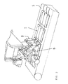
- Fig. 1 a side view of a connection-oriented loose composite of connectors and solar cells on a conveyor belt
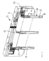
- Fig. 2 a perspective view of the device according to the invention with the gripping and storage devices for connector and solar cell
- Fig. 3 a perspective view of the stitching station
- Fig. 4 a perspective view of the delivery unit of the stitching station
- Fig. 5 a section through the stapling head in perspective view
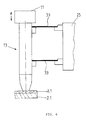
- Fig. 6 a schematic representation of a variant of the compensation system for the stapling pin.
- the Fig. 1 shows a solar cell string 1, which is composed of several juxtaposed solar cells 2.1 ... 2.n, which by solder 3.1, ... 3.n electrical to be connected.
- a first solar cell 2.1 is deposited by a gripping and depositing device 4 on a conveyor belt 5, which is moved intermittently, for example.
- a further gripping and depositing device 6 deposits a connector 3.1 on the upper side 7 of the first solar cell 2.1 and fixes it on the solar cell 2.1 to a stapling station 8 to be described later on the loose composite 9 of connector 3.1 and solar cell 2.1 for spot stapling has taken over by means of soldering in time with the gripping and storage device 6.
- the gripping and depositing device 4 deposits a second solar cell 2.2 onto the conveyor belt 5, which has continued to be driven in a cycle, so that the underside 10 of the second solar cell 2.2 comes to rest on the already laid connector 3.1.
- the gripping and depositing device 6 places the next connector 3.2 on the second solar cell 2.2, fixes it and transfers the loose composite 9 of connector 3.2 and solar cell 2.2 to the stapling station 8 for stapling the connector 3.1 to the upper side 4 of the solar cell 2.2.
- the juxtaposition of the solar cells 2.1, ... 2.n and stapling continues until the desired length of the solar cell string 1 is reached.
- the fixing by the gripping and contact device 6 and stapling by the stitching station 8 can also proceed so that the gripping and depositing device 6 releases the composite 9 only when the stapling process between the connector and the solar cell is completed.
- the Fig. 2 shows the device according to the invention in a perspective functional representation, in which there are on the conveyor belt 5, a number of juxtaposed solar cells 2.1 .... 2.3, with a not further shown supply device for the solar cells 2.1 ... 2.n, the gripping and storage device 4 (see also Fig.1 ) for the solar cell 2.1 ... 2.2, the gripping and depositing device 6 for the connectors 3.1 ... 3.n and the stitching station 8.
- stitching station 8 is composed of a feed unit 12 and a vertically deliverable with respect to the composite 9 stapling head 13, which are connected to each other by a snap closure 14, so that a simple and quick change of the stapling head 13 is ensured.
- the feed unit 12 is designed to produce a rapid feed movement of the stapling head 13 in relation to the loose composite 9 of connector 3.1,... 3.n and solar cell 2.1,.
- the fast feed movement is by a pneumatic cylinder 15 (see Fig. 4 ), which in an inclined position within the feed unit 12 about the cylinder rod 16 facing away from the end 17 is pivotally fixed to a housing wall 18 of the feed unit 12.
- the cylinder rod 16 of the pneumatic cylinder 15 is pivotally connected at the other end to an arm 19 of an angle lever 20.
- the other arm 21 of the angle lever 20 is pivotally mounted on a support 22 for the stapling head 13, wherein the angle lever 20 itself is rotatable about an axis 23 approximately symmetrically about the arms 23 and 23.
- the axis 23 is in alignment with the pivotable end 17 of the pneumatic cylinder 15.
- the angle lever 20 makes it possible, the fast feed movement in relation to the loose composite 9 of connector 3.1 ... 3.n and solar cell 2.1 ... 2 .n clearly Slow down to ensure a gentle placement of the stapling head 13 on the solar cell 2.1 ... 2.n.
- the carrier 22, on which the stapling head 13 is fixed with the quick release, is in two parallel to each other in the housing 12 of the feed unit parallel guides 24 in the direction of the composite 9 of connector 3.1 ... 3.n and solar cell 2.1 ... 2. n arranged displaceably, whereby the stapling head 13 assumes over its entire length relative to the composite 9 a horizontal position in the feed movement.
- the Fig. 5 shows a section of the stapling head 13.
- the stapling head 13 has a cuboid-shaped housing 25 which is fixed to a carrier 26 which is coupled via the quick release 14 with the carrier 22 of the feed unit 12.
- a carrier 26 which is coupled via the quick release 14 with the carrier 22 of the feed unit 12.
- guide bushings 27 are provided, in which stapling pins 28 are inserted, which are slidably disposed in the guide bush 27 against a compensation system in the form of a compression spring 29 to a corresponding pressure force when placing the stapling points 30 provided with stapling pins 28 on the composite 9 from connector 3.1, ... 3.n and solar cell 2.1, ... 2.n to produce.
- Each stitching pin 28 has its own heating cartridge 31 for generating the temperature required for stapling, which is monitored by an associated temperature sensor 32.
- the stapling tip 30 is designed as a wearing part and placed on the stapling pin 28 interchangeable, so that the stapling tip 30 can be easily changed without removing the stapling pin 28.
- the compensation system for applying a corresponding pressure force on the composite 9 of connector 3.1 ... 3.n and solar cell 2.1 ... 2.n can, like Fig. 6 also consists of at least two vertically superimposed leaf springs 33 which are fixed to the housing 25 of the stapling head 13, whereby a parallelogram between the housing 25, stapling pin 28 and the leaf springs 33 is formed, which ensures that the stapling tip 30 at its deflection moved parallel to the housing 25.
- the leaf springs 33 then take over both the function of the delivery force and the leadership function.
- the stapling head 13 is delivered vertically by a suitably designed feed unit 11. This makes it possible to exclude a sliding friction as a disturbance.
- the stitching heads 13 are each coupled individually suspended.
- the number of stitching heads 13 depends on the number of connectors 3.1,... 3.n, which are to be stapled with a solar cell. In other words, if, for example, three connectors arranged parallel to one another are required for connecting the solar cells, three stitching heads 13 each have to be provided spaced apart from the connectors (see also FIG Fig. 2 ).
- the process according to the invention proceeds as follows.
- the solar cell 2.1... 2.n and the connector 3.1... 3.n are each placed and held in sequence on the conveyor belt 5 by separate gripping and depositing devices 4 and 6 in a mutually loose composite 9.
- the connector 3.1 ... 3.n is then fixed in its storage position by lowering a held by the feed unit 12, under a spring force stitch tip 30 on the solar cell.
- Connector 3.1 ... 3.n and the Solar cell 2.1,2.n are then stapled together on the top side by soldering.
- the responsible for the connector gripping and storage device 6 releases the previously fixed storage position of the composite of connector and solar cell in tact as soon as the stapling begins or is completed.
- the gripping and storage device 6 moves back, picks up another connector from the feed unit for the next solar cell, positions and fixes the same again until the stapling station starts to staple or stapling is performed.
Landscapes
- Photovoltaic Devices (AREA)
Priority Applications (1)
| Application Number | Priority Date | Filing Date | Title |
|---|---|---|---|
| EP09008537A EP2273566A1 (fr) | 2009-06-30 | 2009-06-30 | Dispositif et procédé de fixation de position d'un assembleur par soudage sur une cellule solaire |
Applications Claiming Priority (1)
| Application Number | Priority Date | Filing Date | Title |
|---|---|---|---|
| EP09008537A EP2273566A1 (fr) | 2009-06-30 | 2009-06-30 | Dispositif et procédé de fixation de position d'un assembleur par soudage sur une cellule solaire |
Publications (1)
| Publication Number | Publication Date |
|---|---|
| EP2273566A1 true EP2273566A1 (fr) | 2011-01-12 |
Family
ID=41338665
Family Applications (1)
| Application Number | Title | Priority Date | Filing Date |
|---|---|---|---|
| EP09008537A Withdrawn EP2273566A1 (fr) | 2009-06-30 | 2009-06-30 | Dispositif et procédé de fixation de position d'un assembleur par soudage sur une cellule solaire |
Country Status (1)
| Country | Link |
|---|---|
| EP (1) | EP2273566A1 (fr) |
Cited By (1)
| Publication number | Priority date | Publication date | Assignee | Title |
|---|---|---|---|---|
| CN112490331A (zh) * | 2020-12-18 | 2021-03-12 | 无锡奥特维科技股份有限公司 | 抓取单元、抓取装置、电池串叠放设备及电池串叠放方法 |
Citations (5)
| Publication number | Priority date | Publication date | Assignee | Title |
|---|---|---|---|---|
| EP1291929A1 (fr) * | 2001-09-11 | 2003-03-12 | Strela Gmbh | Module de cellules solaire et méthode de fabrication |
| WO2003098704A1 (fr) * | 2002-05-21 | 2003-11-27 | Otb Group B.V. | Procede et poste de pose de languettes permettant de fixer des languettes sur une pile solaire, ainsi que procede et appareil permettant de fabriquer un panneau solaire |
| DE10297644T5 (de) | 2002-11-25 | 2005-10-06 | General Motors Corp. (N.D.Ges.D. Staates Delaware), Detroit | Vorrichtung und Verfahren zur Datenerfassung und -manipulation |
| EP1737048A1 (fr) * | 2004-03-31 | 2006-12-27 | Sanyo Electric Co., Ltd. | Procédé de fabrication de cellule solaire |
| DE102006007447A1 (de) | 2005-12-30 | 2007-07-12 | Teamtechnik Maschinen Und Anlagen Gmbh | Solarzellen-Verbindungsvorrichtung, Streifen-Niederhaltevorrichtung und Transportvorrichtung für eine Solarzellen-Verbindungsvorrichtung |
-
2009
- 2009-06-30 EP EP09008537A patent/EP2273566A1/fr not_active Withdrawn
Patent Citations (5)
| Publication number | Priority date | Publication date | Assignee | Title |
|---|---|---|---|---|
| EP1291929A1 (fr) * | 2001-09-11 | 2003-03-12 | Strela Gmbh | Module de cellules solaire et méthode de fabrication |
| WO2003098704A1 (fr) * | 2002-05-21 | 2003-11-27 | Otb Group B.V. | Procede et poste de pose de languettes permettant de fixer des languettes sur une pile solaire, ainsi que procede et appareil permettant de fabriquer un panneau solaire |
| DE10297644T5 (de) | 2002-11-25 | 2005-10-06 | General Motors Corp. (N.D.Ges.D. Staates Delaware), Detroit | Vorrichtung und Verfahren zur Datenerfassung und -manipulation |
| EP1737048A1 (fr) * | 2004-03-31 | 2006-12-27 | Sanyo Electric Co., Ltd. | Procédé de fabrication de cellule solaire |
| DE102006007447A1 (de) | 2005-12-30 | 2007-07-12 | Teamtechnik Maschinen Und Anlagen Gmbh | Solarzellen-Verbindungsvorrichtung, Streifen-Niederhaltevorrichtung und Transportvorrichtung für eine Solarzellen-Verbindungsvorrichtung |
Cited By (1)
| Publication number | Priority date | Publication date | Assignee | Title |
|---|---|---|---|---|
| CN112490331A (zh) * | 2020-12-18 | 2021-03-12 | 无锡奥特维科技股份有限公司 | 抓取单元、抓取装置、电池串叠放设备及电池串叠放方法 |
Similar Documents
| Publication | Publication Date | Title |
|---|---|---|
| EP2269757B1 (fr) | Appareil de brasage d'un connecteur et d'une cellule solaire avec une unité de nettoyage | |
| EP1974396B1 (fr) | Dispositif de mise en contact de cellules solaires, dispositif de maintien de bandes et dispositif de transport pour un dispositif de mise en contact de cellules solaires | |
| DE2704540C2 (fr) | ||
| DE102010003085B4 (de) | Vorrichtung und Verfahren zum Zuführen und Befestigen von Ausgleichselementen für den Unwuchtausgleich in einer Auswuchtmaschine | |
| EP0054775B1 (fr) | Dispositif de tri de bobines coniques | |
| DE2524315A1 (de) | Galvanisiergestell | |
| DE2460425B2 (de) | Vorrichtung zum Bewegen eines Drahtanschlußwerkzeuges gegenüber einem Halbleiterelement | |
| DE1591777B1 (de) | Vorrichtung zum einsetzen elektrischer bauelemente im schaltungstraeger | |
| DE2833307A1 (de) | Vorrichtung zum einsetzen von anschlussleitungen elektronischer bauteile | |
| DE3519970C2 (fr) | ||
| DE102006044748B4 (de) | Verfahren und Vorrichtung zur automatischen Montage von Dichtringen | |
| DE10163018B4 (de) | Vorrichtung zum fortlaufenden Ziehen von Langmaterial | |
| DE1101546B (de) | Vorrichtung zum Montieren elektrischer Schaltungselemente | |
| DE2337303B2 (de) | Automatische Verbindungsvorrichtung insbesondere zum Zusammenbau von Halbleiteranordnungen | |
| DE68912993T2 (de) | Verfahren und Vorrichtung zum Bewickeln zweipoliger Ständer von elektrischen Motoren. | |
| DE2007266A1 (de) | Einrichtung zum Befestigen von drahtförmigen Teilen auf einem Trägerteil mittels ültraschallschweißung | |
| EP2273566A1 (fr) | Dispositif et procédé de fixation de position d'un assembleur par soudage sur une cellule solaire | |
| DE102016109151B3 (de) | Verdrilleinrichtung | |
| CH689288A5 (de) | Verfahren und Vorrichtung zum Bestuecken von Steckergehaeusen. | |
| DE3240409C1 (de) | Naeheinrichtung mit einer Schleppklemme zum Halten von Stofflagenenden | |
| DE102006034492B4 (de) | Solarzellen-Verbindungsanlage | |
| DE102010028239A1 (de) | Kontaktiervorrichtung zum elektrischen Verschalten von Solarzellenreihen eines Solarmoduls | |
| DE69217677T2 (de) | Verfahren und einrichtung fuer die einfuehrung von drahtenden inbauelemente und herstellungseinrichtung von kabelbaeumen | |
| DE4002193A1 (de) | Verfahren zum bestuecken der gehaeusekammern von gehaeusen mit an elektrische leitungen gecrimten kontaktelementen sowie zusatzvorrichtung zur durchfuehrung des verfahrens fuer eine kontaktelemente an elektrische leitungen crimpende grundmaschine | |
| DE3126109C2 (fr) |
Legal Events
| Date | Code | Title | Description |
|---|---|---|---|
| PUAI | Public reference made under article 153(3) epc to a published international application that has entered the european phase |
Free format text: ORIGINAL CODE: 0009012 |
|
| AK | Designated contracting states |
Kind code of ref document: A1 Designated state(s): AT BE BG CH CY CZ DE DK EE ES FI FR GB GR HR HU IE IS IT LI LT LU LV MC MK MT NL NO PL PT RO SE SI SK TR |
|
| AX | Request for extension of the european patent |
Extension state: AL BA RS |
|
| 17P | Request for examination filed |
Effective date: 20110722 |
|
| RAP1 | Party data changed (applicant data changed or rights of an application transferred) |
Owner name: MIKRON BERLIN GMBH |
|
| STAA | Information on the status of an ep patent application or granted ep patent |
Free format text: STATUS: THE APPLICATION IS DEEMED TO BE WITHDRAWN |
|
| 18D | Application deemed to be withdrawn |
Effective date: 20160105 |