EP2273585B1 - Bloc-batteries - Google Patents
Bloc-batteries Download PDFInfo
- Publication number
- EP2273585B1 EP2273585B1 EP10251225.8A EP10251225A EP2273585B1 EP 2273585 B1 EP2273585 B1 EP 2273585B1 EP 10251225 A EP10251225 A EP 10251225A EP 2273585 B1 EP2273585 B1 EP 2273585B1
- Authority
- EP
- European Patent Office
- Prior art keywords
- bare cell
- protective circuit
- curved
- lead plate
- secondary battery
- Prior art date
- Legal status (The legal status is an assumption and is not a legal conclusion. Google has not performed a legal analysis and makes no representation as to the accuracy of the status listed.)
- Not-in-force
Links
Images

Classifications
-
- H—ELECTRICITY
- H01—ELECTRIC ELEMENTS
- H01M—PROCESSES OR MEANS, e.g. BATTERIES, FOR THE DIRECT CONVERSION OF CHEMICAL ENERGY INTO ELECTRICAL ENERGY
- H01M50/00—Constructional details or processes of manufacture of the non-active parts of electrochemical cells other than fuel cells, e.g. hybrid cells
- H01M50/50—Current conducting connections for cells or batteries
- H01M50/572—Means for preventing undesired use or discharge
-
- H—ELECTRICITY
- H01—ELECTRIC ELEMENTS
- H01M—PROCESSES OR MEANS, e.g. BATTERIES, FOR THE DIRECT CONVERSION OF CHEMICAL ENERGY INTO ELECTRICAL ENERGY
- H01M10/00—Secondary cells; Manufacture thereof
- H01M10/42—Methods or arrangements for servicing or maintenance of secondary cells or secondary half-cells
- H01M10/425—Structural combination with electronic components, e.g. electronic circuits integrated to the outside of the casing
-
- H—ELECTRICITY
- H01—ELECTRIC ELEMENTS
- H01M—PROCESSES OR MEANS, e.g. BATTERIES, FOR THE DIRECT CONVERSION OF CHEMICAL ENERGY INTO ELECTRICAL ENERGY
- H01M50/00—Constructional details or processes of manufacture of the non-active parts of electrochemical cells other than fuel cells, e.g. hybrid cells
- H01M50/20—Mountings; Secondary casings or frames; Racks, modules or packs; Suspension devices; Shock absorbers; Transport or carrying devices; Holders
-
- H—ELECTRICITY
- H01—ELECTRIC ELEMENTS
- H01M—PROCESSES OR MEANS, e.g. BATTERIES, FOR THE DIRECT CONVERSION OF CHEMICAL ENERGY INTO ELECTRICAL ENERGY
- H01M50/00—Constructional details or processes of manufacture of the non-active parts of electrochemical cells other than fuel cells, e.g. hybrid cells
- H01M50/50—Current conducting connections for cells or batteries
- H01M50/502—Interconnectors for connecting terminals of adjacent batteries; Interconnectors for connecting cells outside a battery casing
-
- H—ELECTRICITY
- H01—ELECTRIC ELEMENTS
- H01M—PROCESSES OR MEANS, e.g. BATTERIES, FOR THE DIRECT CONVERSION OF CHEMICAL ENERGY INTO ELECTRICAL ENERGY
- H01M50/00—Constructional details or processes of manufacture of the non-active parts of electrochemical cells other than fuel cells, e.g. hybrid cells
- H01M50/50—Current conducting connections for cells or batteries
- H01M50/528—Fixed electrical connections, i.e. not intended for disconnection
-
- H—ELECTRICITY
- H01—ELECTRIC ELEMENTS
- H01M—PROCESSES OR MEANS, e.g. BATTERIES, FOR THE DIRECT CONVERSION OF CHEMICAL ENERGY INTO ELECTRICAL ENERGY
- H01M50/00—Constructional details or processes of manufacture of the non-active parts of electrochemical cells other than fuel cells, e.g. hybrid cells
- H01M50/50—Current conducting connections for cells or batteries
- H01M50/528—Fixed electrical connections, i.e. not intended for disconnection
- H01M50/529—Intercell connections through partitions, e.g. in a battery casing
-
- H—ELECTRICITY
- H01—ELECTRIC ELEMENTS
- H01M—PROCESSES OR MEANS, e.g. BATTERIES, FOR THE DIRECT CONVERSION OF CHEMICAL ENERGY INTO ELECTRICAL ENERGY
- H01M2200/00—Safety devices for primary or secondary batteries
-
- H—ELECTRICITY
- H01—ELECTRIC ELEMENTS
- H01M—PROCESSES OR MEANS, e.g. BATTERIES, FOR THE DIRECT CONVERSION OF CHEMICAL ENERGY INTO ELECTRICAL ENERGY
- H01M2200/00—Safety devices for primary or secondary batteries
- H01M2200/10—Temperature sensitive devices
- H01M2200/106—PTC
-
- H—ELECTRICITY
- H01—ELECTRIC ELEMENTS
- H01M—PROCESSES OR MEANS, e.g. BATTERIES, FOR THE DIRECT CONVERSION OF CHEMICAL ENERGY INTO ELECTRICAL ENERGY
- H01M50/00—Constructional details or processes of manufacture of the non-active parts of electrochemical cells other than fuel cells, e.g. hybrid cells
- H01M50/50—Current conducting connections for cells or batteries
- H01M50/502—Interconnectors for connecting terminals of adjacent batteries; Interconnectors for connecting cells outside a battery casing
- H01M50/514—Methods for interconnecting adjacent batteries or cells
- H01M50/516—Methods for interconnecting adjacent batteries or cells by welding, soldering or brazing
-
- H—ELECTRICITY
- H01—ELECTRIC ELEMENTS
- H01M—PROCESSES OR MEANS, e.g. BATTERIES, FOR THE DIRECT CONVERSION OF CHEMICAL ENERGY INTO ELECTRICAL ENERGY
- H01M50/00—Constructional details or processes of manufacture of the non-active parts of electrochemical cells other than fuel cells, e.g. hybrid cells
- H01M50/50—Current conducting connections for cells or batteries
- H01M50/572—Means for preventing undesired use or discharge
- H01M50/574—Devices or arrangements for the interruption of current
- H01M50/583—Devices or arrangements for the interruption of current in response to current, e.g. fuses
-
- Y—GENERAL TAGGING OF NEW TECHNOLOGICAL DEVELOPMENTS; GENERAL TAGGING OF CROSS-SECTIONAL TECHNOLOGIES SPANNING OVER SEVERAL SECTIONS OF THE IPC; TECHNICAL SUBJECTS COVERED BY FORMER USPC CROSS-REFERENCE ART COLLECTIONS [XRACs] AND DIGESTS
- Y02—TECHNOLOGIES OR APPLICATIONS FOR MITIGATION OR ADAPTATION AGAINST CLIMATE CHANGE
- Y02E—REDUCTION OF GREENHOUSE GAS [GHG] EMISSIONS, RELATED TO ENERGY GENERATION, TRANSMISSION OR DISTRIBUTION
- Y02E60/00—Enabling technologies; Technologies with a potential or indirect contribution to GHG emissions mitigation
- Y02E60/10—Energy storage using batteries
Definitions
- Embodiments relate to a battery pack of a chargeable and dischargeable secondary battery.
- a battery pack of a chargeable and dischargeable secondary battery includes a bare cell having a case in which an electrode assembly is accommodated and a protective circuit module (PCM) connecting the bare cell to an external terminal to control charge and discharge of the bare cell.
- PCM protective circuit module
- a lamination type electrode assembly obtained by laminating a positive electrode plate, a negative electrode plate, and a separator interposed between the positive electrode plate and the negative electrode plate can be used as the electrode assembly of the bare cell.
- a wind type electrode assembly wound in a state where the positive electrode plate, the negative electrode plate, and the separator interposed between the positive electrode plate and the negative electrode plate are laminated can be used as the electrode assembly of the bare cell.
- the electrode assembly of such a battery pack can be accommodated in a cylindrical or polygonal can or a pouch type armoring material to form the bare cell.
- the bare cell is electrically connected to the PCM.
- a supporting member can be installed to electrically connect the bare cell to the PCM and to mechanically support the PCM installed in the bare cell.
- a supporting holder is installed as the supporting member. Molding resin is injected into and filled in a gap formed between the bare cell and the protective circuit module in a hot melting process to form the supporting member. The protective circuit module is supported by the molding resin.
- the protective circuit module When the molding resin as the supporting member is injected in a hot melting process, due to an inferior formation of the molding resin, the protective circuit module can be inclined in the vertical direction or twisted laterally. When the protective circuit module is vertically inclined in this way, it can cause the external terminal of the protective circuit module to not be connected to an external device. When the protective circuit module is twisted laterally, the external terminal of the protective circuit module can deviate from an initial position so that assembly is not completed.
- US2009104513 discloses a conductive tab that includes a battery connecting part contacting a plurality of secondary batteries, a wire connecting part extended from the battery connecting part and connected to a wire, and at least one bending part formed in the battery connecting part. The bending part is coupled to the secondary battery to guide the positions of the secondary batteries.
- US 2009/0087734 discloses a secondary battery having positive and negative terminals formed on the top face of a unit cell and positive and negative terminals formed on a surface of a circuit board opposed to the unit cell. These are electrically connected to each other by connectors which include an elastic body and a conductor.
- JP 2002-100331 discloses a battery pack having a plurality of cylindrical secondary batteries and a circuit board formed in a space between curved faces of adjacent cylindrical batteries.
- US 2009/111018 discloses a battery pack including a rechargeable battery having at least one rounded lateral side and a cover frame including a frame surrounding each of the lateral sides of the battery.
- the present invention provides a battery pack of a chargeable and dischargeable secondary battery.
- the invention is defined in claim 1.
- lead plates which electrically connect a protective circuit module to a bare cell, support the protective circuit module.
- Surfaces of the lead plates contacting the bare cell have the same shape as that of one side of the bare cell.
- the lead plates When one side of the bare cell has a curvature, the lead plates have curvature pieces to be seated on the side of the bare cell. Therefore, the lead plates are closely attached to the bare cell with a large area than the bare cell so that the protective circuit module is supported more stably.
- the lead plates electrically connecting the protective circuit module to the bare cell support the protective circuit module.
- the lead plates can have the same height as that of the protective circuit element provided in the protective circuit module.
- the protective circuit element may be mounted in the center of one side of the protective circuit module facing the bare cell to support the protective circuit module. Therefore, both sides of the protective circuit module are supported by the lead plates and the center of the protective circuit module is supported by the protective circuit element.
- the curved portions of the first and second lead plates enable the first and second lead plates to stably support the protective circuit module on the curved surface of the bare cell.
- the curved portions of the first and second lead plates can conform to the shape of the curved surface of the bare cell. In some embodiments, all the portions of the first and second lead plates can conform to the shape of the adjacent portions of the bare cell.
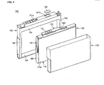
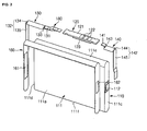
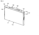
- a battery pack 100 includes a bare cell 110, and a protective circuit module 120 electrically connected to the bare cell 110.
- the protective circuit module 120 can control the charge and discharge of the bare cell 110.
- a first lead plate 130 and a second lead plate 140 are also provided.
- the first and second lead plates 130, 140 act to support the protective circuit module 120 and to electrically connect the bare cell 110 to the protective circuit module 120.
- a cover 150 surrounding the bare cell 110 and the protective circuit module 120 is also provided.
- the surfaces of the first and second lead plates 130 and 140 which are seated on the bare cell 110 have the same shape as those of the surfaces that contact the bare cell 110.
- the surfaces of the first and second lead plates 130 and 140 that contact the bare cell 110 conform to the shape of the bare cell 110.
- the battery pack 100 further includes an insulation member 160 disposed between the first lead plate 130 and the second lead plate 140 to insulate them from each other, and a label 170 for fixing the bare cell 110 and the cover 150.
- the bare cell 110 is produced by accommodating an electrode assembly (not shown) in a can 111 made of a metal.
- the can 111 may be made of aluminum or an alloy of aluminum, but embodiments of the invention are not limited thereto.
- the can 111 may be made out of any suitable material.
- the can 111 is a polygonal can having an approximately rectangular parallelepiped. In other embodiments, the can could have other appropriate shapes.
- the can 111 includes first and second rectangular surfaces 111a and 111b that are wide rectangular surfaces. Third, fourth, fifth, and sixth surfaces 111c, 111d, 111e, and 111f integrated with the first and second surfaces 111a and 111b are narrow rectangular surfaces. The third and fourth surfaces 111c and 111d are short in length. The fifth and sixth surfaces 111e and 111f are longer than the third and fourth surfaces 111c and 111d. In other words, in this embodiment, first and second rectangular surfaces 111a and 111b are the major surfaces of the rectangular parallelepiped shaped can 111. The third and fourth surfaces 111c and 111d can be considered to be end surfaces. In this embodiment, the fifth and sixth surfaces 111e and 111f are curved, as will be discussed below. In other embodiments, only one of the fifth and sixth surfaces 111e and 111f may be curved.
- the electrode assembly includes a positive electrode plate (not shown), a negative electrode plate (not shown), and a separator (not shown) interposed between the positive electrode plate and the negative electrode plate, which is the structure of a common electrode assembly.
- the positive electrode plate is electrically connected to the can 111
- the negative electrode plate is electrically connected to an electrode terminal 112 that protrudes from the third surface 111c of the bare cell 110.
- the protective circuit module 120 includes a protective circuit board 121. External terminals 122 are mounted on one surface of the protective circuit board 121 (the surface facing away from the bare cell 110 in this embodiment).
- the protective circuit board 121 includes a protective circuit element 123 provided on the other surface of the protective circuit board 121. Therefore, in this embodiment, the external terminals 122 and the protective circuit element 123 face in different directions.
- the protective circuit element 123 controls the charge and discharge of the bare cell 110.
- the protective circuit element 123 makes the charge state of the bare cell 110 uniform and prevents overcharge and overdischarge.
- the protective circuit board 121 includes a positive electrode connection terminal (not shown) and a negative electrode connection terminal (not shown) that are electrically connected to the positive electrode terminal and the negative electrode terminal of the bare cell 110, respectively.
- the first lead plate 130 electrically connects the positive electrode terminal of the bare cell 110 to the positive electrode connection terminal of the protective circuit board 121.
- the second lead plate 140 electrically connects the negative electrode terminal of the bare cell 110 to the negative electrode connection terminal of the protective circuit board 121.
- the first and second lead plates 130 and 140 may be made of any electric conductive material.
- the first and second lead plates 130 and 140 may be made of nickel or a nickel alloy. However, embodiments of the present invention need not be limited to the above.
- first and second lead plates 130 and 140 in this embodiment will now be described.
- the first lead plate 130 includes a board connection unit 131 formed on one end of the lead plate 130.
- the board connection unit 131 is connected to the positive electrode connection terminal of the protective circuit board 121 and to a bare cell connection unit 132.
- the bare cell connection unit 132 is connected to the fourth surface 111d of the can 111 that corresponds to the positive electrode terminal of the bare cell 110.
- the first lead plate 130 further includes connection unit 133 provided to connect the board connection unit 131 to the bare cell connection unit 132.
- the board connection unit 131 is arranged to be parallel with the protective circuit board 121 and is electrically connected to the positive electrode connection terminal of the protective circuit board 121 by welding or the like.
- the bare cell connection unit 132 has the shape matching the shape of the fifth surface 111e of the bare cell 110 including the can 111.
- the fifth surface 111e of the can 111 has a rounded shape with a curvature in this embodiment.
- the bare cell connection unit 132 includes a curvature piece 134 having the same or a similar curvature as that of the curvature of the adjacent portion of the fifth surface 111e.
- the bare cell connection unit 132 further includes a connector 135 arranged (e.g. bent) at a right angle from the curvature piece 134 to be connected to the fourth surface 111d of the can 111.
- the curvature piece 134 may have a larger width than that of the connector 135 so that the area that supports the protective circuit board 121 increases.
- the connector 135 is connected to the fourth surface 111d of the can 111 through a first through hole 161 of the insulation member 160.
- connection unit 133 is provided at the end of the board connection unit 131 and is arranged perpendicular to one end of the curvature piece 134 that is one side of the bare cell connection unit 132 in order to connect the board connection unit 131 to the bare cell connection unit 132.
- a secondary protective element may be provided between the first lead plate 130 and the protective circuit module 120.
- a positive temperature coefficient (PTC) element 180 or a safety element having equivalent performance is provided as the secondary protective element.
- the PTC element 180 is used as the secondary protective element.
- a thermal fuse may be used as the secondary protective element.
- a secondary protective element may not be provided.
- the second lead plate 140 includes a board connection unit 141 provided at one end of the second lead plate 140.
- the board connection unit 141 is connected to the negative electrode connection terminal of the protective circuit board 121 and to a bare cell connection unit 142.
- the bare cell connection unit 142 is connected to the electrode terminal 112 of the third surface 111c of the can 111 corresponding to the negative electrode terminal of the bare cell 110.
- the second lead plate 140 further includes a connection unit 143 connecting the board connection unit 141 to the bare cell connection unit 142.
- the board connection unit 141 is arranged to be parallel with the protective circuit board 121 and is electrically connected to the negative electrode connection terminal of the protective circuit board 121 by welding or the like.
- the bare cell connection unit 142 has the shape matching the shape of the fifth surface 111e of the bare cell 110 including the can 111.
- the bare cell connection unit 142 includes a curvature piece 144 having the same or a similar curvature as that of the adjacent portion of the fifth surface 111e of the can 111, and a connector 145.
- the connector 145 is arranged (e.g. bent) at a right angle from the curvature piece 144 to be connected to the electrode terminal 112 that protrudes from the third surface 111c of the can 111.
- the curvature piece 144 may have a larger width than the connection unit 145.
- the curvature piece 144 may have a relatively large contact area with the fifth surface 111e so that the area of the curvature piece 144 that supports the protective circuit board 121 increases.
- the connector 145 is connected to the electrode terminal 112 of the third surface 111c of the can 111 through a second through hole 162 of the insulation member 160. That is, although the width of the connector 145 is smaller than the width of the curvature piece 144 in this embodiment, other embodiments could use other widths.
- the connector 145 could have any width that enables the connector 145 to be electrically connected to the electrode terminal 112 of the third surface 111c by welding or the like.
- connection unit 143 Both ends of the connection unit 143 are perpendicular to the board connection unit 141 and the bare cell connection unit 142 in this embodiment.
- the cover 150 When installed, the cover 150 surrounds the bare cell 110, the protective circuit module 120, and the first and second lead plates 130 and 140.
- the cover 150 includes four frames 151, 152, 153, and 154 integrated with each other.
- the first frame 151 corresponds to the fifth surface 111e of the bare cell 110.
- the first frame 151 surrounds the protective circuit module 120.
- the first frame 151 has a plurality of terminal holes 151 a, through which the external terminals 122 of the protective circuit module 120 protrude.
- the first frame 151 has a water-sensitive label attaching groove 151 b, to which a water-sensitive label 190 can be attached.
- the second frame 152 is formed at one end of the first frame 151 and is integrated with the first frame 151.
- the third frame 153 is formed at the other end of the first frame 151 and is integrated with the first frame 151.
- the second frame 152 corresponds to the third surface 111c of the can 111 (i.e. one of the end surfaces in this embodiment) and the third frame 153 corresponds to the fourth surface 111d of the can 111 (i.e. the other end surfaces in this embodiment) so that the third and fourth surfaces 111c and 111d of the can 111 are protected.
- Both ends of the fourth frame 154 are integrated with the ends of the second frame 152 and the third frame 153. Therefore, the fourth frame 154 corresponds to the fourth surface 111d of the can 111 so as to protect the fourth surface 111d of the can 111.
- the insulation member 160 is attached to the third surface 111c, the fourth surface 111d, and the fifth surface 111e of the can 111.
- the insulation member 160 insulates the protective circuit element 123 of the protective circuit module 120 mounted on the fourth surface 111d from the can 111 of the bare cell 110.
- the insulation member 160 insulates the first lead plate 130 mounted on the fourth surface 111d and the second lead plate 140 mounted on the third surface 111c from the can 111 of the bare cell 110.
- the insulation member 160 has a first through hole 161 formed on one side (corresponding to the fourth surface 111d in this embodiment) and a second through hole 162 formed in the other side (corresponding to the third surface 111c in this embodiment).
- the connector 135 of the first lead plate 130 is connected to the fourth surface 111d corresponding to the positive electrode of the bare cell 110 through the first through hole 161.
- the connector 145 of the second lead plate 140 is connected to the electrode terminal 112 corresponding to the negative electrode of the bare cell 110 through the second through hole 162.
- a tape made of an insulation material or any member having the same property, material, and shape as the tape may be used as the insulation member 160 in other embodiments.
- the insulation member 160 could also take other appropriate shapes.
- the label 170 surrounds the sides and the bottom of the bare cell 110 after the bare cell 110 has been coupled with the cover 150.
- a portion of the first lead plate that is located adjacent a first portion of a curved surface of the bare cell is curved
- a portion of the second lead plate that is located adjacent a second portion of the curved surface of the bare cell is curved.
- the portion of the first lead plate that is located adjacent the first portion of the curved surface of the bare cell is curved with substantially a same curvature as a curvature of the first portion of the curved surface
- the portion of the second lead plate that is located adjacent the second portion of the curved surface of the bare cell is curved with substantially a same curvature as a curvature of the second portion of the curved surface.
- the curved surface 111e of the bare cell in this embodiment has a uniform curvature
- the surface 111e of the bare cell in other embodiments may have a non-uniform curvature.
- a first portion of curved surface of the bare cell may be curved with a first curvature and a second portion of curved surface of the bare cell may be curved with a second curvature.
- the portion of the first lead plate that is located adjacent the first portion of the curved surface may have a different curvature to the portion of the second lead plate that is located adjacent the second portion of a curved surface.
- the first lead plate 130 and the second lead plate 140 are first assembled on the protective circuit board 121 of the protective circuit module 120. That is, the board connection unit 131 of the first lead plate 130 may be welded to the positive electrode connection terminal (not shown) of the protective circuit board 121.
- the PTC element 180 is mounted between the first lead plate 130 and the protective circuit board 121. Therefore, the board connection unit 131 of the first lead plate 130 is connected to one end of the PTC element 180. The other end of the PTC element 180 is connected to the positive electrode connection terminal of the protective circuit board 121.
- the negative electrode connection terminal (not shown) of the protective circuit board 121 is welded to the board connection unit 141 of the second lead plate 140.
- first and second lead plates 130 and 140 are electrically connected to the bare cell 110.
- the insulation member 160 is attached to the external surface of the bare cell 110.
- the insulation member 160 is attached to the third, fourth, and fifth surfaces 111c, 111d, and 111e of the can 111, to which the first and second lead plates 130 and 140 are attached.
- the protective circuit module 120 to which the first and second lead plates 130 and 140 are connected, may be seated on the narrow and relatively long fifth or sixth surface 111e or 111f among the sides of the can 111 of the bare cell 110.
- the protective circuit module 120 is seated on the fifth surface 111e, which is curved.
- the protective circuit module 120 is seated such that the first and second lead plates 130 and 140 are electrically connected to mechanically support the protective circuit module 120.
- the curvature piece 134 of the bare cell connection unit 132 of the first lead plate 130 is seated on the fifth surface 111e.
- the connector 135 is then welded to the fourth surface 111d in this embodiment. Therefore, the first lead plate 130 is electrically connected to the positive electrode of the bare cell 110 by the connector 135.
- the first lead plate 130 mechanically supports the protective circuit board 121 as a result of the curvature piece 134.
- the curvature piece 134 has approximately the same curvature as that of the fifth surface 111e so that it is closely attached to the fifth surface 111e.
- the first lead plate stably supports the protective circuit module 120.
- the curvature piece 134 also has a large width, which also helps to support the protective circuit module 120.
- the curvature piece 144 of the bare cell connection unit 142 of the second lead plate 140 is seated on the fifth surface 111e.
- the connector 145 is then welded to the electrode terminal 112 as a negative electrode terminal that protrudes from the third surface 111e. Therefore, the second lead plate 140 is electrically connected to the negative electrode of the bare cell 110 by the connector 145.
- the second lead plate 140 mechanically and stably supports the protective circuit board 121 as a result of the curvature piece 144.
- the curvature piece 144 has approximately the same curvature as that of the fifth surface 111e so that it is closely attached to the fifth surface 111e.
- the second lead plate stably supports the protective circuit module 120.
- the curvature piece 144 also has a large width, which also helps to support the protective circuit module 120.
- the curvature pieces 134 and 144 of the first and second lead plates 130 and 140 have the same curvature as that of the fifth surface 111e of the bare cell 110 and have a relatively large width. Therefore, the curvature pieces 134 and 144 have a large area and are attached to the fifth surface 111e of the bare cell 110. Therefore, the protective circuit board 121 is supported by the first and second lead plates 130 and 140 as stable as possible. In other embodiments, the curvature pieces 134 and 144 need not have a larger width that the connectors 135, 145.
- the cover 150 is put on around the protective circuit module 120 and the bare cell 110.
- the first frame 151 of the cover 150 surrounds parts of the protective circuit module 120 and the first and second lead plates 130 and 140.
- the external terminals 122 of the protective circuit module 120 protrude through the terminal holes 151 a formed in the first frame 151.
- the remaining parts of the first and second lead plates 130 and 140 are surrounded by the second and third frames 152 and 153.
- the fourth frame 154 surrounds the sixth surface 111f of the bare cell 110.
- the bare cell 110 and the cover 150 are surrounded by the label 170.
- the cover 150 is prevented from being separated from the bare cell 110 by the label 170.
- the water-sensitive label 190 is then attached to the first frame 151 of the cover 150.
- the first and second lead plates 130 and 140 have the same curvature as that of one surface of the bare cell 110 to be attached thereto to support the protective circuit module 120 including the protective circuit board 121.
- the first and second lead plates 130 and 140 electrically connect the bare cell 110 to the protective circuit module 120 and mechanically support the protective circuit module 120. Therefore, a separate support is not required. Therefore, if an external shock is applied thereto, the protective circuit module 120 is stably supported by the first and second lead plates 130 and 140.
- first and second lead plates 130 and 140 support the protective circuit module 120.
- the first and second lead plates 130 and 140 include board connection units 131 and 141, bare cell connection units 132 and 142, and connection units 133 and 143 for connecting the board connection units 131 and 141 to the bare cell connection units 132 and 142.
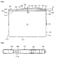
- the height h of the connection units 133 and 143 is equal to the height h1 of the protective circuit element 123 mounted on the protective circuit board 121.
- the protective circuit element 123 is mounted in the center of the protective circuit board 121, but it could be mounted differently in other embodiments.
- the protective circuit element 123 is mounted on an opposite surface of the protective circuit module 120 to the surface, on which the external terminals 122 of the protective circuit board 121 are mounted. Therefore, the protective circuit element 123 faces a surface of the bare cell 110 in this embodiment.
- the protective circuit element 123 may support the protective circuit module 120 including the protective circuit board 121.
- the protective circuit element 123 has a height of about 1.0 mm.
- the first and second lead plates 130 and 140 and the protective circuit element 123 may support the protective circuit board 121 together. Therefore, the protective circuit board 121 may be stably supported by one surface of the bare cell 110.
- the protective circuit element 123 may be mounted approximately in the center of one surface of the protective circuit board 121. Therefore, the protective circuit board 121 is supported by the protective circuit element 123 to prevent from being bent at the center.
- the curvature units 134 and 144 of the first and second lead plates 130 and 140 may have an area of at least 20% of the area of the fifth surface 111e.
- the area of the fifth surface 111e is 312,149 mm 2
- the area of the curvature piece 134 of the first lead plate 130 is 40,744 mm 2
- the area of the curvature piece 144 of the second lead plate 140 is 20,7696 mm 2 . Therefore, the areas of the curvature pieces 134 and 144 of the first and second lead plates 130 and 140 is about 19.7% of the area of the fifth surface 111e in this embodiment.
- the first and second lead plates are mainly connected to the bare cell by welding, but embodiments of the invention are not limited thereto. That is, the first and second lead plates may be fixed to the bare cell with an adhesive. The first and second lead plates may also be fixed to the bare cell with a tape.
- the center of the protective circuit board is supported by the protective circuit element so as to prevent the protective circuit board from being bent.
- the first and second lead plates are attached to one surface of the bare cell to support both ends of the protective circuit board.
- a protective circuit module electrically is connected to a bare cell through first and second lead plates.
- the protective circuit module is located adjacent a curved surface of the bare cell.
- a portion of the first lead plate that is located adjacent a first portion of the curved surface of the bare cell is curved, and a portion of the second lead plate that is located adjacent a second portion of the curved surface of the bare cell is curved.
- the curved portions of the first and second lead plates enable the first and second lead plates to stably support the protective circuit module on the curved surface of the bare cell.
- the portion of the first lead plate that is located adjacent the first portion of the curved surface of the bare cell is curved with substantially a same curvature as a curvature of the first portion of the curved surface
- the portion of the second lead plate that is located adjacent the second portion of the curved surface of the bare cell is curved with substantially a same curvature as a curvature of the second portion of the curved surface.
- the curved portions of the first and second lead plates can conform to the shape of the curved surface of the bare cell. In some embodiments, all the portions of the first and second lead plates can conform to the shape of the adjacent portions of the bare cell.
- the protective circuit module including the protective circuit board may be stably supported by the first and second lead plates so that fabrication costs spent in mounting a separated support is reduced and that assembling processes are simplified.
Landscapes
- Chemical & Material Sciences (AREA)
- Chemical Kinetics & Catalysis (AREA)
- Electrochemistry (AREA)
- General Chemical & Material Sciences (AREA)
- Engineering & Computer Science (AREA)
- Microelectronics & Electronic Packaging (AREA)
- Manufacturing & Machinery (AREA)
- Battery Mounting, Suspending (AREA)
- Connection Of Batteries Or Terminals (AREA)
Claims (13)
- Batterie secondaire, comprenant :une cellule nue (110) présentant une forme allongée et présentant :des première et deuxième surfaces terminales situées au niveau d'extrémités opposées respectives de la cellule nue (110) ;une surface courbe raccordant les première et deuxième surfaces terminales ;une première surface latérale ;une deuxième surface latérale située à l'opposé de la première surface latérale ; etune troisième surface située à l'opposé de la surface courbe ;dans laquelle la première surface latérale, la deuxième surface latérale et la troisième surface raccordent également la première surface terminale à la deuxième surface terminale ;la batterie comprenant en outre :un module de circuit de protection (120) raccordé électriquement à la cellule nue (110) par l'intermédiaire de première et deuxième plaques de plomb (130, 140), le module de circuit de protection (120) étant situé adjacent à la surface courbe de la cellule nue (110) ;dans laquelle la première plaque de plomb (130) est agencée de manière à raccorder le module de circuit de protection (120) à la première surface terminale de la cellule nue (110), et la deuxième plaque de plomb (140) est agencée de manière à raccorder le module de circuit de protection (120) à une borne d'électrode agencée sur la deuxième surface terminale de la cellule nue (110) ;caractérisée en ce qu'une partie de la première plaque de plomb (130) qui est située adjacente à une première partie de la surface courbe de la cellule nue (110) est courbe, et une partie de la deuxième plaque de plomb (140) qui est située adjacente à une deuxième partie de la surface courbe de la cellule nue (110) est courbe.
- Batterie secondaire selon la revendication 1, dans laquelle la partie de la première plaque de plomb (130) qui est située adjacente à la première partie de la surface courbe de la cellule nue (110) est courbe avec essentiellement une même courbure qu'une courbure de la première partie de la surface courbe, et la partie de la deuxième plaque de plomb (140) qui est située adjacente à la deuxième partie de la surface courbe de la cellule nue (110) est courbe avec essentiellement une même courbure qu'une courbure de la deuxième partie de la surface courbe.
- Batterie secondaire selon la revendication 1 ou 2, dans laquelle les première et deuxième plaques de plomb (130, 140) sont agencées de telle manière que toutes les parties des première et deuxième plaques de plomb (130, 140) qui sont des parties adjacentes de la cellule nue (110) présentent essentiellement une même forme que les parties adjacentes de la cellule nue (110).
- Batterie secondaire selon l'une quelconque des revendications précédentes, dans laquelle la première surface latérale et la deuxième surface latérale présentent des surfaces spécifiques qui sont supérieures à la surface courbe ou à la troisième surface.
- Batterie secondaire selon l'une quelconque des revendications précédentes, dans laquelle la troisième surface est courbe avec une courbure correspondant à celle de la surface courbe.
- Batterie secondaire selon l'une quelconque des revendications précédentes, dans laquelle les première et deuxième surfaces terminales sont essentiellement plates.
- Batterie secondaire selon l'une quelconque des revendications précédentes,
dans laquelle la première plaque de plomb (130) comprend une première partie couplage qui est raccordée à la première surface terminale de la cellule nue (110), et une première partie courbe qui s'étend à partir de la première partie couplage le long de la surface courbe de la cellule nue (110) afin d'être raccordée électriquement à une première borne de raccordement du module de circuit de protection (120) ; et
dans laquelle la deuxième plaque de plomb (140) comprend une deuxième partie couplage qui est raccordée à la borne d'électrode, et une deuxième partie courbe qui s'étend à partir de la deuxième partie couplage le long de la surface courbe de la cellule nue (110) afin d'être raccordée électriquement à une deuxième borne de raccordement du module de circuit de protection (120). - Batterie secondaire selon la revendication 7, dans laquelle :la première partie couplage est agencée adjacente à une partie de la première surface terminale de la cellule nue (110), la première partie couplage présentant une forme qui correspond à celle de la partie adjacente de la première surface terminale ; etla deuxième partie couplage est agencée adjacente à une partie de la deuxième surface terminale de la cellule nue (110), la deuxième partie couplage présentant une forme qui correspond à celle de la partie adjacente de la deuxième surface terminale.
- Batterie secondaire selon la revendication 7 ou 8, dans laquelle la première partie courbe présente une largeur supérieure à celle de la première partie couplage, et la deuxième partie courbe présente une largeur supérieure à celle de la deuxième partie couplage.
- Batterie secondaire selon l'une quelconque des revendications précédentes, dans laquelle le module du circuit de protection (120) comprend une carte de circuit de protection (121), et au moins une borne externe montée sur une surface extérieure de la carte de circuit de protection (121) ;
dans laquelle la carte du circuit de protection (121) comprend un élément de circuit de protection monté sur une surface intérieure de module de circuit de protection faisant face à la cellule nue (110). - Batterie secondaire selon la revendication 10 lorsqu'elle dépend de l'une quelconque des revendications 7 à 9 ;
dans laquelle la première plaque de plomb (130) comprend une première partie raccordement raccordant la première partie courbe à la carte de circuit de protection, la première partie raccordement faisant saillie sur une première hauteur à partir de la surface courbe ;
dans laquelle la première hauteur est essentiellement égale à une hauteur de l'élément de circuit de protection monté sur la carte de circuit de protection (121). - Batterie secondaire selon la revendication 10 ou 11 lorsqu'elle dépend de l'une quelconque des revendications 7 à 9 ;
dans laquelle la deuxième plaque de plomb (140) comprend une deuxième partie raccordement raccordant la deuxième partie courbe à la carte de circuit de protection (121), la deuxième partie raccordement faisant saillie sur une deuxième hauteur à partir de la surface courbe ;
dans laquelle la deuxième hauteur est essentiellement égale à une hauteur maximale de l'élément de circuit de protection monté sur la carte de circuit de protection. - Batterie secondaire selon la revendication 3 ou l'une quelconque des revendications dépendantes de la revendication 3, dans laquelle la batterie secondaire comprend en outre un élément isolant agencé pour entourer partiellement la cellule nue (110) ;
dans laquelle l'élément isolant est agencé de telle manière que la première plaque de plomb (130) vient en contact avec la première surface terminale de la cellule nue (110) via un premier trou dans l'élément isolant, et est électriquement isolé des autres surfaces de la cellule nue ;
dans laquelle l'élément isolant est agencé de telle manière que la deuxième plaque de plomb (140) vient en contact avec la borne d'électrode via un deuxième trou dans l'élément isolant, et est électriquement isolé des autres surfaces de la cellule nue (110) y compris la deuxième surface terminale.
Applications Claiming Priority (2)
| Application Number | Priority Date | Filing Date | Title |
|---|---|---|---|
| US22386209P | 2009-07-08 | 2009-07-08 | |
| US12/783,513 US9088042B2 (en) | 2009-07-08 | 2010-05-19 | Battery pack having elongate curved lead plates |
Publications (2)
| Publication Number | Publication Date |
|---|---|
| EP2273585A1 EP2273585A1 (fr) | 2011-01-12 |
| EP2273585B1 true EP2273585B1 (fr) | 2015-11-25 |
Family
ID=42711989
Family Applications (1)
| Application Number | Title | Priority Date | Filing Date |
|---|---|---|---|
| EP10251225.8A Not-in-force EP2273585B1 (fr) | 2009-07-08 | 2010-07-08 | Bloc-batteries |
Country Status (5)
| Country | Link |
|---|---|
| US (1) | US9088042B2 (fr) |
| EP (1) | EP2273585B1 (fr) |
| JP (1) | JP5197684B2 (fr) |
| KR (1) | KR101136313B1 (fr) |
| CN (1) | CN101950813A (fr) |
Families Citing this family (8)
| Publication number | Priority date | Publication date | Assignee | Title |
|---|---|---|---|---|
| KR101264741B1 (ko) * | 2012-03-05 | 2013-05-14 | 삼성에스디아이 주식회사 | 전류차단소자 및 이를 구비한 이차 전지 |
| KR101397025B1 (ko) * | 2012-09-10 | 2014-05-21 | 삼성에스디아이 주식회사 | 리드탭 조립체 및 이를 구비한 전지 모듈 |
| KR101440890B1 (ko) * | 2013-01-29 | 2014-09-18 | 삼성에스디아이 주식회사 | 전지 팩 |
| CN107093695B (zh) * | 2017-04-10 | 2020-09-11 | 上海电气集团股份有限公司 | 并联电池组 |
| CN109119709B (zh) * | 2017-06-22 | 2021-06-29 | 北京小米移动软件有限公司 | 电子设备 |
| US20210091360A1 (en) * | 2019-09-25 | 2021-03-25 | Apple Inc. | Battery pack with attached system module |
| CN114792867B (zh) * | 2021-01-26 | 2023-12-15 | 南京泉峰科技有限公司 | 电池包 |
| KR20260040841A (ko) * | 2024-09-19 | 2026-03-26 | 삼성에스디아이 주식회사 | 배터리 어셈블리 및 배터리 구동 장치 |
Citations (2)
| Publication number | Priority date | Publication date | Assignee | Title |
|---|---|---|---|---|
| JP2002100331A (ja) * | 2000-09-26 | 2002-04-05 | Nec Mobile Energy Kk | 電池パック |
| US20090111018A1 (en) * | 2007-10-30 | 2009-04-30 | Samsung Sdi Co., Ltd. | Battery pack |
Family Cites Families (11)
| Publication number | Priority date | Publication date | Assignee | Title |
|---|---|---|---|---|
| JP3696559B2 (ja) * | 2002-02-26 | 2005-09-21 | 京セラ株式会社 | バッテリー |
| KR100590006B1 (ko) * | 2004-06-23 | 2006-06-14 | 삼성에스디아이 주식회사 | 이차 전지와 이에 사용되는 전극 조립체 |
| JP4716719B2 (ja) | 2004-12-03 | 2011-07-06 | 三洋電機株式会社 | 電池パック |
| KR20070067783A (ko) | 2005-12-23 | 2007-06-29 | 삼성에스디아이 주식회사 | 이차전지 |
| JP5300187B2 (ja) * | 2006-09-07 | 2013-09-25 | 三洋電機株式会社 | 磁気誘導作用で充電されるパック電池 |
| KR101329830B1 (ko) | 2006-10-24 | 2013-11-14 | 삼성에스디아이 주식회사 | 이차 전지 |
| KR100770106B1 (ko) * | 2006-10-24 | 2007-10-24 | 삼성에스디아이 주식회사 | 리튬 이차 전지 |
| KR100890327B1 (ko) * | 2007-08-31 | 2009-03-26 | 삼성에스디아이 주식회사 | 도전성 탭 및 이를 갖는 전지 팩 |
| JP5077939B2 (ja) * | 2007-09-27 | 2012-11-21 | 日立マクセルエナジー株式会社 | 電池パック |
| KR100876266B1 (ko) | 2007-09-28 | 2008-12-26 | 삼성에스디아이 주식회사 | 이차전지 |
| KR100965711B1 (ko) * | 2008-05-09 | 2010-06-24 | 삼성에스디아이 주식회사 | 배터리 팩 |
-
2010
- 2010-05-19 US US12/783,513 patent/US9088042B2/en not_active Expired - Fee Related
- 2010-05-27 KR KR1020100049460A patent/KR101136313B1/ko not_active Expired - Fee Related
- 2010-06-30 JP JP2010149874A patent/JP5197684B2/ja not_active Expired - Fee Related
- 2010-07-07 CN CN2010102249627A patent/CN101950813A/zh active Pending
- 2010-07-08 EP EP10251225.8A patent/EP2273585B1/fr not_active Not-in-force
Patent Citations (2)
| Publication number | Priority date | Publication date | Assignee | Title |
|---|---|---|---|---|
| JP2002100331A (ja) * | 2000-09-26 | 2002-04-05 | Nec Mobile Energy Kk | 電池パック |
| US20090111018A1 (en) * | 2007-10-30 | 2009-04-30 | Samsung Sdi Co., Ltd. | Battery pack |
Also Published As
| Publication number | Publication date |
|---|---|
| JP2011018643A (ja) | 2011-01-27 |
| US20110008651A1 (en) | 2011-01-13 |
| KR20110004774A (ko) | 2011-01-14 |
| KR101136313B1 (ko) | 2012-04-19 |
| EP2273585A1 (fr) | 2011-01-12 |
| US9088042B2 (en) | 2015-07-21 |
| JP5197684B2 (ja) | 2013-05-15 |
| CN101950813A (zh) | 2011-01-19 |
Similar Documents
| Publication | Publication Date | Title |
|---|---|---|
| JP5254246B2 (ja) | 生産性及び構造的安定性が優れたバッテリーパック | |
| KR101264550B1 (ko) | 배터리 팩 | |
| EP2273585B1 (fr) | Bloc-batteries | |
| JP5160551B2 (ja) | 二次バッテリーパック | |
| KR101227870B1 (ko) | 보호회로모듈 케이스를 포함하는 이차전지 팩 | |
| KR101094037B1 (ko) | 배터리 팩 및 그 제조 방법 | |
| KR101293591B1 (ko) | 이차전지 팩 | |
| EP2731175B1 (fr) | Bloc-batterie secondaire | |
| KR101237756B1 (ko) | 보호회로모듈 케이스를 포함하는 이차전지 팩 | |
| EP2731172A2 (fr) | Bloc-pile secondaire | |
| KR20090064028A (ko) | 우수한 제조공정성의 이차전지 팩 및 ptc 소자 | |
| US8216706B2 (en) | Battery pack | |
| US12322817B2 (en) | Battery pack, and electronic device and vehicle including the same | |
| KR101057525B1 (ko) | 배터리 팩 | |
| US8685551B2 (en) | Battery pack | |
| KR101132166B1 (ko) | 제조 공정성이 향상된 이차전지 팩 및 ptc 소자 | |
| US20110008653A1 (en) | Polymer battery pack | |
| KR20160006412A (ko) | 기계적 접속 구조의 금속 부재를 포함하고 있는 보호회로 모듈 및 이를 구비한 전지팩 |
Legal Events
| Date | Code | Title | Description |
|---|---|---|---|
| PUAI | Public reference made under article 153(3) epc to a published international application that has entered the european phase |
Free format text: ORIGINAL CODE: 0009012 |
|
| 17P | Request for examination filed |
Effective date: 20100715 |
|
| AK | Designated contracting states |
Kind code of ref document: A1 Designated state(s): AL AT BE BG CH CY CZ DE DK EE ES FI FR GB GR HR HU IE IS IT LI LT LU LV MC MK MT NL NO PL PT RO SE SI SK SM TR |
|
| AX | Request for extension of the european patent |
Extension state: BA ME RS |
|
| 17Q | First examination report despatched |
Effective date: 20140306 |
|
| RIC1 | Information provided on ipc code assigned before grant |
Ipc: H01M 2/20 20060101AFI20150331BHEP Ipc: H01M 2/34 20060101ALI20150331BHEP Ipc: H01M 6/50 20060101ALI20150331BHEP Ipc: H01M 2/22 20060101ALI20150331BHEP Ipc: H01M 10/42 20060101ALI20150331BHEP |
|
| GRAP | Despatch of communication of intention to grant a patent |
Free format text: ORIGINAL CODE: EPIDOSNIGR1 |
|
| INTG | Intention to grant announced |
Effective date: 20150603 |
|
| RIN1 | Information on inventor provided before grant (corrected) |
Inventor name: PARK, KYUNG-HO |
|
| GRAS | Grant fee paid |
Free format text: ORIGINAL CODE: EPIDOSNIGR3 |
|
| GRAA | (expected) grant |
Free format text: ORIGINAL CODE: 0009210 |
|
| AK | Designated contracting states |
Kind code of ref document: B1 Designated state(s): AL AT BE BG CH CY CZ DE DK EE ES FI FR GB GR HR HU IE IS IT LI LT LU LV MC MK MT NL NO PL PT RO SE SI SK SM TR |
|
| REG | Reference to a national code |
Ref country code: GB Ref legal event code: FG4D |
|
| REG | Reference to a national code |
Ref country code: CH Ref legal event code: EP |
|
| REG | Reference to a national code |
Ref country code: AT Ref legal event code: REF Ref document number: 762995 Country of ref document: AT Kind code of ref document: T Effective date: 20151215 |
|
| REG | Reference to a national code |
Ref country code: IE Ref legal event code: FG4D |
|
| REG | Reference to a national code |
Ref country code: DE Ref legal event code: R096 Ref document number: 602010029149 Country of ref document: DE |
|
| REG | Reference to a national code |
Ref country code: LT Ref legal event code: MG4D |
|
| REG | Reference to a national code |
Ref country code: NL Ref legal event code: MP Effective date: 20160225 |
|
| REG | Reference to a national code |
Ref country code: AT Ref legal event code: MK05 Ref document number: 762995 Country of ref document: AT Kind code of ref document: T Effective date: 20151125 |
|
| PG25 | Lapsed in a contracting state [announced via postgrant information from national office to epo] |
Ref country code: NL Free format text: LAPSE BECAUSE OF FAILURE TO SUBMIT A TRANSLATION OF THE DESCRIPTION OR TO PAY THE FEE WITHIN THE PRESCRIBED TIME-LIMIT Effective date: 20151125 Ref country code: LT Free format text: LAPSE BECAUSE OF FAILURE TO SUBMIT A TRANSLATION OF THE DESCRIPTION OR TO PAY THE FEE WITHIN THE PRESCRIBED TIME-LIMIT Effective date: 20151125 Ref country code: ES Free format text: LAPSE BECAUSE OF FAILURE TO SUBMIT A TRANSLATION OF THE DESCRIPTION OR TO PAY THE FEE WITHIN THE PRESCRIBED TIME-LIMIT Effective date: 20151125 Ref country code: NO Free format text: LAPSE BECAUSE OF FAILURE TO SUBMIT A TRANSLATION OF THE DESCRIPTION OR TO PAY THE FEE WITHIN THE PRESCRIBED TIME-LIMIT Effective date: 20160225 Ref country code: IS Free format text: LAPSE BECAUSE OF FAILURE TO SUBMIT A TRANSLATION OF THE DESCRIPTION OR TO PAY THE FEE WITHIN THE PRESCRIBED TIME-LIMIT Effective date: 20160325 Ref country code: HR Free format text: LAPSE BECAUSE OF FAILURE TO SUBMIT A TRANSLATION OF THE DESCRIPTION OR TO PAY THE FEE WITHIN THE PRESCRIBED TIME-LIMIT Effective date: 20151125 |
|
| PG25 | Lapsed in a contracting state [announced via postgrant information from national office to epo] |
Ref country code: FI Free format text: LAPSE BECAUSE OF FAILURE TO SUBMIT A TRANSLATION OF THE DESCRIPTION OR TO PAY THE FEE WITHIN THE PRESCRIBED TIME-LIMIT Effective date: 20151125 Ref country code: PL Free format text: LAPSE BECAUSE OF FAILURE TO SUBMIT A TRANSLATION OF THE DESCRIPTION OR TO PAY THE FEE WITHIN THE PRESCRIBED TIME-LIMIT Effective date: 20151125 Ref country code: GR Free format text: LAPSE BECAUSE OF FAILURE TO SUBMIT A TRANSLATION OF THE DESCRIPTION OR TO PAY THE FEE WITHIN THE PRESCRIBED TIME-LIMIT Effective date: 20160226 Ref country code: PT Free format text: LAPSE BECAUSE OF FAILURE TO SUBMIT A TRANSLATION OF THE DESCRIPTION OR TO PAY THE FEE WITHIN THE PRESCRIBED TIME-LIMIT Effective date: 20160325 Ref country code: SE Free format text: LAPSE BECAUSE OF FAILURE TO SUBMIT A TRANSLATION OF THE DESCRIPTION OR TO PAY THE FEE WITHIN THE PRESCRIBED TIME-LIMIT Effective date: 20151125 Ref country code: AT Free format text: LAPSE BECAUSE OF FAILURE TO SUBMIT A TRANSLATION OF THE DESCRIPTION OR TO PAY THE FEE WITHIN THE PRESCRIBED TIME-LIMIT Effective date: 20151125 Ref country code: LV Free format text: LAPSE BECAUSE OF FAILURE TO SUBMIT A TRANSLATION OF THE DESCRIPTION OR TO PAY THE FEE WITHIN THE PRESCRIBED TIME-LIMIT Effective date: 20151125 |
|
| PG25 | Lapsed in a contracting state [announced via postgrant information from national office to epo] |
Ref country code: IT Free format text: LAPSE BECAUSE OF FAILURE TO SUBMIT A TRANSLATION OF THE DESCRIPTION OR TO PAY THE FEE WITHIN THE PRESCRIBED TIME-LIMIT Effective date: 20151125 Ref country code: CZ Free format text: LAPSE BECAUSE OF FAILURE TO SUBMIT A TRANSLATION OF THE DESCRIPTION OR TO PAY THE FEE WITHIN THE PRESCRIBED TIME-LIMIT Effective date: 20151125 |
|
| REG | Reference to a national code |
Ref country code: DE Ref legal event code: R097 Ref document number: 602010029149 Country of ref document: DE |
|
| PG25 | Lapsed in a contracting state [announced via postgrant information from national office to epo] |
Ref country code: SM Free format text: LAPSE BECAUSE OF FAILURE TO SUBMIT A TRANSLATION OF THE DESCRIPTION OR TO PAY THE FEE WITHIN THE PRESCRIBED TIME-LIMIT Effective date: 20151125 Ref country code: DK Free format text: LAPSE BECAUSE OF FAILURE TO SUBMIT A TRANSLATION OF THE DESCRIPTION OR TO PAY THE FEE WITHIN THE PRESCRIBED TIME-LIMIT Effective date: 20151125 Ref country code: EE Free format text: LAPSE BECAUSE OF FAILURE TO SUBMIT A TRANSLATION OF THE DESCRIPTION OR TO PAY THE FEE WITHIN THE PRESCRIBED TIME-LIMIT Effective date: 20151125 Ref country code: SK Free format text: LAPSE BECAUSE OF FAILURE TO SUBMIT A TRANSLATION OF THE DESCRIPTION OR TO PAY THE FEE WITHIN THE PRESCRIBED TIME-LIMIT Effective date: 20151125 Ref country code: RO Free format text: LAPSE BECAUSE OF FAILURE TO SUBMIT A TRANSLATION OF THE DESCRIPTION OR TO PAY THE FEE WITHIN THE PRESCRIBED TIME-LIMIT Effective date: 20151125 |
|
| PLBE | No opposition filed within time limit |
Free format text: ORIGINAL CODE: 0009261 |
|
| STAA | Information on the status of an ep patent application or granted ep patent |
Free format text: STATUS: NO OPPOSITION FILED WITHIN TIME LIMIT |
|
| 26N | No opposition filed |
Effective date: 20160826 |
|
| PG25 | Lapsed in a contracting state [announced via postgrant information from national office to epo] |
Ref country code: SI Free format text: LAPSE BECAUSE OF FAILURE TO SUBMIT A TRANSLATION OF THE DESCRIPTION OR TO PAY THE FEE WITHIN THE PRESCRIBED TIME-LIMIT Effective date: 20151125 |
|
| PG25 | Lapsed in a contracting state [announced via postgrant information from national office to epo] |
Ref country code: BE Free format text: LAPSE BECAUSE OF FAILURE TO SUBMIT A TRANSLATION OF THE DESCRIPTION OR TO PAY THE FEE WITHIN THE PRESCRIBED TIME-LIMIT Effective date: 20151125 |
|
| REG | Reference to a national code |
Ref country code: DE Ref legal event code: R119 Ref document number: 602010029149 Country of ref document: DE |
|
| REG | Reference to a national code |
Ref country code: CH Ref legal event code: PL |
|
| GBPC | Gb: european patent ceased through non-payment of renewal fee |
Effective date: 20160708 |
|
| PG25 | Lapsed in a contracting state [announced via postgrant information from national office to epo] |
Ref country code: MC Free format text: LAPSE BECAUSE OF FAILURE TO SUBMIT A TRANSLATION OF THE DESCRIPTION OR TO PAY THE FEE WITHIN THE PRESCRIBED TIME-LIMIT Effective date: 20151125 |
|
| PG25 | Lapsed in a contracting state [announced via postgrant information from national office to epo] |
Ref country code: DE Free format text: LAPSE BECAUSE OF NON-PAYMENT OF DUE FEES Effective date: 20170201 Ref country code: FR Free format text: LAPSE BECAUSE OF NON-PAYMENT OF DUE FEES Effective date: 20160801 Ref country code: CH Free format text: LAPSE BECAUSE OF NON-PAYMENT OF DUE FEES Effective date: 20160731 Ref country code: LI Free format text: LAPSE BECAUSE OF NON-PAYMENT OF DUE FEES Effective date: 20160731 |
|
| REG | Reference to a national code |
Ref country code: FR Ref legal event code: ST Effective date: 20170331 |
|
| REG | Reference to a national code |
Ref country code: IE Ref legal event code: MM4A |
|
| PG25 | Lapsed in a contracting state [announced via postgrant information from national office to epo] |
Ref country code: GB Free format text: LAPSE BECAUSE OF NON-PAYMENT OF DUE FEES Effective date: 20160708 |
|
| PG25 | Lapsed in a contracting state [announced via postgrant information from national office to epo] |
Ref country code: IE Free format text: LAPSE BECAUSE OF NON-PAYMENT OF DUE FEES Effective date: 20160708 |
|
| PG25 | Lapsed in a contracting state [announced via postgrant information from national office to epo] |
Ref country code: LU Free format text: LAPSE BECAUSE OF NON-PAYMENT OF DUE FEES Effective date: 20160708 |
|
| PG25 | Lapsed in a contracting state [announced via postgrant information from national office to epo] |
Ref country code: HU Free format text: LAPSE BECAUSE OF FAILURE TO SUBMIT A TRANSLATION OF THE DESCRIPTION OR TO PAY THE FEE WITHIN THE PRESCRIBED TIME-LIMIT; INVALID AB INITIO Effective date: 20100708 Ref country code: CY Free format text: LAPSE BECAUSE OF FAILURE TO SUBMIT A TRANSLATION OF THE DESCRIPTION OR TO PAY THE FEE WITHIN THE PRESCRIBED TIME-LIMIT Effective date: 20151125 |
|
| PG25 | Lapsed in a contracting state [announced via postgrant information from national office to epo] |
Ref country code: MT Free format text: LAPSE BECAUSE OF NON-PAYMENT OF DUE FEES Effective date: 20160731 Ref country code: TR Free format text: LAPSE BECAUSE OF FAILURE TO SUBMIT A TRANSLATION OF THE DESCRIPTION OR TO PAY THE FEE WITHIN THE PRESCRIBED TIME-LIMIT Effective date: 20151125 Ref country code: MK Free format text: LAPSE BECAUSE OF FAILURE TO SUBMIT A TRANSLATION OF THE DESCRIPTION OR TO PAY THE FEE WITHIN THE PRESCRIBED TIME-LIMIT Effective date: 20151125 |
|
| PG25 | Lapsed in a contracting state [announced via postgrant information from national office to epo] |
Ref country code: BG Free format text: LAPSE BECAUSE OF FAILURE TO SUBMIT A TRANSLATION OF THE DESCRIPTION OR TO PAY THE FEE WITHIN THE PRESCRIBED TIME-LIMIT Effective date: 20151125 |
|
| PG25 | Lapsed in a contracting state [announced via postgrant information from national office to epo] |
Ref country code: AL Free format text: LAPSE BECAUSE OF FAILURE TO SUBMIT A TRANSLATION OF THE DESCRIPTION OR TO PAY THE FEE WITHIN THE PRESCRIBED TIME-LIMIT Effective date: 20151125 |