EP2273593A2 - Structure d'étanchéité pour rendre étanche des plaques de séparateur de modules de piles à combustible - Google Patents
Structure d'étanchéité pour rendre étanche des plaques de séparateur de modules de piles à combustible Download PDFInfo
- Publication number
- EP2273593A2 EP2273593A2 EP10012866A EP10012866A EP2273593A2 EP 2273593 A2 EP2273593 A2 EP 2273593A2 EP 10012866 A EP10012866 A EP 10012866A EP 10012866 A EP10012866 A EP 10012866A EP 2273593 A2 EP2273593 A2 EP 2273593A2
- Authority
- EP
- European Patent Office
- Prior art keywords
- plate
- anode
- cathode
- peripheral groove
- fuel cell
- Prior art date
- Legal status (The legal status is an assumption and is not a legal conclusion. Google has not performed a legal analysis and makes no representation as to the accuracy of the status listed.)
- Withdrawn
Links
Images





Classifications
-
- H—ELECTRICITY
- H01—ELECTRIC ELEMENTS
- H01M—PROCESSES OR MEANS, e.g. BATTERIES, FOR THE DIRECT CONVERSION OF CHEMICAL ENERGY INTO ELECTRICAL ENERGY
- H01M8/00—Fuel cells; Manufacture thereof
- H01M8/02—Details
- H01M8/0271—Sealing or supporting means around electrodes, matrices or membranes
- H01M8/0273—Sealing or supporting means around electrodes, matrices or membranes with sealing or supporting means in the form of a frame
-
- H—ELECTRICITY
- H01—ELECTRIC ELEMENTS
- H01M—PROCESSES OR MEANS, e.g. BATTERIES, FOR THE DIRECT CONVERSION OF CHEMICAL ENERGY INTO ELECTRICAL ENERGY
- H01M8/00—Fuel cells; Manufacture thereof
- H01M8/02—Details
- H01M8/0202—Collectors; Separators, e.g. bipolar separators; Interconnectors
- H01M8/0267—Collectors; Separators, e.g. bipolar separators; Interconnectors having heating or cooling means, e.g. heaters or coolant flow channels
-
- H—ELECTRICITY
- H01—ELECTRIC ELEMENTS
- H01M—PROCESSES OR MEANS, e.g. BATTERIES, FOR THE DIRECT CONVERSION OF CHEMICAL ENERGY INTO ELECTRICAL ENERGY
- H01M8/00—Fuel cells; Manufacture thereof
- H01M8/02—Details
- H01M8/0271—Sealing or supporting means around electrodes, matrices or membranes
- H01M8/0276—Sealing means characterised by their form
-
- H—ELECTRICITY
- H01—ELECTRIC ELEMENTS
- H01M—PROCESSES OR MEANS, e.g. BATTERIES, FOR THE DIRECT CONVERSION OF CHEMICAL ENERGY INTO ELECTRICAL ENERGY
- H01M8/00—Fuel cells; Manufacture thereof
- H01M8/02—Details
- H01M8/0297—Arrangements for joining electrodes, reservoir layers, heat exchange units or bipolar separators to each other
-
- H—ELECTRICITY
- H01—ELECTRIC ELEMENTS
- H01M—PROCESSES OR MEANS, e.g. BATTERIES, FOR THE DIRECT CONVERSION OF CHEMICAL ENERGY INTO ELECTRICAL ENERGY
- H01M8/00—Fuel cells; Manufacture thereof
- H01M8/24—Grouping of fuel cells, e.g. stacking of fuel cells
- H01M8/241—Grouping of fuel cells, e.g. stacking of fuel cells with solid or matrix-supported electrolytes
-
- H—ELECTRICITY
- H01—ELECTRIC ELEMENTS
- H01M—PROCESSES OR MEANS, e.g. BATTERIES, FOR THE DIRECT CONVERSION OF CHEMICAL ENERGY INTO ELECTRICAL ENERGY
- H01M8/00—Fuel cells; Manufacture thereof
- H01M8/24—Grouping of fuel cells, e.g. stacking of fuel cells
- H01M8/2465—Details of groupings of fuel cells
- H01M8/2483—Details of groupings of fuel cells characterised by internal manifolds
-
- H—ELECTRICITY
- H01—ELECTRIC ELEMENTS
- H01M—PROCESSES OR MEANS, e.g. BATTERIES, FOR THE DIRECT CONVERSION OF CHEMICAL ENERGY INTO ELECTRICAL ENERGY
- H01M8/00—Fuel cells; Manufacture thereof
- H01M8/02—Details
- H01M8/0202—Collectors; Separators, e.g. bipolar separators; Interconnectors
- H01M8/0247—Collectors; Separators, e.g. bipolar separators; Interconnectors characterised by the form
-
- H—ELECTRICITY
- H01—ELECTRIC ELEMENTS
- H01M—PROCESSES OR MEANS, e.g. BATTERIES, FOR THE DIRECT CONVERSION OF CHEMICAL ENERGY INTO ELECTRICAL ENERGY
- H01M8/00—Fuel cells; Manufacture thereof
- H01M8/02—Details
- H01M8/0271—Sealing or supporting means around electrodes, matrices or membranes
- H01M8/028—Sealing means characterised by their material
-
- Y—GENERAL TAGGING OF NEW TECHNOLOGICAL DEVELOPMENTS; GENERAL TAGGING OF CROSS-SECTIONAL TECHNOLOGIES SPANNING OVER SEVERAL SECTIONS OF THE IPC; TECHNICAL SUBJECTS COVERED BY FORMER USPC CROSS-REFERENCE ART COLLECTIONS [XRACs] AND DIGESTS
- Y02—TECHNOLOGIES OR APPLICATIONS FOR MITIGATION OR ADAPTATION AGAINST CLIMATE CHANGE
- Y02E—REDUCTION OF GREENHOUSE GAS [GHG] EMISSIONS, RELATED TO ENERGY GENERATION, TRANSMISSION OR DISTRIBUTION
- Y02E60/00—Enabling technologies; Technologies with a potential or indirect contribution to GHG emissions mitigation
- Y02E60/30—Hydrogen technology
- Y02E60/50—Fuel cells
Definitions
- the present invention relates to a proton exchange membrane fuel cell, particularly to a sealing structure for sealing single fuel cell and stacked fuel cell module.
- fuel cell In the field of fuel cell technology, fuel cell is classified based on the electrolyte thereof.
- fuel cell There are approximately five kinds of fuel cells which have been developed, namely, proton exchange membrane fuel cell or polymer electrolyte membrane fuel cell, abbreviated as PEMFC, alkaline fuel cell (AFC), phosphoric acid fuel cell (PAFC), molten carbonate fuel cell (MCFC) and solid oxide fuel cell (SOFC).
- PEMFC proton exchange membrane fuel cell or polymer electrolyte membrane fuel cell
- AFC alkaline fuel cell
- PAFC phosphoric acid fuel cell
- MCFC molten carbonate fuel cell
- SOFC solid oxide fuel cell
- Each kind of fuel cell has its own advantages, disadvantages and extent of applications.
- the PEMFC would be the most competitive power supply and has high practical value.
- a fuel cell is directed to use hydrogen and oxygen to proceed with electrochemical reactions to produce water and release electrical energy, which can be basically considered a reverse device of water electrolysis.
- the performance of fuel cell mainly depends on the extent of the electrochemical reaction, which is affected by the materials forming the layers of the fuel cell and the sealing between the plates. Hence, the selections of the materials and prevention of leakage between the layers will be the important factors of the performance of the fuel cell operations.
- Fig. 1 shows a cross-sectional view of the single cell of a prior art PEMFC.
- the single cell is constituted by an anode plate 101 and a cathode plate 102.
- an anode gas diffusion layer 104 and a cathode gas diffusion layer 105 are separately provided on the two sides of a proton exchange membrane (PEM) 103, forming a membrane electrode assembly (MEA).
- the MEA is mounted between the anode plate 101 and the cathode plate 102.
- the inner surface of the anode plate 101 facing the MEA is formed with a plurality of anode gas channels 101a, and the inner surface of the cathode plate 102 facing the MEA is formed with a plurality of cathode gas channels 102a.
- the anode plate 101 and cathode plate 102 are separately provided with gaskets 106, 107 along edge portions thereof. The n, the MEA is disposed on a central portion of the anode plate 101 and cathode plate 102, forming a gastight single cell.
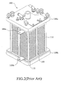
- a plurality of such single cells are stacked to configure a fuel cell stack as shown in Fig. 2 .
- the complete fuel cell stack is able to perform the desired conductive reactions under a predetermined compression pressure by fastening a plurality of tie rods 110 therethrough.
- the primary objective of this invention is to provide a single cell of a fuel cell, particularly a single cell of a PEMFC or a module thereof assembled by the single cells, by means of modulizing and unitizing the cell and module, to simplify the manufacturing process of a PEMFC. Because it is possible to test the performance of each single cell or module in advance according to this invention, the quality of the whole fuel cell is significantly improved and the manufacturing cost thereof is reduced to a mass production scale, thereby practically replacing the existing energy.
- Another objective of this invention is to provide a sealing structure for a fuel cell assembled by a plurality of modulized single cells or modules.
- Yet a further object of this invention is to provide a single cell of a fuel cell or a module comprising the single cells with excellent gastight effect.
- a sealing structure for sealing a proton exchange membrane fuel cell.
- the fuel cell includes a membrane electrode assembly, an anode plate, and a cathode plate. Both of the plates are formed with a peripheral groove and an extended groove at a circumferential portion thereof, and silicon rubber is applied to the peripheral groove and the extended groove.
- the anode plate, the membrane electrode assembly and the cathode plate are stacked and compressed with a predetermined compression pressure, such that the silicon rubber at the peripheral groove of the anode plate binds correspondingly to the silicon rubber at the peripheral groove of the cathode plate to form a tight sealing at the circumferential portions between the anode plate and the cathode plate, and the membrane electrode assembly is tightly sandwiched between the silicon rubber at the extended groove of the anode plate and the silicon rubber at the extended groove of the cathode plate to form a tight sealing around the ports between the anode plate and cathode plate.
- Fig. 1 is a schematic view showing a cross-section of the single cell of a prior art fuel cell
- Fig. 2 is a perspective view of an assembled prior art fuel cell stack
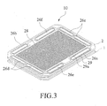
- Fig. 3 is a schematic view showing a cross-section of a modulized single cell of a fuel cell according to the present invention
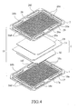
- Fig. 4 is an exploded view showing the components of the single cell of Fig. 3 ;
- Figs. 5A to 5D are cross-sectional views showing the assembly of the single cell according to a first embodiment of the present invention.
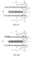
- Figs. 6A to 6B are cross-sectional views showing the stacking of two single cells of Fig. 5D to form a fuel cell module in accordance with a second embodiment of the present invention
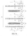
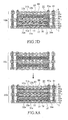
- Figs. 7A to 7D are cross-sectional views showing the assembly of the cell module according to a third embodiment of the present invention.
- Figs. 8A to 8B are cross-sectional views showing the stacking of two cell modules of Fig. 7D to form a fuel cell stack in accordance with a fourth embodiment of the present invention.
- Fig. 3 shows a modulized single cell 10 of a Proton Exchange Membrane Fuel Cell (PEMFC) according to the present invention.
- Fig. 4 is an exploded view showing the components of the modulized single cell 10 and
- Fig. 5A is a cross-sectional view of the components.
- PEMFC Proton Exchange Membrane Fuel Cell
- the modulized single cell 10 includes an anode plate 1 and a cathode plate 2, serving as separator plates for the fuel cell.
- the anode plate 1 has a first surface 11, a second surface 12, a central portion 13 and a circumferential portion 14.
- the central portion 13 on the first surface 11 is formed with a plurality of anode gas channels 15 having predetermined layout for hydrogen flowing therethrough.
- the circumferential portion 14 of the anode plate 1 is formed with a hydrogen inlet port 16a, a hydrogen outlet port 16b, an air inlet port 16c, an air outlet port 16d, a coolant inlet port 16e and a coolant outlet port 16f.
- the second surface 12 of the anode plate 1 is generally flat in structure.
- the cathode plate 2 has a first surface 21, a second surface 22, a central portion 23 and a circumferential portion 24.
- the central portion 23 on the second surface 22 is formed with a plurality of cathode gas channels 25 having predetermined layout for air flowing therethrough.
- the circumferential portion 24 of the cathode plate 2 is formed with a hydrogen inlet port 26a, a hydrogen outlet port 26b, an air inlet port 26c, an air outlet port 26d, a coolant inlet port 26e, and a coolant outlet port 26f.
- the hydrogen inlet port 26a, the hydrogen outlet port 26b, the air inlet port 26c, the air outlet port 26d, the coolant inlet port 26e, and the coolant outlet port 26f at the circumferential portion 24 of the cathode plate 2 are located oppositely and communicated respectively with the hydrogen inlet port 16a, the hydrogen outlet port 16b, the air inlet port 16c, the air outlet port 16d, the coolant inlet port 16e and the coolant outlet port 16f at the circumferential portion 14 of the anode plate 1, forming passages for flowing of hydrogen, air, and coolant respectively.
- a membrane electrode assembly (MEA) 3 is mounted between the anode plate 1 and cathode plate 2.
- the MEA 3 has an anode gas diffusion layer (GDL) 32, a proton exchange membrane (PEM) 31 and a cathode gas diffusion layer (GDL) 33, that are sequentially stacked and lo.cated between the central portion 13 of the anode plate 1 and the central portion 23 of the cathode plate 2.
- GDL anode gas diffusion layer
- PEM proton exchange membrane
- GDL cathode gas diffusion layer
- An anode catalytic layer (not shown) is coated between the anode GDL 32 and the PEM 31, and a cathode catalytic layer (not shown) is coated between the PEM 31 and the cathode GDL 33, such that the hydrogen introduced through the channels 15 of the anode plate 1 and the oxygen introduced through the channels 25 of the cathode plate 2 are adapted to proceed with the reverse reaction of the electrolytic dissociation of water.
- the first surface 11 of the circumferential portion 14 of the anode plate 1 is formed with a peripheral groove 17. Also, an extended groove 17a is formed in the vicinity of the ports 16a, 16b, 16c, 16d, 16e, 16f and communicated with the peripheral groove 17.
- the second surface 22 of the circumferential portion 24 of the cathode plate 2 facing the anode plate 1 is formed with a peripheral groove 27.
- An extended groove 27a is formed in the vicinity the ports 26a, 26b, 26c, 26d, 26e, 26f and communicated with the peripheral groove 27.
- the first surface 21 of the central portion 23 of the cathode plate 2 is also formed with a plurality of coolant channels 28 having predetermined layout for coolant flowing therethrough.
- the first surface 21 at the circumferential portion 24 of the cathode plate 2 is formed with a peripheral groove 29.
- An extended groove 29a is formed in the vicinity of the ports 26a, 26b, 26c, 26d, 26e, 26f and communicated with the peripheral groove 29.
- the silicon rubber 5 at the peripheral groove 17 of the anode plate 1 binds to the silicon rubber 6 at the peripheral groove 27 of the cathode plate 2, forming a tight sealing at the circumferential portion 14 between the anode plate 1 and cathode plate 2.
- the PEM 31 of the MEA 3 is adhered by the silicon rubber 5a at the extended groove 17a of the anode plate 1 and the silicon rubber 6a at the extended groove 27a of the cathode plate 2.
- the PEM 31 is stably located in position between the anode plate 1 and the cathode plate 2, and tight sealing are formed around the ports between the anode plate 1 and cathode plate 2 after the silicon rubbers are cured.
- each of the ports 16a, 16b, 16c, 16d, 16e, 16f at the anode plate 1 is only in communication respectively with the corresponding ports 26a, 26b, 26c, 26d, 26e, 26f at the cathode plate 2. Accordingly, a modulized unitary single cell 10 is formed.
- the single cell 10 is tightly sealed at the circumferential portion.
- the anode plate, MEA and cathode plate are stably positioned and fastened to each other. Sealing is provided between the ports of the anode plate and cathode plate, forming a plurality of separate passages. Thereby, hydrogen gas, oxygen gas and coolant are separately transported and sealed from leakage.
- silicon rubber is used as the adhesive material for binding the separator plates of the single cell 10.
- the silicon rubber is selected from material which has non-corrosive electronic grade and can be cured under moisture or heat.
- the silicon rubber made of heat-cured material in the event that the silicon rubber made of heat-cured material is utilized for the manufacture of the single cell, the silicon rubber generally has a heat-cured temperature of 100-140°C. Because the curing temperature of the silicon rubber is higher than the working temperature (lower than 100°C) of PEMFC, the silicon rubber is stable and can perform an optimal after-cured effect thereof. Preferably, to provide an optimal sealing and positioning effect, the viscosity of the silicon rubber utilized is greater than 150,000 centi-poise. Furthermore, the silicon rubber having a dielectric strength ranging from 15-20 V/mil would sufficiently perform a considerable electricity resistance. Nevertheless, the above-mentioned values are proposed for people skilled in this field to implement the present invention under a preferred situation. It dos not mean that any values going beyond the proposed ranges cannot perform well the expected functions as set forth therein.
- Fig. 6a shows a cross-sectional view of a second embodiment of the present invention, in which two single cells are superimposed to form a fuel cell module.
- Two modulized single cells 10, 10a are formed in accordance with the technology as mentioned. Please refer to Fig. 6B .
- the single cells 10, 10a are then stacked together, such that the anode plate 1 at the bottom of the second single cell 10a is superimposed on the top of the cathode plate 2 of the first single cell 10.
- the plane structure of the second surface of the anode plate of the second single cell 10a forms the top surface of the coolant channels on the first surface 21 of the cathode plate 2, providing a passage for coolant flowing therethrough.
- the silicon rubbers 4, 4a which are previously applied at the first surface 21 of the cathode plate 2 of the first single cell 10 and by compressing the two modulized single cells 10, 10a with a predetermined compression pressure, the two single cells 10, 10a are stably bound together and the coolant channels 28 are tightly sealed.
- Fig. 7A is a cross-sectional view showing the cell module constructed in accordance with a third embodiment of the present invention.
- the cell module comprises two MEAs, one bipolar plate, an anode plate and a cathode plate. Similar reference numerals are used to identify elements that are similar or identical as that in Figs. 5A to 5D .
- the cell module 10b comprises an anode plate 1, a bipolar plate 7 and a first MEA 3a.
- the anode plate 1 has a first surface 11, a second surface 12, a central portion 13, a circumferential portion 14, a plurality of anode gas channels 15, a peripheral groove 17, an extended groove 17a, and a plurality of ports.
- the bipolar plate 7 comprises a first surface 71, a second surface 72, a central portion 73, a peripheral portion 74, a plurality of cathode gas channels 75, a peripheral groove 77, an extended groove 77a, a peripheral groove 79, an extended groove 79a, and a plurality of ports.
- the first surface 71 of the central portion 73 is formed with a plurality of anode gas channels 78 for anode gas flowing therethrough.
- the first MEA 3a comprises a proton exchange membrane 31a, an anode gas diffusion layer 32a and a cathode gas diffusion layer 33a.
- a second MEA 3b is stacked on the first surface 71 of the bipolar plate 7.
- the second MEA 3b comprises a proton exchange membrane 31b, an anode gas diffusion layer 32b and a cathode gas diffusion layer 33b, in which the anode gas diffusion layer 32b of the second MEA 3b is superimposed on the central portion 73 at the first surface 71 of the bipolar plate 7.
- a cathode plate 8 is then stacked on the top of the anode gas diffusion layer 33b of the second MEA 3b.
- the cathode plate 8 includes a first surface 81, a second surface 82, a central portion 83, a circumferential portion 84, a plurality of cathode gas channels 85, a peripheral groove 87 and an extended groove 87a formed at the second surface 82, a peripheral groove 89 and an extended groove 89a formed at the first surface 81 and a plurality of ports. Also, a plurality of coolant channels 88 are formed at the first surface 81 of the central portion 83 of the cathode plate 8 for coolant flowing therethrough.
- the peripheral groove 89 and extended groove 89a at the first surface 81 of the circumferential portion 84 are dispensed with silicon rubbers 91, 91a, as shown in Fig. 7B .
- the silicon rubbers 91, 91a are cured.
- the peripheral groove 17 and extended groove 17a of the anode plate 1 are applied with silicon rubbers 92, 92a.
- the peripheral grooves 77, 79 and extended grooves 77a, 79a of the bipolar plate 7 and the peripheral groove 87 and extended groove 87a of the cathode plate 8 are respectively applied with silicon rubbers 93, 94, 93a, 94a, 95, 95a.
- the anode plate 1, first MEA 3a, bipolar plate 7, second MEA 3b, and cathode plate 8 are precisely stacked in proper order and compressed with a predetermined compression pressure, as shown in Fig. 7D .
- the silicon rubbers 92, 93, 94, 95 on each plate stick to the corresponding silicon rubbers at the opposing surface and is cured to form a tight sealing.
- the sealing tightly seal the circumferential portions among the anode plate 1, bipolar plate 7 and cathode plate 8.
- the silicon rubbers 92a, 93a correspondingly stick to the proton exchange membrane 31a of the first MEA 3a and the silicon rubbers 94a, 95a correspondingly stick to the proton exchange membrane 31b of the second MEA 3b, such that the first and second MEA 3a, 3b are stably anchored in position and sealings are formed around the ports between adjacent plates.
- an integrated modularized cell module 10b is formed.
- Figs. 8A to 8B are cross-sectional views showing the stacking of two cell modules of Fig. 7D to form a fuel cell stack in accordance with a fourth embodiment of the present invention.
- two cell modules 10b, 10c manufactured by the technology are stacked together in series, such that the second surface of the anode plate of the cell module 10c is superimposed on the first surface of the cathode plate of cell module 10b, as shown in Fig. 8b .
- the flat structure of the second surface of the anode plate of cell module 10c forms the top surface of the coolant channels on the first surface of the cathode plate 8.
- the silicon rubbers 91, 91a applied at the first surface of the cathode plate 8 of the cell module 10b, and by compressing the two cell modules 10b, 10c with a predetermined compression pressure, the two cell modules are bound together, forming a tight structure. Hence, the coolant channels are tightly sealed for flowing of coolant therethrough.
Landscapes
- Life Sciences & Earth Sciences (AREA)
- Engineering & Computer Science (AREA)
- Manufacturing & Machinery (AREA)
- Sustainable Development (AREA)
- Sustainable Energy (AREA)
- Chemical & Material Sciences (AREA)
- Chemical Kinetics & Catalysis (AREA)
- Electrochemistry (AREA)
- General Chemical & Material Sciences (AREA)
- Fuel Cell (AREA)
Applications Claiming Priority (2)
| Application Number | Priority Date | Filing Date | Title |
|---|---|---|---|
| CNB2003101215962A CN100438132C (zh) | 2003-12-29 | 2003-12-29 | 模块化质子交换膜燃料电池的密封结构 |
| EP04016256.2A EP1553652B1 (fr) | 2003-12-29 | 2004-07-09 | Structure d'étanchéité pour rendre étanche des plaques de séparateur de modules de piles à combustible |
Related Parent Applications (2)
| Application Number | Title | Priority Date | Filing Date |
|---|---|---|---|
| EP04016256.2 Division | 2004-07-09 | ||
| EP04016256.2A Division-Into EP1553652B1 (fr) | 2003-12-29 | 2004-07-09 | Structure d'étanchéité pour rendre étanche des plaques de séparateur de modules de piles à combustible |
Publications (2)
| Publication Number | Publication Date |
|---|---|
| EP2273593A2 true EP2273593A2 (fr) | 2011-01-12 |
| EP2273593A3 EP2273593A3 (fr) | 2011-09-21 |
Family
ID=34580584
Family Applications (2)
| Application Number | Title | Priority Date | Filing Date |
|---|---|---|---|
| EP04016256.2A Expired - Lifetime EP1553652B1 (fr) | 2003-12-29 | 2004-07-09 | Structure d'étanchéité pour rendre étanche des plaques de séparateur de modules de piles à combustible |
| EP10012866A Withdrawn EP2273593A3 (fr) | 2003-12-29 | 2004-07-09 | Structure d'étanchéité pour rendre étanche des plaques de séparateur de modules de piles à combustible |
Family Applications Before (1)
| Application Number | Title | Priority Date | Filing Date |
|---|---|---|---|
| EP04016256.2A Expired - Lifetime EP1553652B1 (fr) | 2003-12-29 | 2004-07-09 | Structure d'étanchéité pour rendre étanche des plaques de séparateur de modules de piles à combustible |
Country Status (2)
| Country | Link |
|---|---|
| EP (2) | EP1553652B1 (fr) |
| CN (1) | CN100438132C (fr) |
Cited By (1)
| Publication number | Priority date | Publication date | Assignee | Title |
|---|---|---|---|---|
| EP4628629A3 (fr) * | 2024-04-01 | 2026-03-11 | Robert Bosch GmbH | Unité électrolytique et empilement électrolytique |
Families Citing this family (22)
| Publication number | Priority date | Publication date | Assignee | Title |
|---|---|---|---|---|
| JP5087863B2 (ja) * | 2006-06-09 | 2012-12-05 | トヨタ自動車株式会社 | 燃料電池 |
| DE102006032530A1 (de) * | 2006-07-12 | 2008-01-17 | Carl Freudenberg Kg | Modul für eine Brennstoffzellenanordnung |
| KR100785115B1 (ko) | 2006-11-22 | 2007-12-11 | 현대자동차주식회사 | 연료전지 차량의 분리판 결합 구조 |
| CN100570942C (zh) * | 2007-03-28 | 2009-12-16 | 南亚电路板股份有限公司 | 燃料电池模块结构 |
| US8211585B2 (en) * | 2008-04-08 | 2012-07-03 | GM Global Technology Operations LLC | Seal for PEM fuel cell plate |
| US8911918B2 (en) | 2010-02-08 | 2014-12-16 | GM Global Technology Operations LLC | Hybrid seal application process |
| GB2502517A (en) * | 2012-05-28 | 2013-12-04 | Intelligent Energy Ltd | Fuel Cell Plate Assemblies and methods of assembly thereof |
| JP6024398B2 (ja) * | 2012-11-06 | 2016-11-16 | 大日本印刷株式会社 | 補強材付き触媒層−電解質膜積層体、固体高分子形燃料電池、及び、補強材付き触媒層−電解質膜積層体の製造方法 |
| CN102938468A (zh) * | 2012-12-03 | 2013-02-20 | 新源动力股份有限公司 | 一种燃料电池强化密封方法 |
| DE102016202481A1 (de) | 2016-02-18 | 2017-08-24 | Volkswagen Aktiengesellschaft | Brennstoffzellenstapel und Verfahren zum Herstellen eines solchen Brennstoffzellenstapels |
| CN105776446A (zh) * | 2016-05-23 | 2016-07-20 | 汪万法 | 无槽体电解装置 |
| CN108767290A (zh) * | 2018-05-28 | 2018-11-06 | 上海治臻新能源装备有限公司 | 一种用于燃料电池装配的自定位组装结构 |
| CN109509894B (zh) * | 2018-12-05 | 2024-03-12 | 国家电投集团氢能科技发展有限公司 | 单体燃料电池和燃料电池电堆 |
| CN109524685B (zh) * | 2018-12-05 | 2024-03-12 | 国家电投集团氢能科技发展有限公司 | 单体燃料电池和燃料电池电堆 |
| CN109509892B (zh) * | 2018-12-05 | 2024-02-23 | 国家电投集团氢能科技发展有限公司 | 燃料电池分隔件、单体燃料电池和燃料电池电堆 |
| CN109980245B (zh) * | 2019-03-22 | 2021-10-29 | 苏州钧峰新能源科技有限公司 | 一种直接甲醇燃料电池中双极板与膜电极的密封方法 |
| CN110400944A (zh) * | 2019-06-28 | 2019-11-01 | 上海电气集团股份有限公司 | 一种燃料电池膜电极与边框的密封方法与密封结构 |
| CN110828844A (zh) * | 2019-11-11 | 2020-02-21 | 上海骥翀氢能科技有限公司 | 一种高性能质子交换膜燃料电池阴阳极流场及其双极板 |
| CN111106361B (zh) * | 2019-12-23 | 2021-03-30 | 清华大学 | 燃料电池堆、双极板及气体扩散层 |
| DE102023208234A1 (de) * | 2023-08-29 | 2025-03-06 | Cellcentric Gmbh & Co. Kg | Bipolarplatte für eine brennstoffzelle |
| CN118996457B (zh) * | 2024-10-24 | 2025-04-29 | 爱德曼氢能源装备有限公司 | 一种密封式pem电解槽单电池结构及含有其的pem电解槽 |
| CN119433557A (zh) * | 2025-01-07 | 2025-02-14 | 上海氢盛创合能源科技有限公司 | Pem电解槽制氢单元及其制作方法 |
Family Cites Families (5)
| Publication number | Priority date | Publication date | Assignee | Title |
|---|---|---|---|---|
| JP2001118592A (ja) * | 1999-10-18 | 2001-04-27 | Matsushita Electric Ind Co Ltd | 高分子電解質型燃料電池及び電池スタック |
| CA2345852C (fr) * | 2000-05-02 | 2008-11-18 | Honda Giken Kogyo Kabushiki Kaisha | Pile a combustible avec compose pour etancheifier une membrane d'electrolyte polymere solide |
| JP4923319B2 (ja) | 2000-07-25 | 2012-04-25 | トヨタ自動車株式会社 | 燃料電池 |
| JP4043724B2 (ja) * | 2001-02-14 | 2008-02-06 | 本田技研工業株式会社 | 単位燃料電池及び燃料電池スタックの製造方法 |
| US6852439B2 (en) * | 2001-05-15 | 2005-02-08 | Hydrogenics Corporation | Apparatus for and method of forming seals in fuel cells and fuel cell stacks |
-
2003
- 2003-12-29 CN CNB2003101215962A patent/CN100438132C/zh not_active Expired - Lifetime
-
2004
- 2004-07-09 EP EP04016256.2A patent/EP1553652B1/fr not_active Expired - Lifetime
- 2004-07-09 EP EP10012866A patent/EP2273593A3/fr not_active Withdrawn
Non-Patent Citations (1)
| Title |
|---|
| None |
Cited By (1)
| Publication number | Priority date | Publication date | Assignee | Title |
|---|---|---|---|---|
| EP4628629A3 (fr) * | 2024-04-01 | 2026-03-11 | Robert Bosch GmbH | Unité électrolytique et empilement électrolytique |
Also Published As
| Publication number | Publication date |
|---|---|
| CN100438132C (zh) | 2008-11-26 |
| CN1635643A (zh) | 2005-07-06 |
| EP2273593A3 (fr) | 2011-09-21 |
| EP1553652B1 (fr) | 2014-06-04 |
| EP1553652A3 (fr) | 2007-04-18 |
| EP1553652A2 (fr) | 2005-07-13 |
Similar Documents
| Publication | Publication Date | Title |
|---|---|---|
| CA2473870C (fr) | Structures de scellement pour sceller des plaques de separation de modules de pile a combustible | |
| EP1553652B1 (fr) | Structure d'étanchéité pour rendre étanche des plaques de séparateur de modules de piles à combustible | |
| US7070876B2 (en) | Membrane electrode assembly with integrated seal | |
| US7014940B2 (en) | High-polymer electrolyte fuel cell | |
| US8551671B2 (en) | Fuel cell fluid sealing structure | |
| US7405019B2 (en) | Polymer electrolyte fuel cell | |
| KR100413891B1 (ko) | 연료전지 | |
| EP1286408A2 (fr) | Pile à combustible modulaire et assemblage de piles à combustible à électrolyte polymèrique solide | |
| US20110281193A1 (en) | Fuel cell fluid distribution system | |
| CN111244496B (zh) | 燃料电池及配流装置 | |
| JP2005502995A (ja) | モジュール式燃料電池カートリッジおよびスタック | |
| US20020110720A1 (en) | Modulized single cell and assembled cell unit of a proton exchange membrane fuel cell | |
| US20100297533A1 (en) | Fuel cell and method of manufacturing same | |
| CN107994239B (zh) | 在压条和流道之间的交叉处的金属压条密封上具有更具弹性的接触压力分布的流道截面设计 | |
| US20090291344A1 (en) | Fuel cell | |
| EP2012383A1 (fr) | Element de mea et pile a combustible a polyelectrolytes | |
| US7824817B2 (en) | Fuel cell | |
| US20110008703A1 (en) | Fuel cell with dead-end anode | |
| US20080076005A1 (en) | Fuel cell fluid distribution system | |
| KR100808028B1 (ko) | 단전지들이 평면 배열된 등가의 대면적 연료전지 및 이에사용되는 압축형 밀봉재 | |
| KR102875398B1 (ko) | 연료전지 장치 | |
| KR102927067B1 (ko) | 연료전지 장치 | |
| KR102899513B1 (ko) | 연료전지 장치 | |
| EP4557413A1 (fr) | Ensemble d'extrémité d'un empilement de piles à combustible et empilement de piles à combustible | |
| CN211929634U (zh) | 用于燃料电池的接口板 |
Legal Events
| Date | Code | Title | Description |
|---|---|---|---|
| PUAI | Public reference made under article 153(3) epc to a published international application that has entered the european phase |
Free format text: ORIGINAL CODE: 0009012 |
|
| AC | Divisional application: reference to earlier application |
Ref document number: 1553652 Country of ref document: EP Kind code of ref document: P |
|
| AK | Designated contracting states |
Kind code of ref document: A2 Designated state(s): AT BE BG CH CY CZ DE DK EE ES FI FR GB GR HU IE IT LI LU MC NL PL PT RO SE SI SK TR |
|
| PUAL | Search report despatched |
Free format text: ORIGINAL CODE: 0009013 |
|
| AK | Designated contracting states |
Kind code of ref document: A3 Designated state(s): AT BE BG CH CY CZ DE DK EE ES FI FR GB GR HU IE IT LI LU MC NL PL PT RO SE SI SK TR |
|
| RIC1 | Information provided on ipc code assigned before grant |
Ipc: H01M 8/24 20060101ALI20110812BHEP Ipc: H01M 8/02 20060101AFI20110812BHEP |
|
| STAA | Information on the status of an ep patent application or granted ep patent |
Free format text: STATUS: THE APPLICATION IS DEEMED TO BE WITHDRAWN |
|
| 18D | Application deemed to be withdrawn |
Effective date: 20120322 |