EP2273595A1 - Festoxidbrennstoffzelle - Google Patents
Festoxidbrennstoffzelle Download PDFInfo
- Publication number
- EP2273595A1 EP2273595A1 EP10251110A EP10251110A EP2273595A1 EP 2273595 A1 EP2273595 A1 EP 2273595A1 EP 10251110 A EP10251110 A EP 10251110A EP 10251110 A EP10251110 A EP 10251110A EP 2273595 A1 EP2273595 A1 EP 2273595A1
- Authority
- EP
- European Patent Office
- Prior art keywords
- electrode layer
- fuel
- fuel electrode
- stacked body
- layer
- Prior art date
- Legal status (The legal status is an assumption and is not a legal conclusion. Google has not performed a legal analysis and makes no representation as to the accuracy of the status listed.)
- Granted
Links
- 239000000446 fuel Substances 0.000 title claims abstract description 278
- 239000007787 solid Substances 0.000 title claims abstract description 21
- 229910052845 zircon Inorganic materials 0.000 claims abstract description 94
- GFQYVLUOOAAOGM-UHFFFAOYSA-N zirconium(iv) silicate Chemical compound [Zr+4].[O-][Si]([O-])([O-])[O-] GFQYVLUOOAAOGM-UHFFFAOYSA-N 0.000 claims abstract description 85
- 239000003792 electrolyte Substances 0.000 claims abstract description 56
- 239000002245 particle Substances 0.000 claims description 68
- 239000000463 material Substances 0.000 claims description 38
- 239000007789 gas Substances 0.000 claims description 29
- 239000002737 fuel gas Substances 0.000 claims description 23
- 239000001301 oxygen Substances 0.000 claims description 20
- 229910052760 oxygen Inorganic materials 0.000 claims description 20
- QVGXLLKOCUKJST-UHFFFAOYSA-N atomic oxygen Chemical compound [O] QVGXLLKOCUKJST-UHFFFAOYSA-N 0.000 claims description 17
- 239000004020 conductor Substances 0.000 claims description 4
- 239000007784 solid electrolyte Substances 0.000 claims description 4
- -1 oxygen ion Chemical class 0.000 claims description 3
- 230000008602 contraction Effects 0.000 abstract description 29
- 238000011946 reduction process Methods 0.000 abstract description 26
- 230000009467 reduction Effects 0.000 description 37
- 229910001233 yttria-stabilized zirconia Inorganic materials 0.000 description 32
- 239000000843 powder Substances 0.000 description 28
- 239000010408 film Substances 0.000 description 27
- PXHVJJICTQNCMI-UHFFFAOYSA-N Nickel Chemical compound [Ni] PXHVJJICTQNCMI-UHFFFAOYSA-N 0.000 description 26
- 238000006243 chemical reaction Methods 0.000 description 19
- 238000000034 method Methods 0.000 description 15
- 239000011195 cermet Substances 0.000 description 10
- 239000000853 adhesive Substances 0.000 description 9
- 230000008878 coupling Effects 0.000 description 9
- 238000010168 coupling process Methods 0.000 description 9
- 238000005859 coupling reaction Methods 0.000 description 9
- 230000008569 process Effects 0.000 description 8
- MCMNRKCIXSYSNV-UHFFFAOYSA-N Zirconium dioxide Chemical compound O=[Zr]=O MCMNRKCIXSYSNV-UHFFFAOYSA-N 0.000 description 7
- 239000000919 ceramic Substances 0.000 description 7
- RUDFQVOCFDJEEF-UHFFFAOYSA-N yttrium(III) oxide Inorganic materials [O-2].[O-2].[O-2].[Y+3].[Y+3] RUDFQVOCFDJEEF-UHFFFAOYSA-N 0.000 description 7
- 229910000859 α-Fe Inorganic materials 0.000 description 7
- 230000000694 effects Effects 0.000 description 6
- 230000000052 comparative effect Effects 0.000 description 5
- 238000002474 experimental method Methods 0.000 description 5
- 229910052746 lanthanum Inorganic materials 0.000 description 5
- FZLIPJUXYLNCLC-UHFFFAOYSA-N lanthanum atom Chemical compound [La] FZLIPJUXYLNCLC-UHFFFAOYSA-N 0.000 description 5
- 229910052751 metal Inorganic materials 0.000 description 5
- 239000002184 metal Substances 0.000 description 5
- UFHFLCQGNIYNRP-UHFFFAOYSA-N Hydrogen Chemical compound [H][H] UFHFLCQGNIYNRP-UHFFFAOYSA-N 0.000 description 4
- 239000003795 chemical substances by application Substances 0.000 description 4
- 230000003247 decreasing effect Effects 0.000 description 4
- 238000010438 heat treatment Methods 0.000 description 4
- 238000004519 manufacturing process Methods 0.000 description 4
- BASFCYQUMIYNBI-UHFFFAOYSA-N platinum Chemical compound [Pt] BASFCYQUMIYNBI-UHFFFAOYSA-N 0.000 description 4
- 238000007639 printing Methods 0.000 description 4
- 239000002002 slurry Substances 0.000 description 4
- 230000037237 body shape Effects 0.000 description 3
- 238000009826 distribution Methods 0.000 description 3
- 230000005611 electricity Effects 0.000 description 3
- 239000011810 insulating material Substances 0.000 description 3
- 230000007246 mechanism Effects 0.000 description 3
- 150000002739 metals Chemical class 0.000 description 3
- XEEYBQQBJWHFJM-UHFFFAOYSA-N Iron Chemical compound [Fe] XEEYBQQBJWHFJM-UHFFFAOYSA-N 0.000 description 2
- KDLHZDBZIXYQEI-UHFFFAOYSA-N Palladium Chemical compound [Pd] KDLHZDBZIXYQEI-UHFFFAOYSA-N 0.000 description 2
- KJTLSVCANCCWHF-UHFFFAOYSA-N Ruthenium Chemical compound [Ru] KJTLSVCANCCWHF-UHFFFAOYSA-N 0.000 description 2
- QBYHSJRFOXINMH-UHFFFAOYSA-N [Co].[Sr].[La] Chemical compound [Co].[Sr].[La] QBYHSJRFOXINMH-UHFFFAOYSA-N 0.000 description 2
- BQENXCOZCUHKRE-UHFFFAOYSA-N [La+3].[La+3].[O-][Mn]([O-])=O.[O-][Mn]([O-])=O.[O-][Mn]([O-])=O Chemical compound [La+3].[La+3].[O-][Mn]([O-])=O.[O-][Mn]([O-])=O.[O-][Mn]([O-])=O BQENXCOZCUHKRE-UHFFFAOYSA-N 0.000 description 2
- GMPSWULASZPKFN-UHFFFAOYSA-N [O-2].[Ce+3].[Pt+2] Chemical compound [O-2].[Ce+3].[Pt+2] GMPSWULASZPKFN-UHFFFAOYSA-N 0.000 description 2
- 230000004075 alteration Effects 0.000 description 2
- 230000015572 biosynthetic process Effects 0.000 description 2
- 229920002678 cellulose Polymers 0.000 description 2
- 239000001913 cellulose Substances 0.000 description 2
- CETPSERCERDGAM-UHFFFAOYSA-N ceric oxide Chemical compound O=[Ce]=O CETPSERCERDGAM-UHFFFAOYSA-N 0.000 description 2
- 229910000422 cerium(IV) oxide Inorganic materials 0.000 description 2
- 229910052963 cobaltite Inorganic materials 0.000 description 2
- 238000011156 evaluation Methods 0.000 description 2
- 239000010419 fine particle Substances 0.000 description 2
- 238000010304 firing Methods 0.000 description 2
- 239000011521 glass Substances 0.000 description 2
- 239000001257 hydrogen Substances 0.000 description 2
- 229910052739 hydrogen Inorganic materials 0.000 description 2
- 229910052759 nickel Inorganic materials 0.000 description 2
- GNRSAWUEBMWBQH-UHFFFAOYSA-N nickel(II) oxide Inorganic materials [Ni]=O GNRSAWUEBMWBQH-UHFFFAOYSA-N 0.000 description 2
- 229910052697 platinum Inorganic materials 0.000 description 2
- 231100000572 poisoning Toxicity 0.000 description 2
- 230000000607 poisoning effect Effects 0.000 description 2
- 238000003825 pressing Methods 0.000 description 2
- 229910052707 ruthenium Inorganic materials 0.000 description 2
- 238000005245 sintering Methods 0.000 description 2
- 230000001629 suppression Effects 0.000 description 2
- OYPRJOBELJOOCE-UHFFFAOYSA-N Calcium Chemical compound [Ca] OYPRJOBELJOOCE-UHFFFAOYSA-N 0.000 description 1
- VYZAMTAEIAYCRO-UHFFFAOYSA-N Chromium Chemical compound [Cr] VYZAMTAEIAYCRO-UHFFFAOYSA-N 0.000 description 1
- 230000002159 abnormal effect Effects 0.000 description 1
- 239000000654 additive Substances 0.000 description 1
- 230000000996 additive effect Effects 0.000 description 1
- 229910052782 aluminium Inorganic materials 0.000 description 1
- XAGFODPZIPBFFR-UHFFFAOYSA-N aluminium Chemical compound [Al] XAGFODPZIPBFFR-UHFFFAOYSA-N 0.000 description 1
- 238000004458 analytical method Methods 0.000 description 1
- 239000011575 calcium Substances 0.000 description 1
- 229910052791 calcium Inorganic materials 0.000 description 1
- 229910000420 cerium oxide Inorganic materials 0.000 description 1
- WEDXVUHOBZDVHR-UHFFFAOYSA-N cerium(3+) oxygen(2-) ruthenium(3+) Chemical compound [O-2].[Ce+3].[Ru+3].[O-2].[O-2] WEDXVUHOBZDVHR-UHFFFAOYSA-N 0.000 description 1
- 229910052804 chromium Inorganic materials 0.000 description 1
- 239000011651 chromium Substances 0.000 description 1
- NFYLSJDPENHSBT-UHFFFAOYSA-N chromium(3+);lanthanum(3+);oxygen(2-) Chemical compound [O-2].[O-2].[O-2].[Cr+3].[La+3] NFYLSJDPENHSBT-UHFFFAOYSA-N 0.000 description 1
- 229910017052 cobalt Inorganic materials 0.000 description 1
- 239000010941 cobalt Substances 0.000 description 1
- GUTLYIVDDKVIGB-UHFFFAOYSA-N cobalt atom Chemical compound [Co] GUTLYIVDDKVIGB-UHFFFAOYSA-N 0.000 description 1
- 238000002485 combustion reaction Methods 0.000 description 1
- 238000005520 cutting process Methods 0.000 description 1
- 238000005530 etching Methods 0.000 description 1
- 229910052742 iron Inorganic materials 0.000 description 1
- 238000002156 mixing Methods 0.000 description 1
- 238000000465 moulding Methods 0.000 description 1
- 230000001151 other effect Effects 0.000 description 1
- 229910052763 palladium Inorganic materials 0.000 description 1
- 238000003672 processing method Methods 0.000 description 1
- 239000002994 raw material Substances 0.000 description 1
- 230000002787 reinforcement Effects 0.000 description 1
- 238000007789 sealing Methods 0.000 description 1
- 229910052712 strontium Inorganic materials 0.000 description 1
- CIOAGBVUUVVLOB-UHFFFAOYSA-N strontium atom Chemical compound [Sr] CIOAGBVUUVVLOB-UHFFFAOYSA-N 0.000 description 1
- 239000000758 substrate Substances 0.000 description 1
- 230000008646 thermal stress Effects 0.000 description 1
- 239000010409 thin film Substances 0.000 description 1
Images










Classifications
-
- H—ELECTRICITY
- H01—ELECTRIC ELEMENTS
- H01M—PROCESSES OR MEANS, e.g. BATTERIES, FOR THE DIRECT CONVERSION OF CHEMICAL ENERGY INTO ELECTRICAL ENERGY
- H01M4/00—Electrodes
- H01M4/86—Inert electrodes with catalytic activity, e.g. for fuel cells
- H01M4/90—Selection of catalytic material
- H01M4/9041—Metals or alloys
- H01M4/905—Metals or alloys specially used in fuel cell operating at high temperature, e.g. SOFC
- H01M4/9066—Metals or alloys specially used in fuel cell operating at high temperature, e.g. SOFC of metal-ceramic composites or mixtures, e.g. cermets
-
- H—ELECTRICITY
- H01—ELECTRIC ELEMENTS
- H01M—PROCESSES OR MEANS, e.g. BATTERIES, FOR THE DIRECT CONVERSION OF CHEMICAL ENERGY INTO ELECTRICAL ENERGY
- H01M4/00—Electrodes
- H01M4/86—Inert electrodes with catalytic activity, e.g. for fuel cells
- H01M4/8647—Inert electrodes with catalytic activity, e.g. for fuel cells consisting of more than one material, e.g. consisting of composites
- H01M4/8657—Inert electrodes with catalytic activity, e.g. for fuel cells consisting of more than one material, e.g. consisting of composites layered
-
- H—ELECTRICITY
- H01—ELECTRIC ELEMENTS
- H01M—PROCESSES OR MEANS, e.g. BATTERIES, FOR THE DIRECT CONVERSION OF CHEMICAL ENERGY INTO ELECTRICAL ENERGY
- H01M8/00—Fuel cells; Manufacture thereof
- H01M8/24—Grouping of fuel cells, e.g. stacking of fuel cells
- H01M8/241—Grouping of fuel cells, e.g. stacking of fuel cells with solid or matrix-supported electrolytes
- H01M8/2425—High-temperature cells with solid electrolytes
- H01M8/2432—Grouping of unit cells of planar configuration
-
- H—ELECTRICITY
- H01—ELECTRIC ELEMENTS
- H01M—PROCESSES OR MEANS, e.g. BATTERIES, FOR THE DIRECT CONVERSION OF CHEMICAL ENERGY INTO ELECTRICAL ENERGY
- H01M8/00—Fuel cells; Manufacture thereof
- H01M8/24—Grouping of fuel cells, e.g. stacking of fuel cells
- H01M8/2465—Details of groupings of fuel cells
- H01M8/2483—Details of groupings of fuel cells characterised by internal manifolds
-
- H—ELECTRICITY
- H01—ELECTRIC ELEMENTS
- H01M—PROCESSES OR MEANS, e.g. BATTERIES, FOR THE DIRECT CONVERSION OF CHEMICAL ENERGY INTO ELECTRICAL ENERGY
- H01M8/00—Fuel cells; Manufacture thereof
- H01M8/10—Fuel cells with solid electrolytes
- H01M8/12—Fuel cells with solid electrolytes operating at high temperature, e.g. with stabilised ZrO2 electrolyte
- H01M2008/1293—Fuel cells with solid oxide electrolytes
-
- H—ELECTRICITY
- H01—ELECTRIC ELEMENTS
- H01M—PROCESSES OR MEANS, e.g. BATTERIES, FOR THE DIRECT CONVERSION OF CHEMICAL ENERGY INTO ELECTRICAL ENERGY
- H01M8/00—Fuel cells; Manufacture thereof
- H01M8/02—Details
- H01M8/0202—Collectors; Separators, e.g. bipolar separators; Interconnectors
- H01M8/023—Porous and characterised by the material
- H01M8/0236—Glass; Ceramics; Cermets
-
- H—ELECTRICITY
- H01—ELECTRIC ELEMENTS
- H01M—PROCESSES OR MEANS, e.g. BATTERIES, FOR THE DIRECT CONVERSION OF CHEMICAL ENERGY INTO ELECTRICAL ENERGY
- H01M8/00—Fuel cells; Manufacture thereof
- H01M8/02—Details
- H01M8/0202—Collectors; Separators, e.g. bipolar separators; Interconnectors
- H01M8/023—Porous and characterised by the material
- H01M8/0241—Composites
- H01M8/0245—Composites in the form of layered or coated products
-
- Y—GENERAL TAGGING OF NEW TECHNOLOGICAL DEVELOPMENTS; GENERAL TAGGING OF CROSS-SECTIONAL TECHNOLOGIES SPANNING OVER SEVERAL SECTIONS OF THE IPC; TECHNICAL SUBJECTS COVERED BY FORMER USPC CROSS-REFERENCE ART COLLECTIONS [XRACs] AND DIGESTS
- Y02—TECHNOLOGIES OR APPLICATIONS FOR MITIGATION OR ADAPTATION AGAINST CLIMATE CHANGE
- Y02E—REDUCTION OF GREENHOUSE GAS [GHG] EMISSIONS, RELATED TO ENERGY GENERATION, TRANSMISSION OR DISTRIBUTION
- Y02E60/00—Enabling technologies; Technologies with a potential or indirect contribution to GHG emissions mitigation
- Y02E60/30—Hydrogen technology
- Y02E60/50—Fuel cells
Definitions
- the present invention relates to a solid oxide fuel cell (SOFC), and particularly to a stacked body used in an SOFC.
- SOFC solid oxide fuel cell
- the stacked body includes a fuel electrode layer, which has formed therein a channel (fuel channel) for a fuel gas (e.g., hydrogen), and which is brought into contact with the fuel gas flowing through the fuel channel to allow the fuel gas to react, a solid electrolyte layer made of a solid electrolyte and formed on at least one of the upper and lower surfaces of the fuel electrode layer, and an air electrode layer that is formed on the surface of the electrolyte layer and is brought into contact with a gas (e.g., air) containing oxygen to allow the gas to react.
- a fuel gas e.g., hydrogen
- the applicant of the present invention has proposed an SOFC having a stack structure including plural stacked bodies and current-collector holding member (may also be referred to as "interconnector").
- interconnector may also be referred to as "interconnector”
- two adjacent stacked bodies are stacked so as to be separated from each other in the thickness direction of the stacked body.
- a connection portion of a fuel electrode layer of one of the adjacent stacked bodies and a connection portion of an air electrode layer of the other stacked body are electrically connected to each other via the current-collector holding member.
- connection portion of the fuel electrode layer of one of the adjacent stacked bodies is electrically connected to a first connection portion of the current-collector holding member
- connection portion of the air electrode layer of the other stacked body is electrically connected to a second connection portion (different from the first connection portion) of the current-collector holding member.
- a channel (air channel) for a gas containing oxygen is formed and defined in the space between the two adjacent stacked bodies.
- the air channel and the fuel channel are separated by the electrolyte layer (and the other members) in order to prevent the gas containing oxygen in the air channel and the fuel gas in the fuel channel from mixing with each other.
- the fuel gas is supplied to the fuel channel and the gas containing oxygen is supplied to the air channel with the temperature of the SOFC being raised and heated to a working temperature (e.g., 800 °C, hereinafter merely referred to as the "working temperature") of the SOFC.
- a working temperature e.g. 800 °C, hereinafter merely referred to as the "working temperature”
- the fuel gas and the gas containing oxygen are brought into contact with the fuel electrode layer and the air electrode layer respectively, whereby electricity generating reaction is produced for each stacked body.
- a greater output can be obtained by employing the stack structure in which plural stacked bodies are electrically connected in series as described above, compared to the case in which only a single stacked body is used.
- the fuel electrode layer In order to allow the fuel electrode layer to serve as a fuel electrode (anode electrode) of the SOFC when a fired body is used as the stacked body, it is necessary to perform a reduction process to the fuel electrode layer of the fired stacked body.
- the reduction process is executed by feeding a reduction gas (e.g., hydrogen) to the surface of the fuel electrode layer.
- a reduction gas e.g., hydrogen
- a measure for preventing the reduction gas from being fed to the surface of the air electrode layer has to be taken. If the reduction gas is fed to the air electrode layer, the material constituting the air electrode layer is decomposed, whereby the air electrode layer cannot serve as the air electrode.
- the fuel channel and the air channel are separated as described above. Accordingly, when the reduction gas is fed to the respective fuel channels of the stack structure after the assembling process so as to perform the reduction process, the feed of the reduction gas to the surface of the air electrode layer can be prevented without taking a special measure for preventing the feed of the reduction gas to the surface of the air electrode layer.
- An object of the present invention is to provide a stacked body for a solid oxide fuel cell including a fuel electrode layer that is a fired body having a fuel channel formed therein, an electrolyte layer, and an air electrode layer, wherein a degree of a reduction contraction, which is produced when a reduction process is executed to the fuel electrode layer of the fired stacked body, can be suppressed.
- the stacked body for a solid oxide fuel cell includes a fuel electrode layer, which has formed therein a channel (fuel channel) for a fuel gas, and which is brought into contact with the fuel gas flowing through the fuel channel to allow the fuel gas to react, an electrolyte layer made of a solid electrolyte and formed on at least one of the upper and lower surfaces of the fuel electrode layer, and an air electrode layer that is formed on the surface of the electrolyte layer and is brought into contact with a gas containing oxygen to allow the gas to react.
- the "stacked body” according to the present invention includes a "stacked body” that is present solely and a "stacked body” that is present as a part of the whole.
- the SOFC configured by using the stacked body according to the present invention has a stack structure including, for example, plural stacked bodies according to the present invention, and current-collector holding members that are made of a conductive material for arranging and fixing the plural stacked bodies.
- a stack structure including, for example, plural stacked bodies according to the present invention, and current-collector holding members that are made of a conductive material for arranging and fixing the plural stacked bodies.
- two adjacent stacked bodies are stacked in the thickness direction of the sheet body so as to be separated from each other, and a connection portion of a fuel electrode layer of one of the adjacent stacked bodies and a connection portion of an air electrode layer of the other stacked body are electrically connected to each other via the current-collector holding member.
- a channel (air channel) for a gas containing oxygen is formed and defined in a space between the two adjacent stacked bodies.
- the electrolyte layer is formed on the surface of the fuel electrode layer so as to enclose the surrounding of the fuel electrode layer, and the air electrode layer is formed respectively on the upper surface (i.e., the upper surface of the stacked body) of the portion of the electrolyte layer formed on the upper surface of the fuel electrode layer and the lower surface (i.e., the lower surface of the stacked body) of the portion of the electrolyte layer formed on the lower surface of the fuel electrode layer.
- the electrolyte layer is formed on the surface of the fuel electrode layer so as to enclose the surrounding of the fuel electrode layer, the air channel and the fuel channel can be separated only by the electrolyte layer: Further, since the air electrode layer is formed respectively on the upper and lower surfaces of the stacked body, the contact area between the air electrode layer and the electrolyte layer can be increased, compared to the case in which the air electrode layer is formed only one of the upper and lower surfaces of the stacked body. As a result, the reaction of the gas containing oxygen (specifically, the reaction of ionizing the gas containing oxygen) becomes active, so that the output from the entire SOFC can be enhanced.
- the stacked body of the present invention is characterized in that the fuel electrode layer is a fired body including at least particles of a first material for allowing an oxygen ion to pass, particles of a second material for allowing an electron to pass, and particles of zircon.
- the "first material for allowing an oxygen ion to pass” is, for example, a yttria-stabilized zirconia (YSZ), and the "second material for allowing an electron to pass” is, for example, a nickel (Ni).
- the degree of the reduction contraction is suppressed in case where the fuel electrode layer, which is a fired body, contains zircon, compared to the case in which the fuel electrode layer does not contain zircon (i.e., the fuel electrode layer is a fired body including only particles of the first material and the particles of the second material). Therefore, when the reduction gas is fed to the respective fuel channels in the assembled stack structure so as to perform the reduction process, the deviation amount in the "relative positional relationship between the connection portion of the fuel electrode layer and the first connection portion of the current-collector holding member in the stacked body", and the deviation amount in the "relative positional relationship between the connection portion of the air electrode layer and the second connection portion of the current-collector holding member in the stacked body", are small.
- the fuel electrode layer includes a first fuel electrode layer serving as a base of the fuel electrode layer, and a second fuel electrode layer that is stacked (interposed) between the first fuel electrode layer and the electrolyte layer and has the contained amount of the first material greater than that of the first fuel electrode layer.
- the first fuel electrode layer includes the particles of the first material, the particles of the second material, and particles of zircon, wherein the zircon particles are uniformly distributed in the first fuel electrode layer, while the second fuel electrode layer includes only the particles of the first material and the particles of the second material.
- the first fuel electrode layer is mainly used to convey the electrons obtained by the reaction represented by a later-described equation (2), while the second fuel electrode layer is mainly used to increase the speed of the reaction represented by the later-described equation (2).
- the first fuel electrode layer is also referred to as a fuel-electrode current-collecting layer
- the second fuel electrode layer is also referred to as a fuel-electrode active layer.
- the zircon particles are not contained in the second fuel electrode layer in the configuration described above is because, if the zircon that is an insulating material is present in the vicinity of the interface between the second fuel electrode layer and the electrolyte layer, the speed of the reaction represented by the later-described equation (2) might be lowered.
- the thickness of the second fuel electrode layer is also sufficiently reduced more than the thickness of the first fuel electrode layer (i.e., the area where the zircon is contained is increased in the whole fuel electrode layer), whereby the above-mentioned "effect of suppressing the reduction contraction" can sufficiently be exhibited for the entire fuel electrode layer.
- the configuration in which the zircon particles are uniformly distributed in the first fuel electrode layer is based upon the reason described below.
- the zircon is an insulating material from the viewpoint of electron conduction. If the zircon particles are non-uniformly distributed in the first fuel electrode layer, the electrical resistance becomes extremely great at the region where the zircon particles are dense. When the area where the electrical resistance is extremely great is produced, the electrical resistance of the whole stacked body increases, and further, a problem might arise in which the area is heated to a high temperature due to a Joule heat generated upon the electrical generation so as to damage the stacked body. On the other hand, when the zircon particles are uniformly distributed in the first fuel electrode layer, the area where the electrical resistance extremely increases is not produced. Consequently, the average increase in the electrical resistance of the whole fuel electrode layer can be prevented.
- the stacked body has a shape of a circle, an ellipse, a square, or a rectangle, as viewed from the thickness direction of the stacked body, wherein the diameter of the circle, the major axis of the ellipse, the length of one side of the square, or the length of the long side of the rectangle is preferably 3 cm or more.
- the thickness of the first fuel electrode layer is 500 to 3000 ⁇ m
- the thickness of the second fuel electrode layer is 3 to 30 ⁇ m
- the thickness of the electrolyte layer is 1 to 20 ⁇ m
- the thickness of the air electrode layer is 3 to 50 ⁇ m, respectively.
- the contained amount of the zircon particles in the fuel electrode layer is preferably 3 to 30 vol.%. Further, it is preferable that the diameter of the particle of the first material contained in the first fuel electrode layer is 0.3 to 1.5 ⁇ m, the diameter of the particle of the second material contained in the first fuel electrode layer is 0.5 to 2 ⁇ m, and the diameter of the zircon particle contained in the first fuel electrode layer is 0.7 to 2.5 ⁇ m, respectively.
- yttria (Y 2 O 3 ) may be contained instead of the first material (yttria-stabilized zirconia (YSZ)).
- the first fuel electrode layer includes the particles of yttria (Y 2 O 3 ), the particles of the second material (Ni), and the zircon particles.
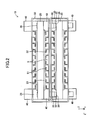
- the fuel cell 10 includes plural stacked bodies 20, each having the same shape, and plural interconnectors 30, each having the same shape. Each of the stacked bodies 20 is accommodated as being held by the corresponding single interconnector 30.
- the fuel cell 10 is formed by stacking the plural interconnectors 30, each of which accommodates the corresponding stacked body 20. Specifically, the fuel cell 10 has a stack structure.
- the stacked body of the plural interconnectors 30 corresponds to the "current-collector holding member".
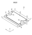
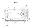
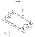
- the stacked body 20 schematically has a box-like shape (a sheet body shape having a thickness in the z-axis direction) having sides along the x-, y-, and z-axes.
- the length A1 of the side (long side) along the x-axis direction, the length B1 of the side (short side) along the y-axis direction, and the thickness Z1 are respectively 30 to 300 mm, 15 to 150 mm, and 0.5 to 5 mm in the present embodiment (see FIG. 6 ).
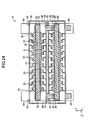
- the stacked body 20 includes a fuel electrode layer 21, an electrolyte layer 22, and a pair of air electrode layers 23.
- the fuel electrode layer 21 has a box-like shape (a sheet body shape having a thickness in the z-axis direction) having sides along the x-, y-, and z-axes.
- the fuel electrode layer 21 includes a fuel-electrode current-collecting layer 21a serving as a substrate, and fuel-electrode active layers 21b formed respectively on the upper and lower surfaces of the fuel-electrode current-collecting layer 21 a.
- a fuel channel 24 through which a fuel gas (e.g., hydrogen gas) flows is provided in the fuel-electrode current-collecting layer 21 a (see FIG. 7 , in particular).
- the electrolyte layer 22 is a thin film that is formed on the surface of the fuel electrode layer 12 so as to enclose the surrounding (upper, lower, and side faces) of the fuel electrode layer 21.
- the pair of the air electrode layers 23 are formed respectively on the upper surface of the electrolyte layer 22 formed on the upper surface of the fuel electrode layer 21 (more specifically, formed on the upper surface of the fuel-electrode active layer 21 b formed on the upper surface of the fuel-electrode current-collecting layer 21 a), and on the lower surface of the electrolyte layer 22 formed on the lower surface of the fuel electrode layer 21 (more specifically, formed on the lower surface of the fuel-electrode active layer 21 b formed on the lower surface of the fuel-electrode current-collecting layer 21 a).
- Each of the pair of the air electrode layers 23 has a same sheet-body shape having a thickness in the z-axis direction.
- the pair of the air electrode layers 23 is formed with a pair of cutout portions 23a and 23a for avoiding the interference with a pair of through-holes 25 and 25 that is described later.
- the fuel-electrode current-collecting layer 21 a is a porous fired body formed from Ni, YSZ (yttria-stabilized zircon), and zircon (ZrSiO 4 ) (after a later-described reduction process).
- the fuel-electrode active layer 21 b is a porous fired body formed from Ni and YSZ (after a later-described reduction process).
- the fuel electrode layer 21 serves as a fuel electrode (anode electrode).
- the electrolyte layer 22 is a dense fired body of YSZ.
- Each of the air electrode layers 23 is a porous fired body formed from LSCF (La0.6Sr0.4Co0.2Fe0.803: lanthanum strontium cobalt ferrite), and it serves as an air electrode (cathode electrode).
- a reaction preventing layer such as celia (CeO 2 ) may be provided between the electrolyte layer 22 and the air electrode layer 23.
- the celia include GDC (gadolinium-doped celia), SDC (samarium-doped celia), etc.
- the stacked body 20 has a room-temperature-to-1000 °C mean thermal expansion coefficient of about 12.8 ppm/K as a whole.
- the stacked body 20 is provided with a pair of through-holes 25 and 25.
- Each of the through-holes 25 is formed in the vicinity of the corresponding short side of the stacked body 20 and at the central part of this side.
- Each of the through-holes 25 extends through the electrolyte layer 23, and the fuel electrode layer 22.
- the paired cell through-holes 25 are communicated with each other through the fuel channel 24 in the fuel electrode layer 21 (see FIG. 7 , in particular).
- a heat-resistant metal is used for the material of the conductive plate 26, for example.
- Preferable heat-resistant metal includes ZMG material (made by Hitachi Metals, Ltd.), which is a ferrite stainless for a fuel cell.
- a conductive ceramic is used as the material of the conductive plate 26.
- a lanthanum chromite is preferable for the conductive ceramic.
- each of the conductive plates 26 is exposed to the outside.
- the conductive plate 26 functions as an electrically-connecting portion to a later-described leg part 34 of the interconnector 30 that is adjacent to the interconnector 30, which accommodates the conductive plate 26, from above.
- the stacked body 20 will be described later in more detail.
- the interconnector 30 will next be described with reference to FIGS. 2 to 4 and 8 and 9 .
- the interconnector 30 is divided into a first part 30A and a second part 30B that have a symmetric shape with respect to a plane parallel with the x-z plane at the center in the y-axis direction.
- the interconnector 30 may be handled as an integrated member composed of the first and the second parts 30A and 30B.
- the interconnector 30 is schematically a frame member (housing member) having a box-like shape (a sheet body shape having a thickness in the z-axis direction) having sides along the x-, y-, and z-axes and made of a conductive member.
- the length A2 of the side (long side) along the x-axis direction, the length B2 of the side (short side) along the y-axis direction, and the thickness Z2 are respectively 40 to 310 mm, 25 to 160 mm, and 3 to 8 mm in the present embodiment (see FIG. 9 ).
- the interconnector 30 is made of ZMG material (made by Hitachi Metals, Ltd.), which is a ferrite stainless for a fuel cell.
- the interconnector 30 has a room-temperature-to-1000 °C mean thermal expansion coefficient of about 12.5 ppm/K. Therefore, the thermal expansion coefficient of the interconnector 30 is substantially equal to the thermal expansion coefficient of the stacked body 20. As a result, even when the temperature of the fuel cell 10 changes, the difference in the amount of expansion and contraction is difficult to be produced between the stacked body 20 and the interconnector 30.
- a space open (extending) in the y-axis direction for accommodating the stacked body 20 is formed in the interconnector (e.g., the frame member) 30.
- a pair of cutout portions 31, 31 is formed at the interconnector 30, which accommodates the stacked body 20, in order to avoid the interference with a later-described pair of coupling members 40.
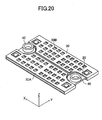
- Plural projections 32 that project upward or downward from the edge of a small window (through-hole) are formed respectively on the portion corresponding to the upper surface and the lower surface of the frame constituting the interconnector 30. As described later, these projections 32 function as electrically-connecting portions to the air electrode layer 23 of the stacked body 20 accommodated in the interconnector 30.
- Windows 33 are formed at four corners of the portion corresponding to the top surface of the frame, which constitutes the interconnector 30, and at the positions corresponding to the conductive plates 26 on the x-y plane in the state in which the stacked body 20 is accommodated.
- Leg portions 34 projecting downward are formed at four corners of the portion corresponding to the bottom surface of the frame, which constitutes the interconnector 30, and at the positions corresponding to the windows 33 on the x-y plane. When viewed from the z-axis direction, the entire leg portion 34 is included in the window 33. As described later, these leg portions 34 function as electrically-connecting portions to the conductive plates 26 of the stacked body 20 accommodated in the interconnector 30 adjacent to the interconnector from below, in the above-mentioned stacked state.
- the fuel cell 10 has a stack structure in which the plural interconnectors 30, each of which has the above-mentioned structure and accommodates and holds the stacked body 20 having the above-mentioned structure, are stacked.
- cylindrical coupling members 40, 40 each having a through-hole 41, are mounted at the positions corresponding to the pair of through-holes 25, 25 on the x-y plane between two adjacent stacked bodies 20.
- the adjacent two stacked bodies are stacked via the coupling members 40, 40 as being separated in the z-axis direction with the distance corresponding to the height of the coupling member 40 (see FIG. 4 , in particular).
- the through-holes 41 and the through-holes 25 are alternately connected, whereby one fuel supply path extending continuously in the z-axis direction and one fuel exhaust path extending continuously in the z-axis direction are formed.
- the fuel supply path and the fuel exhaust path communicate with the fuel channel 24 in each of the stacked bodies 20.
- the pair of the air electrode layers 23, 23 of the stacked body 20 and the plural projections 32 of the interconnector 30, which accommodates the stacked body 20, are electrically bonded and fixed with a conductive adhesive agent 51 (conductive paste) (see FIG. 3 , in particular).
- a conductive adhesive agent 51 conductive paste
- Four leg portions 34 of a certain interconnector 30 are inserted into the corresponding four windows of the interconnector 30 adjacent to the interconnector 30 from below.
- the conductive plates 26 (the top surface of the conductive plates 26) of a certain stacked body 20 and the leg portions 34 (the lower surfaces of the leg portions 34) of the interconnector 30 adjacent to the interconnector 30, which accommodates the stacked body 20, from above, are electrically bonded and fixed with a conductive adhesive agent 52 (conductive paste).
- the air electrode layer 23 of the upper one of the adjacent two stacked bodies 20 and the fuel electrode layer 21 of the lower one are electrically connected through the interconnector 30 that accommodates the upper stacked body 20.
- plural stacked bodies 20 are electrically connected in series in the whole fuel cell 10.
- the space formed between two adjacent stacked bodies 20 is utilized as an air channel S through which a gas containing oxygen (e.g., air) flows.
- a gas containing oxygen e.g., air
- the electrolyte layer 22 encloses the fuel electrode layer 21. Accordingly, the air channel S and the fuel channel 24 are separated only by the electrolyte layer 22.
- the working temperature of the fuel cell 10 is generally 600 °C or higher. Accordingly, the temperature of the fuel cell 10 is raised from room temperature to the working temperature (e.g., 800 °C) by means of an external heating mechanism (e.g., a heating mechanism that uses a resistance heater or a heating mechanism that utilizes heat generated through combustion of a fuel gas).
- an external heating mechanism e.g., a heating mechanism that uses a resistance heater or a heating mechanism that utilizes heat generated through combustion of a fuel gas.
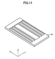
- a channel forming member 61 illustrated in FIG. 11 and having the shape same as that of the fuel channel 24 is prepared.
- the channel forming member 61 is formed by using a pore-forming agent (e.g., cellulose) with one of known methods.
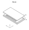
- a powder 62 that is to become a raw material of the fuel-electrode current-collecting layer 21 a is prepared.
- the powder 62 contains particles of NiO, YSZ, zircon, and pore-forming agent (e.g., cellulose) uniformly. The reason why the powder 62 contains the pore-forming agent is because the fuel electrode layer is made to be porous.
- FIG. 12 the powder 62 is pressed into a shape corresponding to the fuel-electrode current-collecting layer 21 a with the use of a (single-axis) pressing machine in order that the channel forming member 61 is embedded.
- a box-shaped powder compact 21az having the channel forming member 61 embedded therein is formed as illustrated in FIG. 13 .
- FIG. 14 is a sectional view of the powder compact 21 az taken long a plane that includes a line 14 - 14 of FIG. 13 and is parallel with the x-z plane.
- a YSZ-NiO paste film 21bz which is to become the fuel-electrode active layer 21 b later, is formed on the upper and lower surfaces of the powder compact 21az
- a YSZ paste film 22z which is to become the electrolyte layer 22 later, is formed around (at the upper, lower, and side surfaces of) the powder compact 21 az having the film 21bz formed thereon.
- the film 21bz may be formed in such a manner that a paste is applied onto the upper and lower surfaces of the powder compact 21 az or that a ceramic green sheet is adhered onto the upper and lower surfaces of the powder compact 21az.
- the film 22z may be formed in such a manner that a paste is applied around (at the upper, lower, and side surfaces of) the powder compact 21 az having the film 21bz formed thereon or that the surrounding (upper, lower, and side surfaces) of the powder compact 21az having the film 21bz formed thereon is covered by a ceramic green sheet.
- the powder compact 21 az having the film 21bz formed thereon can be covered by the ceramic green sheet in such a manner that the green sheet is adhered onto the upper and lower surfaces and the green sheet is wound around the side surface.
- a ceramic paste may further be applied onto the side surface of the film 22z, where a thermal stress is increased, for reinforcement.
- the member having the films 21bz and 22z formed thereon is fired at a predetermined temperature for a predetermined time (e.g., 1400°C for one hour).
- the channel forming member 61 is burnt down to form a fired body including the fuel electrode layer 21 (including the fuel-electrode current-collecting layer 21 a and fuel-electrode active layers 21 b formed respectively on the upper and lower surfaces of the fuel-electrode current-collecting layer 21 a) having the fuel channel 24 formed therein and the electrolyte layer 22 enclosing the fuel electrode layer 21 as illustrated in FIG. 16 . Since the pore-forming agent contained in the powder 62 is burnt down, the fuel electrode layer 21 is made to be porous.
- a paste film which is to become the reaction preventing layer later, is formed on the entire surface (upper, lower, and side surfaces) of the YSZ paste film 22z formed around the powder compact 21 az before the firing.
- This film is formed by applying a paste, or utilizing a ceramic green sheet, like the formation of the YSZ paste film 22z. This film and the YSZ paste film 22z are both fired.
- a paste film which is to become the reaction preventing layer later, may be formed by a printing process on only the upper and lower surfaces of the fired body, and then, this film may be fired.
- the pattern of this film is set such that the entire outline of the reaction preventing layer is present at the outside of the entire outline of the air electrode layer 23, as viewed from the z-axis direction. For example, it is adjusted such that the outline of this film is present at the outside of the outline of the later-described "a sheet 23z that is to become the air electrode layer 23 later" by about 1 mm.
- the sheet 23z that is to become the air electrode layer 23 later is formed on the upper and lower surfaces of the fired body with a printing process.
- This sheet 23z is fired at a predetermined temperature for a predetermined time (e.g., 1000°C for one hour).
- a predetermined temperature for a predetermined time e.g. 1000°C for one hour.
- the air electrode layers 23, 23 are formed on the upper and lower surfaces of the fired body.
- a pair of through-holes 25, 25 is formed on the fired body with one of know processing methods.
- four conductive plates 26 are arranged so as to be electrically connected to the internal fuel electrode layer 21 (more specifically, to the fuel-electrode active layer 21 b) of the fired body.
- the stacked body 20 is completed.
- the thus formed stacked bodies 20 are prepared in a required number.
- the interconnector 30 (actually, the first and second portions 30A and 30B) is formed by processing a thin plate, which is made of ZMG material (made by Hitachi Metals, Ltd.), which is a ferrite stainless for a fuel cell, into a shape illustrated in FIGS. 8 and 9 with a known method (etching, cutting, pressing, etc.)
- the formed interconnectors 30 (actually, the first and second portions 30A and 30B) are prepared in a required number.
- the coupling members 40 are bonded and fixed with an adhesive agent (e.g., a glass paste) at the position corresponding to the pair of through-holes 25, 25 on the top surface of each of the prepared plural sheet bodies 20. Further, a conductive paste (conductive adhesive agent 51) is applied onto the plural projections 32 of each of the interconnectors 30 (actually, the first and second portions 30A and 30B).
- an adhesive agent e.g., a glass paste
- each of the stacked bodies 20 to which the coupling members 40 are bonded and fixed is accommodated into the interconnector 30 (actually, the first and second portions 30A and 30B) having the conductive adhesive agent 51 applied thereon.
- the pair of air electrode layers 23, 23 of each stacked body 20 and the plural projections 32 of the interconnector 30, which accommodates the stacked body 20 are electrically connected and fixed by the conductive adhesive agent 51 (see FIG. 3 ).
- a conductive paste (conductive adhesive agent 52) is applied to the leg portions 34 (the lower surfaces of the leg portions 34) of each interconnector 30.
- the plural interconnectors 30 are stacked in such a manner that four windows 33 of a certain interconnector 30 have inserted therein four leg portions 34 of the interconnector 30 adjacent to the interconnector 30 from above.
- a stack structure is formed.
- the conductive plates 26 (the top surfaces of the conductive plates 26) and the leg portions 34 (the lower surfaces of the leg portions 34) of the interconnector 30 adjacent to the interconnector, which accommodates the stacked body 20, from above, are electrically connected and fixed with the conductive adhesive agent 52 (see FIG. 3 ).
- plural stacked bodies 20 are electrically connected in series. Further, bonding (sealing) between various coupling members is simultaneously performed in order to completely separate the fuel gas and air.
- a reduction process is performed to the fuel electrode layer 21 of each stacked body 20 in the stack structure.
- a heat treatment is performed to the stack structure, wherein the temperature of the stack structure is kept to be a predetermined temperature (e.g., 800°C) for a predetermined time.
- a reduction gas hydrogen gas in the present embodiment
- the fuel channel 24 and the air channel S are separated by the electrolyte layer 22. Accordingly, the supply of the reduction gas to the surface of the air electrode layer 23 can be prevented without taking a special measure for preventing the supply of the reduction gas to the surface of the air electrode layer 23 during the reduction process.
- NiO which is one of NiO, YSZ, and zircon constituting the fuel electrode layer 21
- the fuel electrode layer 21 becomes Ni-YSZ-zircon cermet that can function as the fuel electrode (anode electrode).
- the fuel electrode layer 21 includes the fuel-electrode current-collecting layer 21 a and the fuel-electrode active layers 21 b formed respectively on the upper and lower surfaces of the fuel-electrode current-collecting layer 21 a.
- the fuel-electrode current-collecting layer 21a (after the reduction process) is a porous layer made of fine particles of Ni, YSZ, and zircon (ZrSiO 4 )
- the diameters of each of the Ni particles, YSZ particles, and ZrSiO 4 particles contained in the fuel-electrode current-collecting layer 21 a are within the range of 0.3 to 1.5 ⁇ m, within the range of 0.5 to 2 ⁇ m, and within the range of 0.7 to 2.5 ⁇ m respectively in the present embodiment.
- the fuel-electrode active layer 21 b (after the reduction process) is a porous layer made of fine particles of Ni and YSZ.
- the diameters of each of the Ni particles, and YSZ particles contained in the fuel-electrode active layer 21 b are within the range of 0.3 to 1.5 ⁇ m, and within the range of 0.5 to 2 ⁇ m respectively in the present embodiment.
- the content percentage (volume %) of YSZ is greater in the fuel-electrode active layer 21 b than in the fuel-electrode current-collecting layer 21 a.
- the fuel -electrode current-collecting layer 21 a is mainly used for carrying electrons, which are obtained by the reaction represented by the formula (2), to the conductive plates 26, while the fuel-electrode active layer 21 b is mainly used to increase the speed of the reaction represented by the formula (2).
- the reason why the fuel-electrode active layer 21 b does not contain zircon particles is because the speed of the reaction represented by the formula (2) might be decreased, if zircon that is an insulating material is present in the vicinity of the interface between the fuel-electrode active layer 21 b and the electrolyte layer 22.
- the zircon particles are uniformly distributed (the distribution state of the zircon particles is homogenous) in the x-y plane direction and z-axis direction.
- the state in which "the zircon particles are uniformly distributed in the x-y plane direction (the distribution state of the zircon particles is homogenous)" means that the contained amount of the zircon particles per unit volume is uniform all over the x-y plane direction at any positions in the z-axis direction.
- the state in which "the zircon particles are uniformly distributed in the z-axis direction (the distribution state of the zircon particles is homogenous)" means that the contained amount of the zircon particles per unit volume is uniform all over the z-axis direction at any positions in the x-y plane direction. Specifically, the contained amount of the zircon particles per unit volume in the fuel-electrode current-collecting layer 21a is uniform therein, and the contained amount thereof is 3 to 30 vol.% in this embodiment.
- the contained amounts of Ni and YSZ in the fuel-electrode current-collecting layer 21 a are 35 to 55 vol.% and 15 to 62 vol.% respectively.
- the contained amounts of Ni and YSZ in the fuel-electrode active layer 21 b are 25 to 45 vol.% and 55 to 72 vol.% respectively.
- the electrolyte layer 22 is a dense layer made of fine YSZ particles.
- the diameter of the YSZ particle contained in the electrolyte layer 22 is 0.3 to 3 ⁇ m in the present embodiment.
- the particle diameter can be adjusted by the additive amount of Y203 to YSZ or firing temperature.
- the air electrode layer 23 is a porous layer made of fine LSCF particles.
- the diameter of the LSCF particle contained in the air electrode layer 23 is 0.2 to 2 ⁇ m in the present embodiment.
- the thickness Z1 of the stacked body 20 is uniform all over. In the present embodiment, the thickness Z1 is 0.5 to 5 mm as described above in the present embodiment.
- the thickness Za of the fuel electrode layer 21 is 500 to 3000 ⁇ m
- the thickness Zb of the electrolyte layer 22 is 1 to 20 ⁇ m
- the thickness Zc of the air electrode layer 23 is 3 to 50 ⁇ m.
- the thickness Za1 of the fuel-electrode current-collecting layer 21a is 500 to 3000 ⁇ m
- the thickness Za2 of the fuel-electrode active layer 21 b is 3 to 30 ⁇ m, respectively, for example
- the room-temperature-to-1000°C mean thermal expansion coefficients of the fuel electrode layer 21, the electrolyte layer 22, and the air electrode layer 23 are 11.5 to 13 ppm/K, 10 to 11.5 ppm/K, and 10 to 14 ppm/K, respectively.
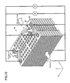
- the fuel electrode layer 21 is contracted by an amount corresponding to the amount of O (oxygen) that is removed from the fuel electrode layer 21 when NiO in the fuel electrode layer 21 is converted into Ni. As a result, the whole stacked body 20 is contracted. This contraction is referred to as "reduction contraction" below. The size of the stacked body 20 is reduced due to the reduction contraction.
- the reduction in the size of the stacked body 20 caused by the reduction contraction produces a deviation in the relative positional relationship on the x-y plane between the conductive plates 26 of the stacked body 20 and the leg portions 34 of the interconnector 30, which are electrically connected and fixed to each other, and on the x-y plane between the portions of the air electrode layers 23 of the stacked body 20 and the projections 32 of the interconnector 30, which are electrically connected and fixed to each other.
- FIG. 22 illustrates the case in which some of the plural projections 32 of the interconnector 30 are separated from the conductive adhesive agents 51, resulting in that the electrical connection between some of the projections 32 and the air electrode layer 23 is lost (refer to the portion encircled by a broken line in FIG. 22 ).
- the degree of the reduction contraction is suppressed by the fuel electrode layer 21 (fuel-electrode current-collecting layer 21 a) containing zircon, compared to the fuel electrode layer 21 not containing zircon (i.e., the fuel electrode layer 21 in which the fuel-electrode current-collecting layer 21 a and the fuel-electrode active layer 21 b are both made of only Ni and YSZ).
- the above-mentioned deviation in the relative positional relationship is more decreased when zircon is contained in the fuel electrode layer 21 (fuel-electrode current-collecting layer 21 a) as in the present embodiment, than in the case in which the zircon is not contained in the fuel electrode layer 21, whereby the situation in which the electrical connection is lost at a part of the electrically-connected portion between the stacked body 20 and the interconnector 30 is difficult to occur.
- the situation in which the output from the fuel cell 10 as a whole is decreased can be prevented.
- the "effect of suppressing the reduction contraction" described above can more surely be exhibited by setting the thickness of the "fuel-electrode active layer 21 b not containing zircon” to be sufficiently smaller than the thickness of "the fuel-electrode current-collecting layer 21 containing zircon” (i.e., by increasing the area, containing zircon, in the entire fuel electrode layer 21).
- the contained amounts of Ni in the standards 1 to 10 are fixed to be 45 vol.%.
- the contained amounts of zircon in the standards 1 to 10 are adjusted to be 10 types of different values within the range of 0 to 40 vol.% under the condition in which the sum of the contained amount of YSZ and the contained amount of zircon is fixed to be 55 vol.%.
- the stacked body used for this experiment had a box shape, wherein the length A1 of the long side was 120 mm, the length B1 of the short side was 60 mm, and the thickness Z1 was 1.5 mm (see FIG. 6 ).
- the electrolyte layer was formed in such a manner that a film of 3YSZ having a thickness of 5 ⁇ m was formed on the surface of the fuel electrode layer (powder compact), and this film was fired under 1400 °C for 1 hr.
- a reaction preventing layer made of GDC was interposed between the electrolyte layer and the air electrode layer.
- the reaction preventing layer was formed in such a manner that a film made of GDC having a thickness of 5 ⁇ m was formed on the surface of the electrolyte layer with a printing method, and this film was fired under 1350 °C for 1 hr.
- the air electrode layer was formed in such a manner that a film of LSCF having a thickness of 30 ⁇ m was formed on the surface of the reaction preventing layer with the printing method, and this film was fired under 1000 °C for 1 hr.
- a value at 750 °C which was obtained by using one of known impedance analysis methods, was employed as the resistance value.
- the electrically connected state at the electrically connected portion was confirmed by the process described below. Firstly, the stack structure, whose temperature was lowered, was immersed into a zirconia slurry. Then, the stack structure was dried at 120 °C. After being dried, the stack structure was disassembled to confirm whether the white slurry enters the electrically connected portion or not. The condition in which the slurry does not enter means that the connection state is normal, while the condition in which the slurry enters means that the connection state is abnormal.
- those having the contained amount of zircon of 3 to 30 vol.% (i.e., standards 3 to 8) in the above-mentioned embodiments have the resistance values apparently smaller and have the output density apparently greater than those of the others (i.e., standards 1, 2, 9, 10). Further, the connection state at the electrically connected portion is also normal. This means that, even if the amount of O (oxygen) removed from the fuel electrode layer 21 is the same, the degree of the reduction contraction is more reduced in the standards 3 to 8 in which the zircon is contained in the fuel electrode layer 21 (fuel-electrode current-collecting layer 21 a) in an appropriate amount, than in the case in which the zircon is not contained.
- O oxygen
- the condition in which the resistance value is great and the output density is small in the standards 1 and 2 is caused because the electrical connection is lost at a part of the electrically connected portion. This means that the degree of the reduction contraction cannot be decreased, because the contained amount of zircon is too small.
- the condition in which the resistance value is great and the output density is small in the standards 9 and 10 is caused because the resistance value of the fuel electrode layer itself is great due to the excessively great contained amount of zircon.
- the solid oxide fuel cell (SOFC) 10 having the stack structure according to the embodiment of the present invention has the stack structure in which plural interconnectos 30, each of which accommodates the corresponding stacked body 20, are stacked.
- Each of the stacked bodies 20 includes the fuel electrode layer 21, which has the fuel channel 24 formed therein and which serves as an anode electrode, the electrolyte layer 22, and the air electrode layer 23 that serves as a cathode electrode.
- the fuel electrode layer 21 contains zircon (ZrSiO 4 ). Accordingly, the degree of contraction of the fuel electrode layer 21, which contraction is caused when the reduction process is executed to the fuel electrode layer 21 in order to allow the fuel electrode layer 21 to serve as the anode electrode, is reduced.
- the present invention can prevent the occurrence of the situation in which the electrical connection is lost at a part of the electrically connected portion between the stacked body 20 and the interconnector 30, which is caused by the above-mentioned contraction, in case where the reduction process is performed to each of the fuel electrode layers 21 in the assembled stack structure.
- the fuel electrode layer includes two layers that are the layer (fuel-electrode active layer) not containing zircon and the layer (fuel-electrode current-collecting layer) containing zircon.
- the fuel electrode layer includes two or more layers, each of which contains zircon and has the different contained amount of zircon.
- the zircon particles may uniformly be distributed in each of the layers containing zircon, or it may be configured such that the zircon particles are uniformly distributed in the x-y plane direction and the contained amount of the zircon particles (contained amount of zircon) per unit volume is gradually changed in the z-axis direction.
- the fuel electrode layer 21 may include only one layer containing zircon.
- the zircon particles may be distributed uniformly or non-uniformly.
- the electrolyte layer 22 is formed on the surface of the fuel electrode layer 21 so as to enclose the surrounding (upper, lower, and side surfaces) of the fuel electrode layer 21 in the stacked body 20.
- the electrolyte layer may be formed only on the upper and lower surfaces of the fuel electrode layer 21, and not formed on the side faces (four faces) of the fuel electrode layer.
- the side faces of the fuel electrode layer 21 (or the entire side faces of the stacked body 20) has to be covered by a side wall, instead of the electrolyte layer, that has a function of separating the air channel S and the fuel channel 24. in this case, a glass material is used as the side wall.
- the portion in the fuel electrode layer 21 other than the portion containing zircon can be formed from, for example, platinum, platinum-zirconia cermet, platinum-cerium-oxide cermet, ruthenium, or ruthenium-zirconia cermet.
- the air electrode layer 23 can be formed from, for example, lanthanum-containing perovskite-type complex oxide (e.g., lanthanum manganite, lanthanum cobaltite, or lanthanum ferrite, in addition to the above-mentioned lanthanum strontium cobalt ferrite).
- Lanthanum cobaltite, lanthanum manganite and lanthanum ferrite may be doped with strontium, calcium, chromium, cobalt, iron, nickel, aluminum, or the like.
- the air electrode layer 23 may be formed from palladium, platinum, ruthenium, platinum-zirconia cermet, palladium-zirconia cermet, ruthenium-zirconia cermet, platinum-cerium-oxide cermet, palladium-cerium-oxide cermet, or ruthenium-cerium-oxide cermet.
- the shape of the x-y plane of the stacked body 20 is rectangular.
- the stacked body 20 may have a planar shape of square, circle, ellipse, etc.
- the diameter, when it is circle, the major axis, when it is elliptic, and the length of one side, when it is square is 3 cm or more.
- the fuel-electrode current-collecting layer 21a is a porous fired body formed from Ni, YSZ (yttria-stabilized zircon), and zircon (ZrSiO 4 ) (after the reduction process).
- the fuel-electrode current-collecting layer 21a may a porous fired body formed from Ni, Y 2 O 3 (yttria), and zircon (ZrSiO 4 ) (after the reduction process).
- the upper and the lower surfaces of the powder compact 21 az which is to become the fuel-electrode current-collecting layer 21 a afterward, are shown as a plane as illustrated in FIGS. 13 and 14 .
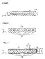
- the upper and lower surfaces of the powder compact 21 az are formed with irregularities corresponding to the shape of the channel forming member 61 in such a manner that the thickness of the portion corresponding to the area where the channel forming member 61 is present is greater than the thickness of the portion corresponding to the other areas as viewed from the z-axis direction, as illustrated in FIGS. 25 and 26 , because of the difference in the contraction property between the channel forming member 61 and the powder 62 during the press molding.
- the similar irregularities are also formed, as illustrated in FIG. 27 , on the upper and lower surfaces of the stacked body formed with the use of the powder compact 21 az that has the irregularities formed on the upper and lower surfaces.
- the height Z3 of the fuel channel 24 is 100 to 500 ⁇ m
- the thickness Z4 of the portion corresponding to the area where the fuel channel 24 is not present is 1000 to 1500 ⁇ m as viewed from the z-axis direction
- the thickness Z5 of the portion corresponding to the area where the fuel channel 24 is present is 1100 to 2000 ⁇ m as viewed from the z-axis direction.
- the stacked body illustrated in FIG. 27 has a feature such that, as viewed from the thickness direction, the thickness of the portion of the fuel electrode layer corresponding to the area where the fuel gas channel is present is greater than the thickness of the portion corresponding to the area where the fuel gas channel is not present, and the thickness of the portion of the stacked body corresponding to the area where the fuel gas channel is present is greater than the thickness of the portion corresponding to the area where the fuel gas channel is not present.
- the similar irregularities are formed on the portion of the electrolyte layer 22, which encloses the surrounding of the fuel electrode layer 21, corresponding to the upper and lower surfaces of the stacked body. Since the irregularities are formed on the electrolyte layer 22 as described above, the rigidity of the electrolyte layer 22 with respect to the deformation is increased, compared to the case in which the irregularities are not formed. As a result, even if the fuel electrode layer 21, which is enclosed by the electrolyte layer 22, tends to contract due to the reduction process, this contraction (i.e., reduction contraction) can be suppressed.
- the thickness of the portion of the fuel-electrode current-collecting layer 21a corresponding to the area where the fuel channel 24 is formed is likely to be small as viewed from the z-axis direction. As a result, the strength of the entire stacked body is likely to be insufficient.
- the irregularities are formed on the upper and lower surfaces of the stacked body, the rigidity of the entire stacked body with respect to the deformation is increased. Consequently, the strength of the stacked body can be maintained.
Landscapes
- Chemical & Material Sciences (AREA)
- Engineering & Computer Science (AREA)
- Chemical Kinetics & Catalysis (AREA)
- Electrochemistry (AREA)
- General Chemical & Material Sciences (AREA)
- Manufacturing & Machinery (AREA)
- Life Sciences & Earth Sciences (AREA)
- Composite Materials (AREA)
- Sustainable Development (AREA)
- Sustainable Energy (AREA)
- Ceramic Engineering (AREA)
- Materials Engineering (AREA)
- Fuel Cell (AREA)
- Inert Electrodes (AREA)
Applications Claiming Priority (2)
| Application Number | Priority Date | Filing Date | Title |
|---|---|---|---|
| JP2009154597 | 2009-06-30 | ||
| JP2010100489A JP5631625B2 (ja) | 2009-06-30 | 2010-04-26 | 固体酸化物形燃料電池 |
Publications (2)
| Publication Number | Publication Date |
|---|---|
| EP2273595A1 true EP2273595A1 (de) | 2011-01-12 |
| EP2273595B1 EP2273595B1 (de) | 2014-02-26 |
Family
ID=42782070
Family Applications (1)
| Application Number | Title | Priority Date | Filing Date |
|---|---|---|---|
| EP10251110.2A Not-in-force EP2273595B1 (de) | 2009-06-30 | 2010-06-17 | Festoxidbrennstoffzelle |
Country Status (3)
| Country | Link |
|---|---|
| US (1) | US20100330457A1 (de) |
| EP (1) | EP2273595B1 (de) |
| JP (1) | JP5631625B2 (de) |
Families Citing this family (11)
| Publication number | Priority date | Publication date | Assignee | Title |
|---|---|---|---|---|
| GB2277012B (en) | 1993-04-08 | 1997-06-18 | Sony Uk Ltd | Image data storage |
| TWI472090B (zh) | 2011-04-22 | 2015-02-01 | Univ Nat Cheng Kung | Fuel cell solid electrolyte structure |
| KR20130030116A (ko) * | 2011-09-16 | 2013-03-26 | 삼성에스디아이 주식회사 | 막전극 조립체 및 연료전지 스택 |
| KR101278316B1 (ko) * | 2011-11-30 | 2013-06-25 | 삼성전기주식회사 | 고체산화물 연료 전지 |
| JP2013214398A (ja) * | 2012-04-02 | 2013-10-17 | Konica Minolta Inc | 燃料電池システムの製造方法 |
| JP6293418B2 (ja) * | 2013-03-08 | 2018-03-14 | 日本特殊陶業株式会社 | 固体電解質型燃料電池用電極及び固体電解質型燃料電池セル |
| CN110344747B (zh) * | 2014-08-18 | 2020-11-24 | 兰普控股私人有限公司 | 伸缩梯子组件 |
| KR102123714B1 (ko) | 2016-08-16 | 2020-06-16 | 주식회사 엘지화학 | 평판형 고체 산화물 연료전지 |
| JP6724881B2 (ja) * | 2017-10-20 | 2020-07-15 | 株式会社村田製作所 | 固体電解コンデンサの製造方法、及び、固体電解コンデンサ |
| CN116111158A (zh) * | 2021-11-11 | 2023-05-12 | 博隆能源股份有限公司 | 包含改良介电层的燃料电池堆 |
| KR102864729B1 (ko) * | 2022-10-14 | 2025-09-26 | 한국에너지기술연구원 | 고체 산화물 연료 전지용 연료극 지지체 및 이를 포함하는 고체 산화물 연료 전지 |
Citations (10)
| Publication number | Priority date | Publication date | Assignee | Title |
|---|---|---|---|---|
| JPH05251095A (ja) * | 1992-03-06 | 1993-09-28 | Murata Mfg Co Ltd | 固体電解質型燃料電池 |
| DE19630210A1 (de) * | 1996-07-26 | 1998-01-29 | Dornier Gmbh | Brenngaselektrode für elektrochemische Zellen |
| JPH10228911A (ja) * | 1996-12-11 | 1998-08-25 | Mitsubishi Heavy Ind Ltd | 固体電解質燃料電池用電極材料 |
| EP1122806A1 (de) * | 2000-02-02 | 2001-08-08 | Haldor Topsoe A/S | Festoxid-Brennstoffzelle |
| JP2007012498A (ja) * | 2005-07-01 | 2007-01-18 | Chubu Electric Power Co Inc | 固体酸化物形燃料電池用燃料電極の製造方法及び燃料電池 |
| WO2007029860A1 (ja) | 2005-09-07 | 2007-03-15 | Ngk Insulators, Ltd. | 電気化学デバイスおよび電気化学装置 |
| EP1858106A2 (de) * | 2006-04-24 | 2007-11-21 | Ngk Insulators, Ltd. | Dünnes Keramikplattenelement |
| EP1919021A2 (de) * | 2006-10-24 | 2008-05-07 | Ngk Insulators, Ltd. | Dünnes Plattenelement für die Einheitszelle einer Festoxidbrennstoffzelle |
| EP1998396A2 (de) * | 2007-05-22 | 2008-12-03 | Ngk Insulators, Ltd. | Festoxidbrennstoffzelle |
| EP2157651A1 (de) * | 2008-08-21 | 2010-02-24 | Ngk Insulators, Ltd. | Blattkörper aus einer Festoxidbrennstoffzelle und Festoxidbrennstoffzelle |
Family Cites Families (17)
| Publication number | Priority date | Publication date | Assignee | Title |
|---|---|---|---|---|
| US5141825A (en) * | 1991-07-26 | 1992-08-25 | Westinghouse Electric Corp. | Method of making a cermet fuel electrode containing an inert additive |
| JPH10172578A (ja) * | 1996-12-13 | 1998-06-26 | Mitsubishi Heavy Ind Ltd | 固体電解質型電気化学セルの燃料極材料 |
| JP3724762B2 (ja) * | 1997-07-11 | 2005-12-07 | 日本電信電話株式会社 | 固体電解質型燃料電池の燃料電極の製造方法 |
| US6228521B1 (en) * | 1998-12-08 | 2001-05-08 | The University Of Utah Research Foundation | High power density solid oxide fuel cell having a graded anode |
| JP3858261B2 (ja) * | 2001-05-22 | 2006-12-13 | 日産自動車株式会社 | 燃料電池用セル板、その製造方法および固体電解質型燃料電池 |
| JP3661676B2 (ja) * | 2001-11-07 | 2005-06-15 | 東陶機器株式会社 | 固体電解質型燃料電池 |
| US7736772B2 (en) * | 2002-02-14 | 2010-06-15 | Alberta Research Council, Inc. | Tubular solid oxide fuel cell stack |
| JP4552371B2 (ja) * | 2002-03-11 | 2010-09-29 | 三菱マテリアル株式会社 | 固体電解質型燃料電池 |
| WO2004082058A1 (ja) * | 2003-03-13 | 2004-09-23 | Tokyo Gas Company Limited | 固体酸化物形燃料電池モジュール |
| JP4367843B2 (ja) * | 2004-03-25 | 2009-11-18 | 日本碍子株式会社 | 燃料極、電気化学セルおよび燃料極の製造方法 |
| JP2006332027A (ja) * | 2005-04-27 | 2006-12-07 | Tokyo Gas Co Ltd | 改質器一体型燃料電池 |
| JP4863657B2 (ja) * | 2005-06-28 | 2012-01-25 | 京セラ株式会社 | 燃料電池セル及び燃料電池スタック並びに燃料電池 |
| JP4596158B2 (ja) * | 2005-09-07 | 2010-12-08 | Toto株式会社 | 固体酸化物形燃料電池 |
| JP5288686B2 (ja) * | 2006-01-27 | 2013-09-11 | 京セラ株式会社 | 燃料電池用導電性焼結体及び燃料電池セル、燃料電池 |
| JP4819568B2 (ja) * | 2006-05-02 | 2011-11-24 | 日本電信電話株式会社 | 固体酸化物形燃料電池及びその作製方法 |
| JP5207267B2 (ja) * | 2006-09-19 | 2013-06-12 | 日本碍子株式会社 | 電気化学セル |
| JP2009016109A (ja) * | 2007-07-03 | 2009-01-22 | Tokyo Electric Power Co Inc:The | 固体酸化物形燃料電池用セル及び固体酸化物形燃料電池 |
-
2010
- 2010-04-26 JP JP2010100489A patent/JP5631625B2/ja not_active Expired - Fee Related
- 2010-06-16 US US12/816,619 patent/US20100330457A1/en not_active Abandoned
- 2010-06-17 EP EP10251110.2A patent/EP2273595B1/de not_active Not-in-force
Patent Citations (10)
| Publication number | Priority date | Publication date | Assignee | Title |
|---|---|---|---|---|
| JPH05251095A (ja) * | 1992-03-06 | 1993-09-28 | Murata Mfg Co Ltd | 固体電解質型燃料電池 |
| DE19630210A1 (de) * | 1996-07-26 | 1998-01-29 | Dornier Gmbh | Brenngaselektrode für elektrochemische Zellen |
| JPH10228911A (ja) * | 1996-12-11 | 1998-08-25 | Mitsubishi Heavy Ind Ltd | 固体電解質燃料電池用電極材料 |
| EP1122806A1 (de) * | 2000-02-02 | 2001-08-08 | Haldor Topsoe A/S | Festoxid-Brennstoffzelle |
| JP2007012498A (ja) * | 2005-07-01 | 2007-01-18 | Chubu Electric Power Co Inc | 固体酸化物形燃料電池用燃料電極の製造方法及び燃料電池 |
| WO2007029860A1 (ja) | 2005-09-07 | 2007-03-15 | Ngk Insulators, Ltd. | 電気化学デバイスおよび電気化学装置 |
| EP1858106A2 (de) * | 2006-04-24 | 2007-11-21 | Ngk Insulators, Ltd. | Dünnes Keramikplattenelement |
| EP1919021A2 (de) * | 2006-10-24 | 2008-05-07 | Ngk Insulators, Ltd. | Dünnes Plattenelement für die Einheitszelle einer Festoxidbrennstoffzelle |
| EP1998396A2 (de) * | 2007-05-22 | 2008-12-03 | Ngk Insulators, Ltd. | Festoxidbrennstoffzelle |
| EP2157651A1 (de) * | 2008-08-21 | 2010-02-24 | Ngk Insulators, Ltd. | Blattkörper aus einer Festoxidbrennstoffzelle und Festoxidbrennstoffzelle |
Also Published As
| Publication number | Publication date |
|---|---|
| JP2011029153A (ja) | 2011-02-10 |
| EP2273595B1 (de) | 2014-02-26 |
| US20100330457A1 (en) | 2010-12-30 |
| JP5631625B2 (ja) | 2014-11-26 |
Similar Documents
| Publication | Publication Date | Title |
|---|---|---|
| EP2273595B1 (de) | Festoxidbrennstoffzelle | |
| EP0513982A2 (de) | Verfahren zur Herstellung einer Festoxid-Schicht und Verfahren zur Herstellung einer Festoxid-Brennstoffzelle unter Verwendung der Festoxid-Schicht | |
| US8304136B2 (en) | Solid oxide fuel cell and solid oxide fuel cell bundle | |
| US10665870B2 (en) | Electrochemical reaction unit and fuel cell stack | |
| US20180123143A1 (en) | Electrochemical reaction unit and fuel cell stack | |
| US8968962B2 (en) | Solid oxide fuel cell, and assembling method of the same | |
| EP3561928A1 (de) | Zelle, zellenstapelvorrichtung, modul und modulgehäuse | |
| US8999607B2 (en) | Manufacturing method of solid oxide fuel cell, and manufacturing method of compact of divided member of the cell | |
| CN111146445B (zh) | 燃料电池、燃料电池堆、以及它们的制造方法 | |
| JP7245036B2 (ja) | 燃料電池スタックおよびその製造方法 | |
| EP2157651B1 (de) | Blattkörper aus einer Festoxidbrennstoffzelle und Festoxidbrennstoffzelle | |
| JP6162572B2 (ja) | 固体酸化物形燃料電池単セルの製造方法及び固体酸化物形燃料電池スタックの製造方法 | |
| US8377611B2 (en) | Assembling method of solid oxide fuel cell | |
| CN111244498B (zh) | 燃料电池和燃料电池堆 | |
| KR20180093087A (ko) | 연료 전지 발전 단위 및 연료 전지 스택 | |
| JP4781823B2 (ja) | 円筒横縞型燃料電池 | |
| JP7256309B2 (ja) | セル及びセルスタック装置 | |
| EP3979378B1 (de) | Zelle, zellenstapelvorrichtung, modul und modulgehäuse | |
| JP5502365B2 (ja) | 固体酸化物形燃料電池用ハーフセル、固体酸化物形燃料電池および固体酸化物形燃料電池用ハーフセルの製造方法 | |
| JPH11126617A (ja) | 固体電解質型燃料電池とその製造方法 | |
| JP6861183B2 (ja) | 電気化学反応単セルの製造方法 | |
| JP2017010709A (ja) | 燃料電池単セルおよび燃料電池スタック | |
| JP5417344B2 (ja) | 電気化学装置 |
Legal Events
| Date | Code | Title | Description |
|---|---|---|---|
| PUAI | Public reference made under article 153(3) epc to a published international application that has entered the european phase |
Free format text: ORIGINAL CODE: 0009012 |
|
| AK | Designated contracting states |
Kind code of ref document: A1 Designated state(s): AL AT BE BG CH CY CZ DE DK EE ES FI FR GB GR HR HU IE IS IT LI LT LU LV MC MK MT NL NO PL PT RO SE SI SK SM TR |
|
| AX | Request for extension of the european patent |
Extension state: BA ME RS |
|
| 17P | Request for examination filed |
Effective date: 20110301 |
|
| 17Q | First examination report despatched |
Effective date: 20121106 |
|
| GRAJ | Information related to disapproval of communication of intention to grant by the applicant or resumption of examination proceedings by the epo deleted |
Free format text: ORIGINAL CODE: EPIDOSDIGR1 |
|
| GRAP | Despatch of communication of intention to grant a patent |
Free format text: ORIGINAL CODE: EPIDOSNIGR1 |
|
| RIC1 | Information provided on ipc code assigned before grant |
Ipc: H01M 8/12 20060101AFI20130816BHEP Ipc: H01M 8/24 20060101ALI20130816BHEP Ipc: H01M 4/90 20060101ALI20130816BHEP Ipc: H01M 8/02 20060101ALI20130816BHEP Ipc: H01M 4/86 20060101ALI20130816BHEP |
|
| GRAP | Despatch of communication of intention to grant a patent |
Free format text: ORIGINAL CODE: EPIDOSNIGR1 |
|
| INTG | Intention to grant announced |
Effective date: 20131002 |
|
| RAP1 | Party data changed (applicant data changed or rights of an application transferred) |
Owner name: NGK INSULATORS, LTD. |
|
| GRAS | Grant fee paid |
Free format text: ORIGINAL CODE: EPIDOSNIGR3 |
|
| GRAA | (expected) grant |
Free format text: ORIGINAL CODE: 0009210 |
|
| AK | Designated contracting states |
Kind code of ref document: B1 Designated state(s): AL AT BE BG CH CY CZ DE DK EE ES FI FR GB GR HR HU IE IS IT LI LT LU LV MC MK MT NL NO PL PT RO SE SI SK SM TR |
|
| REG | Reference to a national code |
Ref country code: GB Ref legal event code: FG4D |
|
| REG | Reference to a national code |
Ref country code: CH Ref legal event code: EP |
|
| REG | Reference to a national code |
Ref country code: AT Ref legal event code: REF Ref document number: 654047 Country of ref document: AT Kind code of ref document: T Effective date: 20140315 |
|
| REG | Reference to a national code |
Ref country code: IE Ref legal event code: FG4D |
|
| REG | Reference to a national code |
Ref country code: DE Ref legal event code: R096 Ref document number: 602010013726 Country of ref document: DE Effective date: 20140410 |
|
| REG | Reference to a national code |
Ref country code: NL Ref legal event code: VDEP Effective date: 20140226 |
|
| REG | Reference to a national code |
Ref country code: AT Ref legal event code: MK05 Ref document number: 654047 Country of ref document: AT Kind code of ref document: T Effective date: 20140226 |
|
| REG | Reference to a national code |
Ref country code: LT Ref legal event code: MG4D |
|
| PG25 | Lapsed in a contracting state [announced via postgrant information from national office to epo] |
Ref country code: IS Free format text: LAPSE BECAUSE OF FAILURE TO SUBMIT A TRANSLATION OF THE DESCRIPTION OR TO PAY THE FEE WITHIN THE PRESCRIBED TIME-LIMIT Effective date: 20140626 Ref country code: LT Free format text: LAPSE BECAUSE OF FAILURE TO SUBMIT A TRANSLATION OF THE DESCRIPTION OR TO PAY THE FEE WITHIN THE PRESCRIBED TIME-LIMIT Effective date: 20140226 Ref country code: NO Free format text: LAPSE BECAUSE OF FAILURE TO SUBMIT A TRANSLATION OF THE DESCRIPTION OR TO PAY THE FEE WITHIN THE PRESCRIBED TIME-LIMIT Effective date: 20140526 |
|
| PG25 | Lapsed in a contracting state [announced via postgrant information from national office to epo] |
Ref country code: AT Free format text: LAPSE BECAUSE OF FAILURE TO SUBMIT A TRANSLATION OF THE DESCRIPTION OR TO PAY THE FEE WITHIN THE PRESCRIBED TIME-LIMIT Effective date: 20140226 Ref country code: SE Free format text: LAPSE BECAUSE OF FAILURE TO SUBMIT A TRANSLATION OF THE DESCRIPTION OR TO PAY THE FEE WITHIN THE PRESCRIBED TIME-LIMIT Effective date: 20140226 Ref country code: FI Free format text: LAPSE BECAUSE OF FAILURE TO SUBMIT A TRANSLATION OF THE DESCRIPTION OR TO PAY THE FEE WITHIN THE PRESCRIBED TIME-LIMIT Effective date: 20140226 Ref country code: NL Free format text: LAPSE BECAUSE OF FAILURE TO SUBMIT A TRANSLATION OF THE DESCRIPTION OR TO PAY THE FEE WITHIN THE PRESCRIBED TIME-LIMIT Effective date: 20140226 Ref country code: PT Free format text: LAPSE BECAUSE OF FAILURE TO SUBMIT A TRANSLATION OF THE DESCRIPTION OR TO PAY THE FEE WITHIN THE PRESCRIBED TIME-LIMIT Effective date: 20140626 Ref country code: CY Free format text: LAPSE BECAUSE OF FAILURE TO SUBMIT A TRANSLATION OF THE DESCRIPTION OR TO PAY THE FEE WITHIN THE PRESCRIBED TIME-LIMIT Effective date: 20140226 |
|
| PG25 | Lapsed in a contracting state [announced via postgrant information from national office to epo] |
Ref country code: HR Free format text: LAPSE BECAUSE OF FAILURE TO SUBMIT A TRANSLATION OF THE DESCRIPTION OR TO PAY THE FEE WITHIN THE PRESCRIBED TIME-LIMIT Effective date: 20140226 Ref country code: LV Free format text: LAPSE BECAUSE OF FAILURE TO SUBMIT A TRANSLATION OF THE DESCRIPTION OR TO PAY THE FEE WITHIN THE PRESCRIBED TIME-LIMIT Effective date: 20140226 Ref country code: BE Free format text: LAPSE BECAUSE OF FAILURE TO SUBMIT A TRANSLATION OF THE DESCRIPTION OR TO PAY THE FEE WITHIN THE PRESCRIBED TIME-LIMIT Effective date: 20140226 |
|
| PG25 | Lapsed in a contracting state [announced via postgrant information from national office to epo] |
Ref country code: RO Free format text: LAPSE BECAUSE OF FAILURE TO SUBMIT A TRANSLATION OF THE DESCRIPTION OR TO PAY THE FEE WITHIN THE PRESCRIBED TIME-LIMIT Effective date: 20140226 Ref country code: EE Free format text: LAPSE BECAUSE OF FAILURE TO SUBMIT A TRANSLATION OF THE DESCRIPTION OR TO PAY THE FEE WITHIN THE PRESCRIBED TIME-LIMIT Effective date: 20140226 Ref country code: CZ Free format text: LAPSE BECAUSE OF FAILURE TO SUBMIT A TRANSLATION OF THE DESCRIPTION OR TO PAY THE FEE WITHIN THE PRESCRIBED TIME-LIMIT Effective date: 20140226 Ref country code: DK Free format text: LAPSE BECAUSE OF FAILURE TO SUBMIT A TRANSLATION OF THE DESCRIPTION OR TO PAY THE FEE WITHIN THE PRESCRIBED TIME-LIMIT Effective date: 20140226 |
|
| REG | Reference to a national code |
Ref country code: DE Ref legal event code: R097 Ref document number: 602010013726 Country of ref document: DE |
|
| PG25 | Lapsed in a contracting state [announced via postgrant information from national office to epo] |
Ref country code: ES Free format text: LAPSE BECAUSE OF FAILURE TO SUBMIT A TRANSLATION OF THE DESCRIPTION OR TO PAY THE FEE WITHIN THE PRESCRIBED TIME-LIMIT Effective date: 20140226 Ref country code: SK Free format text: LAPSE BECAUSE OF FAILURE TO SUBMIT A TRANSLATION OF THE DESCRIPTION OR TO PAY THE FEE WITHIN THE PRESCRIBED TIME-LIMIT Effective date: 20140226 Ref country code: PL Free format text: LAPSE BECAUSE OF FAILURE TO SUBMIT A TRANSLATION OF THE DESCRIPTION OR TO PAY THE FEE WITHIN THE PRESCRIBED TIME-LIMIT Effective date: 20140226 |
|
| PLBE | No opposition filed within time limit |
Free format text: ORIGINAL CODE: 0009261 |
|
| STAA | Information on the status of an ep patent application or granted ep patent |
Free format text: STATUS: NO OPPOSITION FILED WITHIN TIME LIMIT |
|
| PG25 | Lapsed in a contracting state [announced via postgrant information from national office to epo] |
Ref country code: MC Free format text: LAPSE BECAUSE OF FAILURE TO SUBMIT A TRANSLATION OF THE DESCRIPTION OR TO PAY THE FEE WITHIN THE PRESCRIBED TIME-LIMIT Effective date: 20140226 Ref country code: LU Free format text: LAPSE BECAUSE OF FAILURE TO SUBMIT A TRANSLATION OF THE DESCRIPTION OR TO PAY THE FEE WITHIN THE PRESCRIBED TIME-LIMIT Effective date: 20140617 |
|
| REG | Reference to a national code |
Ref country code: CH Ref legal event code: PL |
|
| 26N | No opposition filed |
Effective date: 20141127 |
|
| REG | Reference to a national code |
Ref country code: DE Ref legal event code: R097 Ref document number: 602010013726 Country of ref document: DE Effective date: 20141127 |
|
| REG | Reference to a national code |
Ref country code: IE Ref legal event code: MM4A |
|
| REG | Reference to a national code |
Ref country code: FR Ref legal event code: ST Effective date: 20150227 |
|
| PG25 | Lapsed in a contracting state [announced via postgrant information from national office to epo] |
Ref country code: IT Free format text: LAPSE BECAUSE OF FAILURE TO SUBMIT A TRANSLATION OF THE DESCRIPTION OR TO PAY THE FEE WITHIN THE PRESCRIBED TIME-LIMIT Effective date: 20140226 |
|
| PG25 | Lapsed in a contracting state [announced via postgrant information from national office to epo] |
Ref country code: IE Free format text: LAPSE BECAUSE OF NON-PAYMENT OF DUE FEES Effective date: 20140617 Ref country code: CH Free format text: LAPSE BECAUSE OF NON-PAYMENT OF DUE FEES Effective date: 20140630 Ref country code: LI Free format text: LAPSE BECAUSE OF NON-PAYMENT OF DUE FEES Effective date: 20140630 |
|
| PG25 | Lapsed in a contracting state [announced via postgrant information from national office to epo] |
Ref country code: FR Free format text: LAPSE BECAUSE OF NON-PAYMENT OF DUE FEES Effective date: 20140630 Ref country code: SI Free format text: LAPSE BECAUSE OF FAILURE TO SUBMIT A TRANSLATION OF THE DESCRIPTION OR TO PAY THE FEE WITHIN THE PRESCRIBED TIME-LIMIT Effective date: 20140226 |
|
| PG25 | Lapsed in a contracting state [announced via postgrant information from national office to epo] |
Ref country code: MT Free format text: LAPSE BECAUSE OF FAILURE TO SUBMIT A TRANSLATION OF THE DESCRIPTION OR TO PAY THE FEE WITHIN THE PRESCRIBED TIME-LIMIT Effective date: 20140226 |
|
| PG25 | Lapsed in a contracting state [announced via postgrant information from national office to epo] |
Ref country code: SM Free format text: LAPSE BECAUSE OF FAILURE TO SUBMIT A TRANSLATION OF THE DESCRIPTION OR TO PAY THE FEE WITHIN THE PRESCRIBED TIME-LIMIT Effective date: 20140226 |
|
| PG25 | Lapsed in a contracting state [announced via postgrant information from national office to epo] |
Ref country code: BG Free format text: LAPSE BECAUSE OF FAILURE TO SUBMIT A TRANSLATION OF THE DESCRIPTION OR TO PAY THE FEE WITHIN THE PRESCRIBED TIME-LIMIT Effective date: 20140226 Ref country code: GR Free format text: LAPSE BECAUSE OF FAILURE TO SUBMIT A TRANSLATION OF THE DESCRIPTION OR TO PAY THE FEE WITHIN THE PRESCRIBED TIME-LIMIT Effective date: 20140527 |
|
| PG25 | Lapsed in a contracting state [announced via postgrant information from national office to epo] |
Ref country code: TR Free format text: LAPSE BECAUSE OF FAILURE TO SUBMIT A TRANSLATION OF THE DESCRIPTION OR TO PAY THE FEE WITHIN THE PRESCRIBED TIME-LIMIT Effective date: 20140226 Ref country code: HU Free format text: LAPSE BECAUSE OF FAILURE TO SUBMIT A TRANSLATION OF THE DESCRIPTION OR TO PAY THE FEE WITHIN THE PRESCRIBED TIME-LIMIT; INVALID AB INITIO Effective date: 20100617 |
|
| PG25 | Lapsed in a contracting state [announced via postgrant information from national office to epo] |
Ref country code: MK Free format text: LAPSE BECAUSE OF FAILURE TO SUBMIT A TRANSLATION OF THE DESCRIPTION OR TO PAY THE FEE WITHIN THE PRESCRIBED TIME-LIMIT Effective date: 20140226 |
|
| PG25 | Lapsed in a contracting state [announced via postgrant information from national office to epo] |
Ref country code: AL Free format text: LAPSE BECAUSE OF FAILURE TO SUBMIT A TRANSLATION OF THE DESCRIPTION OR TO PAY THE FEE WITHIN THE PRESCRIBED TIME-LIMIT Effective date: 20140226 |
|
| PGFP | Annual fee paid to national office [announced via postgrant information from national office to epo] |
Ref country code: DE Payment date: 20210518 Year of fee payment: 12 |
|
| PGFP | Annual fee paid to national office [announced via postgrant information from national office to epo] |
Ref country code: GB Payment date: 20210526 Year of fee payment: 12 |
|
| REG | Reference to a national code |
Ref country code: DE Ref legal event code: R119 Ref document number: 602010013726 Country of ref document: DE |
|
| GBPC | Gb: european patent ceased through non-payment of renewal fee |
Effective date: 20220617 |
|
| PG25 | Lapsed in a contracting state [announced via postgrant information from national office to epo] |
Ref country code: GB Free format text: LAPSE BECAUSE OF NON-PAYMENT OF DUE FEES Effective date: 20220617 Ref country code: DE Free format text: LAPSE BECAUSE OF NON-PAYMENT OF DUE FEES Effective date: 20230103 |