EP2273634B1 - Installation de commutation électrique, notamment installation de commutation moyenne tension - Google Patents
Installation de commutation électrique, notamment installation de commutation moyenne tension Download PDFInfo
- Publication number
- EP2273634B1 EP2273634B1 EP20100161964 EP10161964A EP2273634B1 EP 2273634 B1 EP2273634 B1 EP 2273634B1 EP 20100161964 EP20100161964 EP 20100161964 EP 10161964 A EP10161964 A EP 10161964A EP 2273634 B1 EP2273634 B1 EP 2273634B1
- Authority
- EP
- European Patent Office
- Prior art keywords
- cables
- arc
- cable connection
- switch assembly
- electric switch
- Prior art date
- Legal status (The legal status is an assumption and is not a legal conclusion. Google has not performed a legal analysis and makes no representation as to the accuracy of the status listed.)
- Active
Links
Images



Classifications
-
- H—ELECTRICITY
- H02—GENERATION; CONVERSION OR DISTRIBUTION OF ELECTRIC POWER
- H02B—BOARDS, SUBSTATIONS OR SWITCHING ARRANGEMENTS FOR THE SUPPLY OR DISTRIBUTION OF ELECTRIC POWER
- H02B13/00—Arrangement of switchgear in which switches are enclosed in, or structurally associated with, a casing, e.g. cubicle
- H02B13/02—Arrangement of switchgear in which switches are enclosed in, or structurally associated with, a casing, e.g. cubicle with metal casing
- H02B13/035—Gas-insulated switchgear
- H02B13/065—Means for detecting or reacting to mechanical or electrical defects
-
- H—ELECTRICITY
- H02—GENERATION; CONVERSION OR DISTRIBUTION OF ELECTRIC POWER
- H02B—BOARDS, SUBSTATIONS OR SWITCHING ARRANGEMENTS FOR THE SUPPLY OR DISTRIBUTION OF ELECTRIC POWER
- H02B13/00—Arrangement of switchgear in which switches are enclosed in, or structurally associated with, a casing, e.g. cubicle
- H02B13/02—Arrangement of switchgear in which switches are enclosed in, or structurally associated with, a casing, e.g. cubicle with metal casing
- H02B13/035—Gas-insulated switchgear
- H02B13/0358—Connections to in or out conductors
-
- H—ELECTRICITY
- H01—ELECTRIC ELEMENTS
- H01H—ELECTRIC SWITCHES; RELAYS; SELECTORS; EMERGENCY PROTECTIVE DEVICES
- H01H9/00—Details of switching devices, not covered by groups H01H1/00 - H01H7/00
- H01H9/30—Means for extinguishing or preventing arc between current-carrying parts
-
- H—ELECTRICITY
- H02—GENERATION; CONVERSION OR DISTRIBUTION OF ELECTRIC POWER
- H02B—BOARDS, SUBSTATIONS OR SWITCHING ARRANGEMENTS FOR THE SUPPLY OR DISTRIBUTION OF ELECTRIC POWER
- H02B13/00—Arrangement of switchgear in which switches are enclosed in, or structurally associated with, a casing, e.g. cubicle
- H02B13/02—Arrangement of switchgear in which switches are enclosed in, or structurally associated with, a casing, e.g. cubicle with metal casing
- H02B13/025—Safety arrangements, e.g. in case of excessive pressure or fire due to electrical defect
Definitions
- the invention relates to an electrical switchgear according to the preamble of claim 1.
- An electrical medium-voltage switchgear usually consists of a plurality of switching fields.
- the panels are electrically connected to each other via busbars.
- different electrical components are housed, such as circuit breakers, disconnector / earthing switch and the like.
- branches from the busbars to electrical consumers are realized via these electrical components.
- This departure to electrical consumers is usually realized by means of electrical cables, which are housed in the lower part of the panel in a so-called cable connection space.
- a switchgear with a housing wherein in the housing input bus bars and outgoing conductors are arranged, is connected between the at least one actuatable by means of drive switching content.
- a demountable arc limiting prevents the splitting or extension of a fault arc occurring in the event of arcing fault.
- the arc limitation cooperates via coupling means with a locking mechanism in such a way that the operation of the switchgear is possible only with mounted arc limiting.
- the object of the invention is to prevent a large increase in pressure within the switchgear.
- the invention solves this problem by an electrical switchgear according to claim 1.
- the electrical switchgear according to the invention is provided with a switching panel having a metallic housing in which electrical components are housed, and which has a cable connection space in which electrical cables are present, wherein the cables are assigned to the phases of an electrical power supply. Between two cables of different phase, an arc stabilizer is provided, which is arranged in an area in which the associated cables extend within the cable connection space. Furthermore, the arc stabilizer is metallic and fixed in place in the housing.
- the arc stabilizer has an approximately U-shaped cross-section.
- the arc stabilizer according to the invention is intended to ensure that, in the event of a fault, no arc is produced by an electrical cable to the housing or to another cable, but that the arc extends only from the cable to the associated arc stabilizer connected to the housing. This is to be effected by the arc stabilizer between two cables is arranged and grounded. This is to avoid creating an arc between these two cables. Instead, it should be ensured that the arc always ends on the earthed arc stabilizer. Due to the local proximity of the arc stabilizer to the two cables should also be achieved that no arc is more to the more distant housing. It is therefore to be achieved by the local proximity of the arc stabilizer to the electrical cables, that an arc is attracted by the arc stabilizer and then extends there.
- the arc stabilizer is elongated and arranged in a region in which the associated cables extend approximately rectilinearly within the cable connection space. This defines an area in which the arc will be created and then extend.
- arc stabilizers form a common arc stabilizer package, which is formed four times U-shaped, wherein the first and third U-shape have the same direction, while the second and the fourth U-shape are aligned in the opposite direction ,
- Such an arc stabilizer package is particularly easy to manufacture and can be applied to a plurality of cables.
- FIG. 1 shows a schematic perspective view of an embodiment of an inventive switchboard of an electrical switchgear
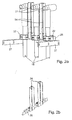
- FIG. 2a shows a perspective section of the cable connection space of the panel FIG. 1 with three electrical cables
- FIG. 2b shows a perspective view of the two arc stabilizers for attachment between the three electrical cables of FIG. 2a
- FIG. 3 shows a perspective section of the cable connection space of the panel FIG. 1 with nine electrical cables
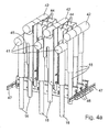
- FIG. 4a shows a perspective section of the cable connection space of the panel FIG. 1 with eighteen electrical cables
- FIG. 4b shows a perspective view of the twelve arc stabilizers for mounting between the eighteen electrical cables of FIG. 4a
- An electrical switchgear in particular a medium-voltage switchgear, consists of a plurality of switching fields.
- the panels are electrically connected to each other via busbars.
- different electrical components are housed, such as circuit breakers, disconnector / earthing switch and the like.
- branches from the busbars to electrical consumers are realized via these electrical components.
- FIG. 1 a single panel 10 is shown having a cabinet-shaped metallic housing 11.
- the housing 11 is grounded in a manner not shown.
- a cable connection space 17 is provided, via which the outlet to the mentioned electrical consumers is realized. This departure is carried out by means of electrical cables 18, which are led out through the cable connection space 17 down from the panel 10.
- each of the three cables 18 belongs to a phase of a three-phase electrical power supply.
- the three cables 18 extend within the cable connection space 17 approximately in the vertical direction from top to bottom.
- plug contacts 21 are provided in the upper Area of the cable connection space 17 are arranged stationary.
- the three plug contacts 21 of the cable 18 are aligned approximately in the horizontal direction.
- cable clamps 22 are provided with which the cables 18 are held stationary within the cable connection space 17.
- each two of the three cables 18 each have an arc stabilizer 24 is present.
- the two arc stabilizers 24 are thus always located between different phases of the three-phase electrical power supply.
- the local distance of each of the arc stabilizers 24 from the adjacent cables 18 is smaller than the local distance of the cable 18 from the housing 11 of the panel 10th
- the arc stabilizers 24 are elongate metal parts with an approximately U-shaped cross section.
- the arc stabilizers 24 are arranged with their longitudinal direction approximately parallel between each two cables 18.
- a first arc stabilizer 24 is disposed between the one outer and the middle cables 18 and a second arc stabilizer 24 between the other outer and the middle cables 18. Since the cables 18 are aligned approximately vertically within the cable connection space 17, and the arc stabilizers 24 are aligned approximately in the vertical direction.
- each of the three cables 18 at least always one leg of the U-shaped cross section of one of the two arc stabilizers 24 faces.
- the arc stabilizers 24 are present in a region in which the cables 18 extend approximately rectilinearly within the cable connection space 17.
- the length of the arc stabilizers 24 is smaller than the area in which the cables 18 extend approximately rectilinearly.
- the two arc stabilizers 24 are fixedly attached to a metal support 26.
- the metal carrier 26 is according to the FIG. 2a behind the cables 18 and extends approximately in the horizontal direction and thus transverse to the cables 18.
- At its two ends of the metal support 26 is fixed in each case fixed to a metallic support 27, which in turn, in a manner not shown on the housing 11 of the panel 10th are attached.
- FIG. 2b the two arc stabilizers 24 are shown without the cables 18. From the FIG. 2b goes the already mentioned U-shaped configuration of the arc stabilizers 24, and their approximately parallel alignment with each other. Furthermore, it can be seen how the two arc stabilizers 24 are held on the metal carrier 26.
- nine cables 18 are shown, which are housed in the cable connection space 17 and led out down from the panel 10.
- the nine cables 18 are composed of three groups, each with three cables 18, wherein the three cables 18 of a group belong to the three phases of an electrical power supply and thus each group seen in the embodiment of the FIG. 2a equivalent.
- the three groups, each with three cables 18 are according to the FIG. 3 arranged one behind the other within the cable connection space 17.
- the successively arranged cable 18 one and the same phase are connected to each other via a common plug contact 31.
- the nine cables 18 are thus connected to the other electrical components of the panel 10.
- the cables 18 by means of cable clamps 32 are held stationary within the cable connection space 17.
- arc stabilizer 24 present between each two of the three cables 18 of a group of cables 18 is in each case already on the basis of FIGS. 2a, 2b explained arc stabilizer 24 present.
- the one to one Group associated two arc stabilizers 24 are thus always located between different phases of the three-phase electrical power supply.
- the two arc stabilizers 24 are arranged in the same way between the cables 18 of a group and secured by means of the metal support 26 fixed, as for the three cables 18 of the FIGS. 2a, 2b has already been explained.
- each three arc stabilizers 24 are arranged one behind the other within the cable connection space 17.
- the metal carrier 26 are arranged one behind the other, in order to then be fixed on the housing 11 via the brackets 27.
- FIG. 4a eighteen cables 18 are shown, which are housed in the cable connection space 17 and led out of the panel 10 down.
- the eighteen cables 18 are composed of two arrays of three groups each, each group having three cables 18, and the three cables 18 of a group belonging to the three phases of electrical power supply.
- Each of the two arrangements of three groups of cables 18 corresponds to that in the FIG. 3 In each of the two arrangements, therefore, the three associated groups of cables 18 are arranged one behind the other in the cable connection space 17.
- the individual cables 18 of the two arrangements are arranged offset to one another, with regard to the cable connection space 17 in the horizontal and in the vertical direction.
- the cables 18 of the two arrangements are thus laterally offset from one another and the cables 18 of the one arrangement are arranged offset upwards in comparison to the cables 18 of the other arrangement.
- the cables 18 arranged one behind the other in one and the same phase of the two arrangements of cables 18 are connected to one another via a respective common plug contact 41, 42.
- the eighteen cables 18 are thus connected to the other electrical components of the panel 10.
- the cables 18 are held stationary within the cable connection space 17 by means of cable clamps (not shown).
- each two of the three cables 18 of a group of cables 18 arc stabilizers 44 are present.
- two arc stabilizers 44 belong to a group of three cables 18.
- the two arc stabilizers 44 belonging to a group are therefore always located between different phases of the three-phase electrical power supply.
- the local distance of each of the arc stabilizers 44 from the adjacent cables 18 is smaller than the local distance of the cable 18 from the housing 11 of the panel 10th
- the four arc stabilizers 44 of two laterally and upwardly offset groups of cables 18 of the two arrangements are designed as a common metallic arc stabilizer package 45.
- the six groups of cables 18 of the two arrangements there are thus three arc stabilizer packages 45.
- the three arc stabilizer packages 45 are housed one behind the other in the cable connection space 17.
- Each of the arc stabilizer packages 45 is quadruple U-shaped with the first and third U-shapes in the same direction while the second and fourth U-shapes are oriented in the opposite direction, and with the legs of adjacent U-shapes intertwined pass.
- the first and the third U-shape in each case provide arc stabilizers 44 between the cables 18 one group of one arrangement, while the second and fourth U-forms each represent arc stabilizers 44 between the cables of a group of the other arrangement.
- Each arc stabilizer package 45 thus contains four arc stabilizers 44 for two groups of cables 18.
- Each of the arc stabilizer packages 45 is fixedly attached to a metal support 46.
- the three metal supports 46 are arranged one behind the other within the cable connection space 17 and aligned approximately in the horizontal direction and thus approximately transversely to the cables 18. At their two ends, the three metal supports 46 are each held in a stationary manner on metallic holders 47, which in turn are fastened to the housing 11 of the cubicle 10.
- the three arc stabilizer packages 45 are shown with the four arc stabilizers 44, but without the cables 18. From the FIG. 4b goes the already mentioned four-fold U-shaped configuration of the LichtbogenstabilisatorVole 45, and their approximately parallel alignment with each other. It can also be seen how the two arc stabilizer packages 45 are held on the metal supports 46 and attached to the supports 47.
- the described electrical switchgear can be used not only in the field of medium voltage technology, but also in the low or high voltage technology. Furthermore, it is understood that the explained Cable connection space of the electrical switchgear can be located not only in the lower part of a panel, but also in other areas of the same. It should also be noted that not only plug contacts for connection to other electrical components can be provided, but also screw or clamp contacts or the like.
Landscapes
- Engineering & Computer Science (AREA)
- Power Engineering (AREA)
- Patch Boards (AREA)
Claims (6)
- Installation de distribution électrique, en particulier installation de distribution moyenne tension, comprenant un panneau de couplage (10) qui présente un boîtier métallique (11) dans lequel sont logés des composants électriques, et qui présente un compartiment de raccordement de câbles (17) dans lequel existent des câbles électriques (18), lesdits câbles (18) étant associés aux phases d'une alimentation en énergie électrique, entre deux câbles (18) de phase différente existant un stabilisateur d'arc électrique (24, 44), ledit stabilisateur d'arc électrique (24, 44) étant disposé dans une zone dans laquelle s'étendent les câbles (18) associés à l'intérieur dudit compartiment de raccordement de câbles (17), le stabilisateur d'arc électrique (24, 44) étant réalisé en métal, et caractérisée par le fait que ledit stabilisateur d'arc électrique est fixé à poste fixe dans ledit boîtier (11), que ledit stabilisateur d'arc électrique (24, 44) présente une section transversale à peu près en U et qu'une branche de la section transversale en U du stabilisateur d'arc électrique (24, 44) est tournée vers chacun des deux câbles (18).
- Installation de distribution électrique selon la revendication 1, dans laquelle ledit stabilisateur d'arc électrique (24, 44) est réalisé de manière oblongue et est disposé dans une zone dans laquelle les câbles (18) associés s'étendent de façon à peu près rectiligne à l'intérieur du compartiment de raccordement de câbles (17).
- Installation de distribution électrique selon l'une quelconque des revendications précédentes, dans laquelle, dans le cas d'une alimentation en énergie électrique triphasée, deux stabilisateurs d'arc électrique (24, 44) sont présents entre trois câbles (18), et dans laquelle les deux stabilisateurs d'arc électrique (24, 44) sont maintenus à poste fixe sur un support de métal (26, 46) qui est fixé à poste fixe sur ledit boîtier (11).
- Installation de distribution électrique selon la revendication 3, dans laquelle plusieurs groupes ayant chacun trois câbles (18) sont disposés les uns derrière les autres dans ledit compartiment de raccordement de câbles (17), et dans laquelle deux stabilisateurs d'arc électrique (24, 44) sont associés à chaque groupe.
- Installation de distribution électrique selon la revendication 4, dans laquelle les groupes de câbles (18) forment deux ensembles, les câbles (18) des deux ensembles étant disposés de manière à être décalés les uns par rapport aux autres à l'intérieur du compartiment de raccordement de câbles (17), et dans laquelle quatre stabilisateurs d'arc électrique (44) qui font partie de deux groupes d'ensembles différents forment un paquet commun de stabilisateurs d'arc électrique (45).
- Installation de distribution électrique selon la revendication 5, dans laquelle ledit paquet de stabilisateurs d'arc électrique (45) est réalisé quatre fois en U, les première et troisième formes en U présentant la même direction, tandis que les deuxième et quatrième formes en U sont orientées dans le sens opposé.
Applications Claiming Priority (1)
| Application Number | Priority Date | Filing Date | Title |
|---|---|---|---|
| DE200910032539 DE102009032539A1 (de) | 2009-07-10 | 2009-07-10 | Elektrische Schaltanlage, insbesondere Mittelspannungsschaltanlage |
Publications (2)
| Publication Number | Publication Date |
|---|---|
| EP2273634A1 EP2273634A1 (fr) | 2011-01-12 |
| EP2273634B1 true EP2273634B1 (fr) | 2014-09-17 |
Family
ID=42470613
Family Applications (1)
| Application Number | Title | Priority Date | Filing Date |
|---|---|---|---|
| EP20100161964 Active EP2273634B1 (fr) | 2009-07-10 | 2010-05-05 | Installation de commutation électrique, notamment installation de commutation moyenne tension |
Country Status (2)
| Country | Link |
|---|---|
| EP (1) | EP2273634B1 (fr) |
| DE (1) | DE102009032539A1 (fr) |
Cited By (1)
| Publication number | Priority date | Publication date | Assignee | Title |
|---|---|---|---|---|
| EP4379981A1 (fr) * | 2022-12-02 | 2024-06-05 | Schneider Electric Industries Sas | Ensemble d'extinction d'arc de compartiment de barre omnibus et armoire électrique |
Families Citing this family (3)
| Publication number | Priority date | Publication date | Assignee | Title |
|---|---|---|---|---|
| DE102011085099B4 (de) | 2011-10-24 | 2019-10-31 | Schneider Electric Sachsenwerk Gmbh | Elektrische Schaltanlage, insbesondere Mittelspannungsschaltanlage |
| US20240429689A1 (en) | 2021-05-18 | 2024-12-26 | Abb Schweiz Ag | Switchgear |
| EP4362249A1 (fr) * | 2022-10-27 | 2024-05-01 | Abb Schweiz Ag | Connecteur moyenne tension |
Family Cites Families (5)
| Publication number | Priority date | Publication date | Assignee | Title |
|---|---|---|---|---|
| DD99486A1 (fr) * | 1972-10-10 | 1973-08-13 | ||
| DE2817417A1 (de) * | 1978-04-18 | 1979-10-25 | Krone Gmbh | Gas- oder fluessigkeitsisolierte mittelspannungs-schaltanlage, insbesondere fuer spannungen von 1 bis 36 kv |
| DE69431270T2 (de) * | 1993-05-12 | 2003-05-08 | Kabushiki Kaisha Toshiba, Kawasaki | Leitender Verbinder für Schaltanlage |
| DE102004053613B4 (de) * | 2004-11-02 | 2006-09-28 | Siemens Ag | Schaltanlage mit einer entriegelnden Lichtbogenbegrenzung |
| ES2322828B2 (es) * | 2006-09-21 | 2010-04-07 | Ormazabal Distribucion Primaria, S.A. | Aparamenta modular de distribucion electrica. |
-
2009
- 2009-07-10 DE DE200910032539 patent/DE102009032539A1/de not_active Withdrawn
-
2010
- 2010-05-05 EP EP20100161964 patent/EP2273634B1/fr active Active
Cited By (1)
| Publication number | Priority date | Publication date | Assignee | Title |
|---|---|---|---|---|
| EP4379981A1 (fr) * | 2022-12-02 | 2024-06-05 | Schneider Electric Industries Sas | Ensemble d'extinction d'arc de compartiment de barre omnibus et armoire électrique |
Also Published As
| Publication number | Publication date |
|---|---|
| EP2273634A1 (fr) | 2011-01-12 |
| DE102009032539A1 (de) | 2011-01-13 |
Similar Documents
| Publication | Publication Date | Title |
|---|---|---|
| EP0872931B1 (fr) | Appareil de commutation électrique blindé à isolation gazeuse | |
| WO2005083859A1 (fr) | Installation de commutation a isolation gazeuse dans une enveloppe | |
| DE102007047200A1 (de) | Hochspannungsschaltanlage | |
| EP2572416B1 (fr) | Installation de commutation à isolation gazeuse | |
| EP2526597B1 (fr) | Module d'encapsulage avec des sectionneurs destine a un equipement electrique | |
| EP1277258B1 (fr) | Connecteur pour barres omnibus | |
| EP2273634B1 (fr) | Installation de commutation électrique, notamment installation de commutation moyenne tension | |
| DE19805705A1 (de) | Gasisolierte metallgekapselte Schaltanlage | |
| EP1249910A2 (fr) | Disjoncteur haute-tension pour une installation de commutation à isolation gaseuse | |
| WO2010133692A1 (fr) | Module isolé par gaz pour installation de commutation | |
| EP1927173B1 (fr) | Ensemble barre collectrice pour une installation de distribution electrique a double face de commande | |
| EP1728310A1 (fr) | Stator long comportant une ligne de terre et train a sustentation magnetique equipe de ce stator | |
| DE29706564U1 (de) | Trageinrichtung für Stromschienen | |
| EP2008348B1 (fr) | Equipement de commutation a moyenne tension a isolation par air | |
| EP2273525B1 (fr) | Commutateur de puissance électrique | |
| EP1927170B1 (fr) | Ensemble barre collectrice pour une installation de distribution electrique | |
| DE2800317A1 (de) | Gasisolierte schaltgeraetanlage | |
| EP1619766B1 (fr) | Dispositif de barres omnibus pour une armoire électrique basse tension | |
| DE102010050654B4 (de) | Anordnung von Leitern zum Anschluss eines Leistungsschalters | |
| EP2587599A1 (fr) | Appareillage électrique, en particulier appareillage électrique moyenne tension | |
| WO2008012012A1 (fr) | Module de barre collectrice pour une installation de distribution à haute tension isolée par gaz | |
| DE102010004971A1 (de) | Vorrichtung für eine Schaltanlage | |
| EP2016603B1 (fr) | Disjoncteur de puissance, en particulier disjoncteur de courant à haute intensité | |
| DE102009018170A1 (de) | Mehrphasige Schaltgeräteanordnung | |
| DE4426698B4 (de) | Metallgekapseltes, druckgasisoliertes Hochspannungsschaltgerät |
Legal Events
| Date | Code | Title | Description |
|---|---|---|---|
| PUAI | Public reference made under article 153(3) epc to a published international application that has entered the european phase |
Free format text: ORIGINAL CODE: 0009012 |
|
| AK | Designated contracting states |
Kind code of ref document: A1 Designated state(s): AL AT BE BG CH CY CZ DE DK EE ES FI FR GB GR HR HU IE IS IT LI LT LU LV MC MK MT NL NO PL PT RO SE SI SK SM TR |
|
| AX | Request for extension of the european patent |
Extension state: BA ME RS |
|
| 17P | Request for examination filed |
Effective date: 20110304 |
|
| GRAJ | Information related to disapproval of communication of intention to grant by the applicant or resumption of examination proceedings by the epo deleted |
Free format text: ORIGINAL CODE: EPIDOSDIGR1 |
|
| GRAP | Despatch of communication of intention to grant a patent |
Free format text: ORIGINAL CODE: EPIDOSNIGR1 |
|
| GRAP | Despatch of communication of intention to grant a patent |
Free format text: ORIGINAL CODE: EPIDOSNIGR1 |
|
| RIC1 | Information provided on ipc code assigned before grant |
Ipc: H02B 13/025 20060101ALN20140318BHEP Ipc: H02B 13/035 20060101ALN20140318BHEP Ipc: H01H 9/30 20060101ALN20140318BHEP Ipc: H02B 13/065 20060101AFI20140318BHEP |
|
| INTG | Intention to grant announced |
Effective date: 20140401 |
|
| INTG | Intention to grant announced |
Effective date: 20140409 |
|
| GRAS | Grant fee paid |
Free format text: ORIGINAL CODE: EPIDOSNIGR3 |
|
| GRAA | (expected) grant |
Free format text: ORIGINAL CODE: 0009210 |
|
| RAP1 | Party data changed (applicant data changed or rights of an application transferred) |
Owner name: SCHNEIDER ELECTRIC SACHSENWERK GMBH |
|
| AK | Designated contracting states |
Kind code of ref document: B1 Designated state(s): AL AT BE BG CH CY CZ DE DK EE ES FI FR GB GR HR HU IE IS IT LI LT LU LV MC MK MT NL NO PL PT RO SE SI SK SM TR |
|
| REG | Reference to a national code |
Ref country code: GB Ref legal event code: FG4D Free format text: NOT ENGLISH |
|
| REG | Reference to a national code |
Ref country code: CH Ref legal event code: EP |
|
| REG | Reference to a national code |
Ref country code: IE Ref legal event code: FG4D Free format text: LANGUAGE OF EP DOCUMENT: GERMAN |
|
| REG | Reference to a national code |
Ref country code: AT Ref legal event code: REF Ref document number: 688069 Country of ref document: AT Kind code of ref document: T Effective date: 20141015 |
|
| REG | Reference to a national code |
Ref country code: DE Ref legal event code: R096 Ref document number: 502010007900 Country of ref document: DE Effective date: 20141030 |
|
| PG25 | Lapsed in a contracting state [announced via postgrant information from national office to epo] |
Ref country code: SE Free format text: LAPSE BECAUSE OF FAILURE TO SUBMIT A TRANSLATION OF THE DESCRIPTION OR TO PAY THE FEE WITHIN THE PRESCRIBED TIME-LIMIT Effective date: 20140917 Ref country code: GR Free format text: LAPSE BECAUSE OF FAILURE TO SUBMIT A TRANSLATION OF THE DESCRIPTION OR TO PAY THE FEE WITHIN THE PRESCRIBED TIME-LIMIT Effective date: 20141218 Ref country code: FI Free format text: LAPSE BECAUSE OF FAILURE TO SUBMIT A TRANSLATION OF THE DESCRIPTION OR TO PAY THE FEE WITHIN THE PRESCRIBED TIME-LIMIT Effective date: 20140917 Ref country code: LT Free format text: LAPSE BECAUSE OF FAILURE TO SUBMIT A TRANSLATION OF THE DESCRIPTION OR TO PAY THE FEE WITHIN THE PRESCRIBED TIME-LIMIT Effective date: 20140917 Ref country code: NO Free format text: LAPSE BECAUSE OF FAILURE TO SUBMIT A TRANSLATION OF THE DESCRIPTION OR TO PAY THE FEE WITHIN THE PRESCRIBED TIME-LIMIT Effective date: 20141217 |
|
| REG | Reference to a national code |
Ref country code: NL Ref legal event code: VDEP Effective date: 20140917 |
|
| REG | Reference to a national code |
Ref country code: LT Ref legal event code: MG4D |
|
| PG25 | Lapsed in a contracting state [announced via postgrant information from national office to epo] |
Ref country code: CY Free format text: LAPSE BECAUSE OF FAILURE TO SUBMIT A TRANSLATION OF THE DESCRIPTION OR TO PAY THE FEE WITHIN THE PRESCRIBED TIME-LIMIT Effective date: 20140917 Ref country code: HR Free format text: LAPSE BECAUSE OF FAILURE TO SUBMIT A TRANSLATION OF THE DESCRIPTION OR TO PAY THE FEE WITHIN THE PRESCRIBED TIME-LIMIT Effective date: 20140917 Ref country code: LV Free format text: LAPSE BECAUSE OF FAILURE TO SUBMIT A TRANSLATION OF THE DESCRIPTION OR TO PAY THE FEE WITHIN THE PRESCRIBED TIME-LIMIT Effective date: 20140917 |
|
| PG25 | Lapsed in a contracting state [announced via postgrant information from national office to epo] |
Ref country code: NL Free format text: LAPSE BECAUSE OF FAILURE TO SUBMIT A TRANSLATION OF THE DESCRIPTION OR TO PAY THE FEE WITHIN THE PRESCRIBED TIME-LIMIT Effective date: 20140917 |
|
| PG25 | Lapsed in a contracting state [announced via postgrant information from national office to epo] |
Ref country code: CZ Free format text: LAPSE BECAUSE OF FAILURE TO SUBMIT A TRANSLATION OF THE DESCRIPTION OR TO PAY THE FEE WITHIN THE PRESCRIBED TIME-LIMIT Effective date: 20140917 Ref country code: ES Free format text: LAPSE BECAUSE OF FAILURE TO SUBMIT A TRANSLATION OF THE DESCRIPTION OR TO PAY THE FEE WITHIN THE PRESCRIBED TIME-LIMIT Effective date: 20140917 Ref country code: IS Free format text: LAPSE BECAUSE OF FAILURE TO SUBMIT A TRANSLATION OF THE DESCRIPTION OR TO PAY THE FEE WITHIN THE PRESCRIBED TIME-LIMIT Effective date: 20150117 Ref country code: PT Free format text: LAPSE BECAUSE OF FAILURE TO SUBMIT A TRANSLATION OF THE DESCRIPTION OR TO PAY THE FEE WITHIN THE PRESCRIBED TIME-LIMIT Effective date: 20150119 Ref country code: RO Free format text: LAPSE BECAUSE OF FAILURE TO SUBMIT A TRANSLATION OF THE DESCRIPTION OR TO PAY THE FEE WITHIN THE PRESCRIBED TIME-LIMIT Effective date: 20140917 Ref country code: SK Free format text: LAPSE BECAUSE OF FAILURE TO SUBMIT A TRANSLATION OF THE DESCRIPTION OR TO PAY THE FEE WITHIN THE PRESCRIBED TIME-LIMIT Effective date: 20140917 Ref country code: EE Free format text: LAPSE BECAUSE OF FAILURE TO SUBMIT A TRANSLATION OF THE DESCRIPTION OR TO PAY THE FEE WITHIN THE PRESCRIBED TIME-LIMIT Effective date: 20140917 |
|
| PG25 | Lapsed in a contracting state [announced via postgrant information from national office to epo] |
Ref country code: PL Free format text: LAPSE BECAUSE OF FAILURE TO SUBMIT A TRANSLATION OF THE DESCRIPTION OR TO PAY THE FEE WITHIN THE PRESCRIBED TIME-LIMIT Effective date: 20140917 |
|
| REG | Reference to a national code |
Ref country code: DE Ref legal event code: R097 Ref document number: 502010007900 Country of ref document: DE |
|
| PLBE | No opposition filed within time limit |
Free format text: ORIGINAL CODE: 0009261 |
|
| STAA | Information on the status of an ep patent application or granted ep patent |
Free format text: STATUS: NO OPPOSITION FILED WITHIN TIME LIMIT |
|
| PG25 | Lapsed in a contracting state [announced via postgrant information from national office to epo] |
Ref country code: DK Free format text: LAPSE BECAUSE OF FAILURE TO SUBMIT A TRANSLATION OF THE DESCRIPTION OR TO PAY THE FEE WITHIN THE PRESCRIBED TIME-LIMIT Effective date: 20140917 |
|
| 26N | No opposition filed |
Effective date: 20150618 |
|
| PG25 | Lapsed in a contracting state [announced via postgrant information from national office to epo] |
Ref country code: IT Free format text: LAPSE BECAUSE OF FAILURE TO SUBMIT A TRANSLATION OF THE DESCRIPTION OR TO PAY THE FEE WITHIN THE PRESCRIBED TIME-LIMIT Effective date: 20140917 |
|
| PG25 | Lapsed in a contracting state [announced via postgrant information from national office to epo] |
Ref country code: SI Free format text: LAPSE BECAUSE OF FAILURE TO SUBMIT A TRANSLATION OF THE DESCRIPTION OR TO PAY THE FEE WITHIN THE PRESCRIBED TIME-LIMIT Effective date: 20140917 |
|
| REG | Reference to a national code |
Ref country code: CH Ref legal event code: PL |
|
| GBPC | Gb: european patent ceased through non-payment of renewal fee |
Effective date: 20150505 |
|
| PG25 | Lapsed in a contracting state [announced via postgrant information from national office to epo] |
Ref country code: CH Free format text: LAPSE BECAUSE OF NON-PAYMENT OF DUE FEES Effective date: 20150531 Ref country code: LU Free format text: LAPSE BECAUSE OF FAILURE TO SUBMIT A TRANSLATION OF THE DESCRIPTION OR TO PAY THE FEE WITHIN THE PRESCRIBED TIME-LIMIT Effective date: 20150505 Ref country code: MC Free format text: LAPSE BECAUSE OF FAILURE TO SUBMIT A TRANSLATION OF THE DESCRIPTION OR TO PAY THE FEE WITHIN THE PRESCRIBED TIME-LIMIT Effective date: 20140917 Ref country code: LI Free format text: LAPSE BECAUSE OF NON-PAYMENT OF DUE FEES Effective date: 20150531 |
|
| REG | Reference to a national code |
Ref country code: IE Ref legal event code: MM4A |
|
| REG | Reference to a national code |
Ref country code: FR Ref legal event code: ST Effective date: 20160129 |
|
| PG25 | Lapsed in a contracting state [announced via postgrant information from national office to epo] |
Ref country code: GB Free format text: LAPSE BECAUSE OF NON-PAYMENT OF DUE FEES Effective date: 20150505 Ref country code: IE Free format text: LAPSE BECAUSE OF NON-PAYMENT OF DUE FEES Effective date: 20150505 |
|
| PG25 | Lapsed in a contracting state [announced via postgrant information from national office to epo] |
Ref country code: FR Free format text: LAPSE BECAUSE OF NON-PAYMENT OF DUE FEES Effective date: 20150601 |
|
| REG | Reference to a national code |
Ref country code: AT Ref legal event code: MM01 Ref document number: 688069 Country of ref document: AT Kind code of ref document: T Effective date: 20150505 |
|
| PG25 | Lapsed in a contracting state [announced via postgrant information from national office to epo] |
Ref country code: AT Free format text: LAPSE BECAUSE OF NON-PAYMENT OF DUE FEES Effective date: 20150505 |
|
| PG25 | Lapsed in a contracting state [announced via postgrant information from national office to epo] |
Ref country code: MT Free format text: LAPSE BECAUSE OF FAILURE TO SUBMIT A TRANSLATION OF THE DESCRIPTION OR TO PAY THE FEE WITHIN THE PRESCRIBED TIME-LIMIT Effective date: 20140917 |
|
| PG25 | Lapsed in a contracting state [announced via postgrant information from national office to epo] |
Ref country code: SM Free format text: LAPSE BECAUSE OF FAILURE TO SUBMIT A TRANSLATION OF THE DESCRIPTION OR TO PAY THE FEE WITHIN THE PRESCRIBED TIME-LIMIT Effective date: 20140917 Ref country code: BG Free format text: LAPSE BECAUSE OF FAILURE TO SUBMIT A TRANSLATION OF THE DESCRIPTION OR TO PAY THE FEE WITHIN THE PRESCRIBED TIME-LIMIT Effective date: 20140917 Ref country code: HU Free format text: LAPSE BECAUSE OF FAILURE TO SUBMIT A TRANSLATION OF THE DESCRIPTION OR TO PAY THE FEE WITHIN THE PRESCRIBED TIME-LIMIT; INVALID AB INITIO Effective date: 20100505 |
|
| PG25 | Lapsed in a contracting state [announced via postgrant information from national office to epo] |
Ref country code: BE Free format text: LAPSE BECAUSE OF NON-PAYMENT OF DUE FEES Effective date: 20150531 |
|
| PG25 | Lapsed in a contracting state [announced via postgrant information from national office to epo] |
Ref country code: TR Free format text: LAPSE BECAUSE OF FAILURE TO SUBMIT A TRANSLATION OF THE DESCRIPTION OR TO PAY THE FEE WITHIN THE PRESCRIBED TIME-LIMIT Effective date: 20140917 |
|
| PG25 | Lapsed in a contracting state [announced via postgrant information from national office to epo] |
Ref country code: MK Free format text: LAPSE BECAUSE OF FAILURE TO SUBMIT A TRANSLATION OF THE DESCRIPTION OR TO PAY THE FEE WITHIN THE PRESCRIBED TIME-LIMIT Effective date: 20140917 |
|
| PG25 | Lapsed in a contracting state [announced via postgrant information from national office to epo] |
Ref country code: AL Free format text: LAPSE BECAUSE OF FAILURE TO SUBMIT A TRANSLATION OF THE DESCRIPTION OR TO PAY THE FEE WITHIN THE PRESCRIBED TIME-LIMIT Effective date: 20140917 |
|
| REG | Reference to a national code |
Ref country code: DE Ref legal event code: R084 Ref document number: 502010007900 Country of ref document: DE |
|
| PGFP | Annual fee paid to national office [announced via postgrant information from national office to epo] |
Ref country code: DE Payment date: 20250402 Year of fee payment: 16 |