EP2273635A2 - Réseau modulaire pour la distribution et le contrôle de la puissance électrique - Google Patents
Réseau modulaire pour la distribution et le contrôle de la puissance électrique Download PDFInfo
- Publication number
- EP2273635A2 EP2273635A2 EP10251145A EP10251145A EP2273635A2 EP 2273635 A2 EP2273635 A2 EP 2273635A2 EP 10251145 A EP10251145 A EP 10251145A EP 10251145 A EP10251145 A EP 10251145A EP 2273635 A2 EP2273635 A2 EP 2273635A2
- Authority
- EP
- European Patent Office
- Prior art keywords
- type
- socket
- plug
- sockets
- operably
- Prior art date
- Legal status (The legal status is an assumption and is not a legal conclusion. Google has not performed a legal analysis and makes no representation as to the accuracy of the status listed.)
- Withdrawn
Links
- 230000037361 pathway Effects 0.000 claims abstract description 71
- 230000007613 environmental effect Effects 0.000 claims abstract description 4
- 230000007935 neutral effect Effects 0.000 claims description 25
- 239000004020 conductor Substances 0.000 claims description 13
- 238000000034 method Methods 0.000 claims description 12
- 230000001681 protective effect Effects 0.000 claims description 3
- 238000010348 incorporation Methods 0.000 abstract description 2
- 238000009434 installation Methods 0.000 description 5
- 238000003491 array Methods 0.000 description 4
- 238000000926 separation method Methods 0.000 description 3
- 241000239290 Araneae Species 0.000 description 2
- 230000008901 benefit Effects 0.000 description 2
- 238000010586 diagram Methods 0.000 description 2
- 239000012777 electrically insulating material Substances 0.000 description 2
- 230000006870 function Effects 0.000 description 2
- 238000012986 modification Methods 0.000 description 2
- 230000004048 modification Effects 0.000 description 2
- 238000012360 testing method Methods 0.000 description 2
- 241001465754 Metazoa Species 0.000 description 1
- 241000220317 Rosa Species 0.000 description 1
- 238000004891 communication Methods 0.000 description 1
- 230000001419 dependent effect Effects 0.000 description 1
- 230000000694 effects Effects 0.000 description 1
- 230000008030 elimination Effects 0.000 description 1
- 238000003379 elimination reaction Methods 0.000 description 1
- 230000013011 mating Effects 0.000 description 1
- 230000007246 mechanism Effects 0.000 description 1
- 239000002243 precursor Substances 0.000 description 1
- 230000009467 reduction Effects 0.000 description 1
Images



Classifications
-
- H—ELECTRICITY
- H02—GENERATION; CONVERSION OR DISTRIBUTION OF ELECTRIC POWER
- H02G—INSTALLATION OF ELECTRIC CABLES OR LINES, OR OF COMBINED OPTICAL AND ELECTRIC CABLES OR LINES
- H02G3/00—Installations of electric cables or lines or protective tubing therefor in or on buildings, equivalent structures or vehicles
-
- H—ELECTRICITY
- H02—GENERATION; CONVERSION OR DISTRIBUTION OF ELECTRIC POWER
- H02G—INSTALLATION OF ELECTRIC CABLES OR LINES, OR OF COMBINED OPTICAL AND ELECTRIC CABLES OR LINES
- H02G3/00—Installations of electric cables or lines or protective tubing therefor in or on buildings, equivalent structures or vehicles
- H02G3/02—Details
-
- H—ELECTRICITY
- H02—GENERATION; CONVERSION OR DISTRIBUTION OF ELECTRIC POWER
- H02G—INSTALLATION OF ELECTRIC CABLES OR LINES, OR OF COMBINED OPTICAL AND ELECTRIC CABLES OR LINES
- H02G3/00—Installations of electric cables or lines or protective tubing therefor in or on buildings, equivalent structures or vehicles
- H02G3/02—Details
- H02G3/08—Distribution boxes; Connection or junction boxes
Definitions
- the invention relates to a modular network for distributing electrical power in a structure, such as a building, to power outlet sockets, luminaires, control switches and the like.
- the invention relates to a modular network which may be customised to a particular structure, such as a building having various interior rooms, corridors etc., by plugging together modules, such as prefabricated or pre-wired modules, using connection cables in order to achieve a power distribution network.
- the invention is also suitable for a network that, in addition to distributing electrical power, enables control and switching of outlet sockets and/or luminaires.
- Typical buildings are provided with networks of electrical power outlet sockets and lighting systems which are interconnected, via a wiring network and control switches, to a mains power supply. This is the case for both residential buildings and larger non-residential buildings.
- cables are connected from a central distribution board, which distributes the single phase mains supply, directly to outlet sockets, switches and luminaires. Containment of cables is typically within conduit or trunking extending through the structure.
- the wiring of switches, cables luminaires is typically achieved using hard-wired screw connectors. Cables are cut to length and hard-wired to the luminaires or switches.
- luminaires are linked into a hard wired system using plug and socket connection interfaces.
- the sockets form part of the fixed wiring with the plug connected to the luminaire fitting by a cable to allow simple connection and disconnection of luminaires into the power supply network.
- the plug may be pre-wired into order to reduce installation time.
- a spider distribution method involves the use of marshalling boxes.
- the marshalling boxes are used to distribute and control power to a number of luminaire fittings. Control may be integrated by the use of an occupancy sensor, for instance, to provide localised automatic switching of all luminaires attached to a particular marshalling box.
- Marshalling boxes have typically a single incoming hardwired connection and the electrical and are a cost effect method for installations of large numbers of luminaires. Rather than the luminaires being hard-wired to the marshalling box and control system, the luminaires may be connected to the marshalling box via a plug and socket connection at each luminaire.
- Digital lighting control systems are also known in the prior art. Such systems distribute both power and data signals to digital controllers arranged to control the power supply to luminaires. Such systems offer benefits of increases levels of control and potential for energy saving. For instance, digital occupancy sensors may be used to detect when rooms are empty and switch off the lights in order to save energy. Ambient lighting detectors may also be used to switch off lights when there is sufficient ambient lighting that electrical lighting is unnecessary. Over-ride mechanisms may be provided. Digital communication protocols such as DALI or DSI are used to control the individual systems. DALI is Digital Addressable Lighting Interface as set out in IEC62386. DSI is Digital Signal Interface and was the precursor for the DALI system.
- control systems and power distribution systems are dealt with as separate but interconnected systems by installers.
- a first aspect of the invention provides a modular network for providing power, lighting and control circuits for a location in a structure, wherein the modular network comprises a plurality of conductive pathways operably distributed to a plurality of power outlet sockets and/or luminaires and/or switching means and/or power control means, wherein the modular network comprises:
- a second aspect of the invention provides a power and lighting array comprising a plurality of modular networks according to the first aspect of the invention, for providing power, lighting and control circuits for a plurality of locations in a structure and central distribution unit operably connected to a mains three pole and neutral power supply, wherein the single phase power supplies for each modular network are provided by the central distribution unit.
- a third aspect of the invention provides a method for supplying power, lighting and control circuits for a structure, comprising providing one or more modular networks according to the first aspect of the invention, or a power and lighting array according to the second aspect of the invention, in the structure.
- the structure will be a building.
- a fourth aspect of the invention provides a connection cable for use in a modular network according to the first aspect of the invention comprising:
- a fifth aspect of the invention provides a marshalling module for use in a modular network according to any one of claims 1 to 13 comprising:
- a sixth aspect of the invention provides a kit of parts for interconnecting to form a modular network according to the first aspect of the invention, wherein the kit comprises:
- the first aspect of the invention provides a modular network having a plurality of conductive pathways.
- the modular network has seven or more conductive pathways.
- the conductive pathways will comprise a pair of conductors connected to a single phase supply (phase and neutral - commonly referred to as “live” or “phase live” and “neutral” or “neutral live”), a circuit protective conductor(earth), a switched live conductor(switched-live), an emergency switched-live conductor(emergency switched-live), a first control conductor(D+) and a second control conductor(D-).
- the modular network will be arranged to provide at least one of a power outlet socket circuit, a switched lighting circuit, an emergency lighting circuit and an environmental lighting control circuit for a structure or part thereof. It may be configured to provide all or some of these circuits.
- the modular network preferably has at least seven conductive pathways, and will typically only have seven conductive pathways, it should be noted that in any particular network configuration, not all of the pathways might be conductively connected to form circuits. For instance, when the modules of the network are used solely to provide power outlet sockets, it may be that only the phase live, neutral and earth pathways need to be conductively connected within the modular network.
- a benefit of the invention over the prior art is its versatility for use in provision of multiple circuits by means of interconnection of modular components with reduction in, or elimination of, the need for hard-wiring.
- the term "operably connected" in this specification is to be taken to mean “at least partially conductively connected”.
- modules of the network When the modules of the network are used to provide power outlet sockets and manually switched luminaires, it may be that only the live (phase), neutral, earth and switched live pathways are operably connected within the modular network, or within a relevant part of the modular network, with switch modules connected into the network and switching between phase and switched-live conductive pathways to control the luminaires.
- the modules of the network are used to provide power outlet sockets and manually switched luminaires as well as emergency luminaires (which are arranged to illuminate when an emergency condition is activated, such as a loss of main circuit power), for instance illuminating emergency exit routes, then it may be that only the phase live , neutral, earth emergency switched live and switched live pathways are operably connected within the modular network, or within a part of the modular network, with an emergency control switch connected into the network and switching between phase live and emergency switched-live conductive pathways to control the emergency luminaires.
- emergency luminaires which are arranged to illuminate when an emergency condition is activated, such as a loss of main circuit power
- the modular network of the invention has two types of plug and socket arrangements for interconnection of the components of the modular network, type-one and type-two.
- these power outlet sockets would be conventional power outlet sockets, such as three-pin sockets according to the local national standards. For instance in the UK, the power outlet sockets will typically conform to British standard BS 1363.
- the power outlet sockets are not to be considered as either the type-one sockets or the type-two sockets.
- the type-one plug and socket arrangements and type-two plug and socket arrangements will be specific arrangements for use within the network and are not intended for manipulation by an end-user once the modular network has been installed.
- the interconnections of the modular network will be concealed from an end-user within conduits or behind walls or ceilings of the structure so that they are only accessible by electricians rather than accessible to the end-user.
- the type-one plug and socket arrangement and the type-two plug and socket arrangement may be any suitable arrangements, with the provisos that a type-one plug is arranged to operably engage with a type-one socket but not with a type-two socket and a type-two plug is arranged to operably engage with a type-two socket but not with a type-one socket.
- both the type-one and type-two sockets may each have seven connectors, whereas the type-one and type-two plugs may have three, five or seven connectors arranged to interconnect with the corresponding connectors of the type-one or type-two sockets when the plugs and sockets are interengaged.
- the incoming type-two plug may be a three-pin plug with the connectors arranged to provide these three circuits. If the D+ and D- control circuits are not needed for a luminaire, then, for instance it may be connected into the network at a type-one socket using a five-connector type-one plug, wherein the connectors are arranged to provide phase live , neutral, earth, switched live and emergency switched live circuits.
- the selection of a 3-, 5-, or 7-connector plug may be used to configure the circuit connections for the modular network of the invention.
- the plug and socket arrangements of the invention will be arranged to be lockable in an engaged (i.e. connected) configuration. This is because, once the modular network is in place, there will be little regular disconnection of the plug and socket arrangements of the network, and so a lockable engagement is preferred to prevent unintentional disconnection of modular components of the network.
- plug in this specification, there is no limitation intended concerning whether the connectors of the plug are male connectors or female connectors.
- the term "plug” is merely meant to convey that this is the part of a plug and socket arrangement that is moved to engage or disengage the plug and socket engagement whilst the socket part typically remains stationary or fixed.
- a plug will typically be located at an end of a connecting cable whereas a socket will be directly form part of a module of the network.
- the type-one and type-two plugs may differ from each other in that one is a male plug ,with male connectors projecting from a plug engagement face and the other is a female plug, with female connectors located in a plug face.
- the type-one plugs are male plugs and the type-two plugs are female plugs.
- the plug with male connectors the type-one plug
- the socket, with male connectors the type-two socket
- this configuration avoids male connectors (which are the connectors most likely to be accidentally or unintentionally contacted because they project from plug engagement face rather than being recessed into it) ever being live when exposed in a partially live modular network.
- the female connectors are the only connectors that may be exposed in a live state for this preferred configuration, and so are less likely to be accidentally contacted, particularly by a part of a human or animal body, provided that the female openings of the connectors are sufficiently small in aperture to prevent the ingress of body parts such as fingers.
- the plug and socket arrangements may suitably comprise a plug and a socket having an unengaged configuration wherein the plug and socket are physically separated and electrically unconnected, and an engaged configuration wherein the plug and socket are electrically connected and mechanically interlocked.
- the plug may have a plug engagement face comprising plurality of first, male or female, interlocking members adapted to mate with a plurality of second, female or male, interlocking members provided in a socket engagement face of the socket, wherein the first and second interlocking members are adapted to be brought into a first mated configuration with the plug and socket engagement faces substantially mutually parallel and brought together by a first relative movement of plug and socket along a first direction substantially normal to the engagement faces, and wherein the first and second interlocking members, when in the first mated configuration, are arranged to permit relative movement of the plug and socket into the engaged configuration along a second direction substantially parallel to the plug and socket engagement faces, and wherein the first and second interlocking members are arranged to interlock in a second mated configuration when the plug and socket are in the engaged configuration whereby separation of the engagement faces along the first direction is prevented.
- the male and female interlocking members may comprise conductive members whereby electrical connection is made, but preferably, each male interlocking member may comprise a pillar having pillar walls of electrically insulating material comprising a first electrical contact, and each female interlocking member may comprise a cavity having cavity walls of electrically insulating material comprising a second electrical contact, whereby the first and second electrical contacts are electrically isolated in the first mated configuration and electrically connected in the second mated configuration.
- the male interlocking members are adapted to shield the first electrical contact from accidental contact with a human body part when the plug and socket are in the unengaged configuration.
- the female interlocking members are adapted to shield the first electrical contact from accidental contact with a human body part when the plug and socket are in the unengaged configuration.
- the male interlocking members may comprise a first insulating arm extending in the first direction from the plug or socket to its distal end with a second insulating arm extending from the distal end of the first arm in the second direction, wherein the first electrical contact is located between the second arm and the engagement face of the plug.
- the female members may then suitably comprise a first shat extending in the first direction from the plug or socket face to a basal end, adapted to allow the first and second arms of the corresponding male interlocking member to enter the female interlocking member in the first direction to give the first mated configuration, and a second shaft, extending from the basal end in the second direction, adapted to allow the second arm to slide into the second shaft in the second direction to provide the second mated configuration, and wherein the second electrical contact is located between the second shaft and the engagement face of the plug or socket, whereby the first and second electrical contacts are brought into electrically conductive contact by the second movement.
- the plug and socket arrangements of the network further comprise a latching arrangement whereby the plug and socket arrangement, once in the engaged configuration, cannot be disengaged without first releasing the latching arrangement.
- This latching arrangement thus acts to prevent unintentional disengagement of a plug and socket arrangement.
- the plug and socket arrangement is as detailed hereinbefore, and is engaged by a first movement in a first direction substantially normal to the plug and socket engagement faces to bring the engagement faces together, mating the male and female interlocking members, followed by a second movement in a second direction substantially parallel to the plug and socket faces to mechanically engage the faces together to prevent separation in the first direction, whereby electrical connection is also made at the male and female interlocking members, then the latching arrangement is suitably configured to prevent movement back along the second direction unless the latching arrangement is unlatched.
- a suitable latching arrangement may comprise a male interlocking member of a component (plug or socket) comprising a latching means in the form of a detent or pawl, such as a rib or tooth, and a corresponding female interlocking member of a component (socket or plug) comprising a notch, such as a groove or recess, arranged to engage with the latching means.
- a male interlocking member of a component plug or socket
- a latching means in the form of a detent or pawl, such as a rib or tooth
- a corresponding female interlocking member of a component pluget or plug
- a notch such as a groove or recess
- Unlatching is achieved by pushing the engagement faces together, against the urging of the resilient means, whereby the gap is closed and the latching arrangement brought into an unlatched configuration, such that the plug and socket may be disengaged by mutual relative movement in the reverse of the second direction followed by separation in the reverse of the first direction.
- the plug is arranged to accept an electrical cable substantially oriented along the second direction, whereby a tensile force along the cable urges the plug towards the engaged configuration.
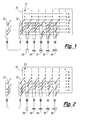
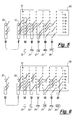
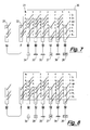
- the local distribution module of the modular network of the system is used to provide a plurality of circuits to a region of a structure.
- the interconnection, switching and control of the circuits will be dependent upon the termination modules connected directly, or through optional marshalling modules, to the local distribution module.
- a termination module of the modular network of the invention may be a power outlet socket, comprising either a type-one plug or a type-two socket, connected to the type-one sockets of the local distribution module either directly or indirectly via the connection cables and/or optional marshalling modules.
- the local distribution module may be used to provide circuits for a plurality of power outlet sockets for part of a structure, such as part of a building, all powered through the local distribution module. Typically, only phase live , neutral and earth circuits will be connected for these power outlet socket modules.
- a termination module of the network may be a luminaire comprising either a type-one plug or a type-two socket, connected to the type-one sockets of the local distribution module either directly or indirectly via the connection cables and/or optional marshalling modules.
- a luminaire will be arranged to have, as its main power supply, either the switched- live or emergency switched-live circuits.
- Luminaires for use in the modular network of the invention may also be provided with a digital controller, such as an electronic ballast, as part of the luminaire, such that signals to the luminaire's digital controller, sent using the D+ and D-conductive pathways, may be used to control the light output of the luminaire when it is switched on.
- the plug/socket arrangement used to connect the luminaire into the network can be suitably wired to provide the conductive pathways needed.
- a termination module of the modular network of the invention may be a switching means, comprising either a type-one plug or a type-two socket, connected to the type-one sockets of the local distribution module either directly or indirectly via the connection cables and/or optional marshalling modules. It is a particularly advantageous feature of the invention that the switching means may be used by connecting it to any suitable type-one socket, so for instance the same socket could be used for either a switch means or a luminaire.
- the switching means is suitably a conventional one-way on/off electrical power switch, and will typically be connected to make or break a connection between the phase live and switched-live conductive pathways connected through the switch.
- Such switches may be operably interconnected to one or more luminaires by operable connection of the switch module and the luminaires (directly or through a daisy-chain of further marshalling modules) to type-one sockets of the local distribution module of the network, such that when the switch makes or breaks the connection between live(phase) and switched-live circuits through the local distribution module, the luminaires connected through the local distribution module are switched on and off respectively.
- the luminaire power supply is arranged to be through the switched-live circuit from the local distribution module.
- a similar arrangement may be used for an emergency lighting circuit, where the switch is an emergency switch and is arranged to make or break a connection between the phase live and emergency switched-live conductive pathways connected through the emergency switch.
- Any luminaires operably connected to a local distribution module directly or through marshalling modules), where the local distribution module is also operably connected to the emergency switch, and with the power for the luminaires arranged to be supplied through the emergency switched-live circuit, will be switched on and off by the emergency switch.
- the emergency switch may be a manual switch, such as a circuit check switch, typically operated by a key to check correct functioning of an emergency lighting circuit, or may be a servo-controlled switch, for instance, operated by an alarm or power failure system of a structure.
- the emergency switched-live conductive pathway for the module may be connected to a central control system for the structure (such as an alarm system or building management system) so that in an emergency, the emergency switched live circuit would be made live from the central control system, perhaps using an alternative emergency power supply.
- a central control system for the structure such as an alarm system or building management system
- the local emergency circuit of the modular network can be tested using the emergency switch connected to the local distribution module, connecting the emergency live to the phase live for testing.
- a termination module of the network may be a power control means module comprising either a type-one plug or a type-two socket, connected to the type-one sockets of the local distribution module either directly or indirectly via the connection cables and/or optional marshalling modules.
- the power control means may thus be interconnected to the digital controllers of the luminaires of the network such that digital signals sent using the D+ and D+ circuits may be used to control the light output from the luminaires when they are switched on.
- a power control module may comprise an occupancy sensor, such as a movement detector, whereby the power control module may reduce or turn off the luminaires output when no movement is detected, thus saving energy when a space to be illuminated is left unoccupied. It is a particularly advantageous feature of the invention that the power control means may be used by connecting it to any suitable type-one socket, so for instance the same type-one socket could be used for either a power control means or for a luminaire.
- a power control module may comprise an ambient light sensor, whereby the power control module may reduce or turn off the luminaires output when ambient light in a space is adequate, thus saving energy when a space to be illuminated is already illuminated by ambient light.
- the modular network of the invention may comprise marshalling modules. These comprise a type-two socket for input of the conductive pathways and at least one type-one socket operably connected thereto for output of the conductive pathways to other modules of the network. Marshalling modules may be used to provide differing circuit arrangements from a local distribution module of the network of the invention.
- the operable connection between a type-one plug and a type-two plug in marshalling module or in a connection cable may have some of the conductive pathways being left unconnected.
- an operable engagement between a type-one plug and a type-one socket may have some of the conductive pathways being left unconnected.
- an operable engagement between a type-two plug and a type-two socket may have some of the conductive pathways being left unconnected.
- the type-one plugs may be colour-coded in order to indicate their function, such as what their safe current rating is and what modules they are suitable to connect.
- the type-two plugs may be colour coded in order to indicate their function.
- the colour coding may similarly indicate the connectivity of the plugs (i.e. which connectors are connectable through that plug).
- Marshalling modules of the network may also be colour coded in a similar manner.
- the modular network of the first aspect of the invention may comprise a marshalling module which is a two-way switch module, the two-way switch module comprising a type-two socket and two type-one sockets, wherein the type-two and type-one sockets are operably connected to provide a two-way switch when first and second switch modules are connected to each of the type-one sockets, whereby the first and second switches independently control the operation of luminaires operably connected to the type-two socket of the lighting control module.
- the switch modules are switch modules arranged to switch between the phase live and switched-live conductive pathways, and so are standard switch modules for use with the network of the invention. By suitable internal wiring of the lighting control module, for instance using the switched-live and D+ pathways within the lighting control module as strappers.
- marshalling modules may be envisaged, making use of specific interconnections between the type-one sockets and type-two socket of the marshalling module to provide specific circuit connectivity.
- the modular network of the invention may be arranged to provide several self-contained lighting control circuits as part of the modular network.
- the switched-live of the central marshalling module for each self-contained lighting circuit is not connected to the switched lives of the other self-contained lighting circuits through the local distribution module.
- This disconnection may be by use of connection cables from the local distribution module to the respective marshalling modules where the switched live is not connected in those cables.
- the cables may be suitably marked to show this to facilitate correct interconnection of the modular network (such as by colour-coding).
- the local distribution module is operably connected to a power supply as input, typically a single phase power supply, providing phase live , neutral and earth connections to the live(phase), neutral and earth conductive pathways of the modular network of the invention.
- a power supply as input typically a single phase power supply
- the other conductive pathways are not necessarily connected outside the modular network, and so can be used for self-contained control of lighting and emergency circuits within the modular network.
- the local distribution module may be provided with circuit breakers on some or all of the circuits of the conductive pathways. The circuit breakers may be arranged to switch to open circuit when an excessive current is passed through them.
- the modular network may be operably connected to a central lighting control system for the structure.
- the local distribution module may have one or more of the emergency switched live, D+ and D- conductive pathways operably connected to a central lighting control system.
- the switched live pathway will not be operably connected in this way, so that local switching of luminaires may be effected by means of the switched live conductive pathway as set out hereinbefore.
- a second aspect of the invention provides a power and lighting array as detailed above.
- the distribution of power to the local distribution module of each modular network in the array may be hard-wired or may be provided using high-current pluggable cabling.
- Each modular network of the array may have its switched-live, emergency switched-live, D+ and D- conductive pathways isolated from those of the other modular networks of the array, or one or more of these conductive pathways may be interconnected. For instance, all of the emergency switched-live pathways of the modular networks may be interconnected with a sole switch between a phase live and emergency switched live.
- the switch when the alarm system is brought to an alarmed or emergency state, the switch is operated to connect the emergency switched-live pathway to a continuous live pathway or to an emergency power supply such that the emergency luminaires operably connected to the emergency circuit of each network are illuminated.
- the central distribution unit operably connected to a mains three pole and neutral power supply (three phase power supply), will typically be provided with circuit breakers arranged to switch to open circuit in the event of excessive current flow into their associated network module.
- a third aspect of the invention provides a method for supplying power, lighting and control circuits for a structure comprising providing one or more modular networks of the first aspect of the invention or a power and lighting array according to the second aspect of the invention, as detailed hereinbefore.
- the structure will be a building.
- a fourth aspect of the invention provides a connection cable for use in a modular network according to the first aspect of the invention.
- the connection cable may have plugs which have seven or fewer connectors, but typically at least three connectors, depending upon the purpose for which the cable is intended. For instance, a cable intended solely for bringing a single phase power supply into a modular network of the invention, and not for providing connections to the other conductive pathways, may only require phase live , neutral and earth connectors. Alternatively, all of the connectors may be present, but no conductive connection may be provided within the cable for the conductive pathways that are not to be interconnected. As explained above, the plugs of the connection cable may be colour-coded in order to identify their purpose or connectivity.
- a fifth aspect of the invention provides a marshalling module for use in a modular network according to the first aspect of the invention.
- Marshalling modules of the fifth aspect may take the form of so-called tee-connectors or, for instance, may be in the form of marshalling boxes comprising a type-two socket for input of the conductive pathways and at least one, typically two or more type-one sockets operably connected thereto for output of the conductive pathways.
- the interconnections within a marshalling module will be rated to 13 Amperes or more, typically 16 A or more for lighting and 32A or more for power.
- marshalling modules of the invention typically, all conductive pathways are interconnected within the marshalling module such that connectors of type-one sockets are conductively connected to the corresponding connectors of the type-two socket input connector.
- marshalling modules with specific interconnections between type-one and type-two sockets may also form part of the invention.
- a marshalling module may have connectors operably interconnected in order to form a two-way switch module as described hereinbefore.
- a sixth aspect of the invention provides a kit of parts for interconnecting to form a modular network according to the first aspect of the invention.
- the various parts used for forming the modular network of the invention will be provided as ready-wired or prefabricated components. Cables will be provided in various lengths such that components may be selected to suit particular installation requirements, and may be coded depending upon their connectivity for easy identification, for instance colour-coded.
- the modular network of the invention may be used to distribute power and control to an entire building or may be used for a part of a building. In this latter situation, it may be appropriate to provide the input mains power to the modular network from a mains cable already present in the building. This may be achieved by replacing an existing junction box, such as a ceiling rose junction box by a power outlet module, provided with a type-one socket. Such a power outlet module may be used to replace an existing junction box from a previous hardwired system in order to tap into the mains power supply from the previous system. This may suitably be achieved by merely replacing the lid of an existing junction box with a lid comprising a type-one socket.
Landscapes
- Engineering & Computer Science (AREA)
- Architecture (AREA)
- Civil Engineering (AREA)
- Structural Engineering (AREA)
- Details Of Connecting Devices For Male And Female Coupling (AREA)
Applications Claiming Priority (1)
| Application Number | Priority Date | Filing Date | Title |
|---|---|---|---|
| GB0911741.7A GB2471677B (en) | 2009-07-07 | 2009-07-07 | Modular network for distribution and control of electrical power |
Publications (2)
| Publication Number | Publication Date |
|---|---|
| EP2273635A2 true EP2273635A2 (fr) | 2011-01-12 |
| EP2273635A3 EP2273635A3 (fr) | 2012-01-25 |
Family
ID=41022247
Family Applications (1)
| Application Number | Title | Priority Date | Filing Date |
|---|---|---|---|
| EP10251145A Withdrawn EP2273635A3 (fr) | 2009-07-07 | 2010-06-24 | Réseau modulaire pour la distribution et le contrôle de la puissance électrique |
Country Status (2)
| Country | Link |
|---|---|
| EP (1) | EP2273635A3 (fr) |
| GB (1) | GB2471677B (fr) |
Cited By (4)
| Publication number | Priority date | Publication date | Assignee | Title |
|---|---|---|---|---|
| WO2016071599A1 (fr) * | 2014-11-07 | 2016-05-12 | Schneider Electric Industries Sas | Point de connexion electrique monte dans une paroi murale dans un logement et installation electrique comportant au moins un tel point de connexion |
| US10886681B2 (en) | 2018-06-11 | 2021-01-05 | Herman Miller, Inc. | Power distribution system with electrical hubs moveable relative to tracks |
| CN112467566A (zh) * | 2020-12-09 | 2021-03-09 | 上海宝临电气集团有限公司 | 一种配电箱 |
| CN114142398A (zh) * | 2021-11-18 | 2022-03-04 | 广西电网有限责任公司南宁供电局 | 一种便携式综合布线快速部署装置 |
Family Cites Families (7)
| Publication number | Priority date | Publication date | Assignee | Title |
|---|---|---|---|---|
| FR2467498A1 (fr) * | 1979-10-10 | 1981-04-17 | Sovibo | Procede et appareillage en vue de la mise en place d'une installation electrique |
| GB8524325D0 (en) * | 1985-10-02 | 1985-11-06 | Ranton & Co Ltd | Electrical accessories |
| US5149277A (en) * | 1988-07-18 | 1992-09-22 | Lemaster Dolan M | Connectivity management system |
| GB9304195D0 (en) * | 1993-03-02 | 1993-04-21 | Mk Electric Ltd | An electrical control and connection system |
| AU2002952228A0 (en) * | 2002-10-24 | 2002-11-07 | Fahey, Mark T | Electrical wiring for buildings |
| GB2435131A (en) * | 2006-02-09 | 2007-08-15 | John David Hopper | Modular wiring system |
| GB0721484D0 (en) * | 2007-11-01 | 2007-12-12 | Schneider Electric Ltd | Mounting box for electrical wiring accessories, assemblies and methods of installation therof |
-
2009
- 2009-07-07 GB GB0911741.7A patent/GB2471677B/en active Active
-
2010
- 2010-06-24 EP EP10251145A patent/EP2273635A3/fr not_active Withdrawn
Non-Patent Citations (1)
| Title |
|---|
| None |
Cited By (9)
| Publication number | Priority date | Publication date | Assignee | Title |
|---|---|---|---|---|
| WO2016071599A1 (fr) * | 2014-11-07 | 2016-05-12 | Schneider Electric Industries Sas | Point de connexion electrique monte dans une paroi murale dans un logement et installation electrique comportant au moins un tel point de connexion |
| CN107078479A (zh) * | 2014-11-07 | 2017-08-18 | 施耐德电器工业公司 | 安装在住宅的墙壁中的电连接点和包括至少一个这样的连接点的电气设施 |
| CN107078479B (zh) * | 2014-11-07 | 2020-01-17 | 施耐德电器工业公司 | 安装在住宅的墙壁中的电连接点和包括至少一个这样的连接点的电气设施 |
| US11404830B2 (en) | 2014-11-07 | 2022-08-02 | Schneider Electric Industries Sas | Electrical connection point mounted in a wall in a dwelling and electrical installation comprising at least one such connection point |
| US10886681B2 (en) | 2018-06-11 | 2021-01-05 | Herman Miller, Inc. | Power distribution system with electrical hubs moveable relative to tracks |
| US11450998B2 (en) | 2018-06-11 | 2022-09-20 | MillerKnoll, Inc. | Power distribution system |
| CN112467566A (zh) * | 2020-12-09 | 2021-03-09 | 上海宝临电气集团有限公司 | 一种配电箱 |
| CN114142398A (zh) * | 2021-11-18 | 2022-03-04 | 广西电网有限责任公司南宁供电局 | 一种便携式综合布线快速部署装置 |
| CN114142398B (zh) * | 2021-11-18 | 2024-01-12 | 广西电网有限责任公司南宁供电局 | 一种便携式综合布线快速部署装置 |
Also Published As
| Publication number | Publication date |
|---|---|
| GB0911741D0 (en) | 2009-08-19 |
| GB2471677A (en) | 2011-01-12 |
| EP2273635A3 (fr) | 2012-01-25 |
| GB2471677B (en) | 2012-08-01 |
Similar Documents
| Publication | Publication Date | Title |
|---|---|---|
| US7648379B2 (en) | Modular electrical distribution system for a building | |
| US7030514B2 (en) | Power transfer switch assembly | |
| US4918258A (en) | Modular electrical wiring system | |
| AU2014100611A4 (en) | A dali controller | |
| EP2273635A2 (fr) | Réseau modulaire pour la distribution et le contrôle de la puissance électrique | |
| US7990082B2 (en) | Methods and systems for operating and controlling theatrical lighting | |
| US10396492B2 (en) | Electric power distribution using magnetic electrical connectors | |
| EP3254347B1 (fr) | Unités consommatrices, connecteurs femelles pour unités consommatrices et systèmes d'unité consommatrice | |
| US6227903B1 (en) | Circuit connector block | |
| US7511945B2 (en) | Electrical distribution system | |
| GB2435131A (en) | Modular wiring system | |
| US7204696B1 (en) | Duplex receptacle | |
| AU655985B2 (en) | An electrical outlet system | |
| EP2273624A2 (fr) | Agencement de prise et de douille pour réseau modulaire | |
| EP3089552B1 (fr) | Distribution de puissance basse tension à courant continu et système pour un réseau électrique | |
| US20260106422A1 (en) | Multi-circuited modular wiring power splitter for powering a device requiring isolated emergency power and house power inputs | |
| EP0687390A1 (fr) | Systeme de commande et de connexion electriques | |
| KR100758922B1 (ko) | 개량형 전기 배선함 | |
| GB2385721A (en) | System for wiring a building and componebts of the system | |
| CN113330655A (zh) | 功率扩展模块及其模块化组件 | |
| WO1995010871A1 (fr) | Systeme d'installations electriques pour batiments et tresses de cables associees | |
| AU2006100435A4 (en) | Electrical distribution | |
| AU2024201544B1 (en) | Prewired Universal Electrical Junction Box Hub System | |
| AU2016247121B2 (en) | Power Charger | |
| GB2449305A (en) | Two-part concealed cable connector for electrical fitting |
Legal Events
| Date | Code | Title | Description |
|---|---|---|---|
| PUAI | Public reference made under article 153(3) epc to a published international application that has entered the european phase |
Free format text: ORIGINAL CODE: 0009012 |
|
| AK | Designated contracting states |
Kind code of ref document: A2 Designated state(s): AL AT BE BG CH CY CZ DE DK EE ES FI FR GB GR HR HU IE IS IT LI LT LU LV MC MK MT NL NO PL PT RO SE SI SK SM TR |
|
| AX | Request for extension of the european patent |
Extension state: BA ME RS |
|
| PUAL | Search report despatched |
Free format text: ORIGINAL CODE: 0009013 |
|
| AK | Designated contracting states |
Kind code of ref document: A3 Designated state(s): AL AT BE BG CH CY CZ DE DK EE ES FI FR GB GR HR HU IE IS IT LI LT LU LV MC MK MT NL NO PL PT RO SE SI SK SM TR |
|
| AX | Request for extension of the european patent |
Extension state: BA ME RS |
|
| RIC1 | Information provided on ipc code assigned before grant |
Ipc: H02G 3/00 20060101AFI20111216BHEP |
|
| STAA | Information on the status of an ep patent application or granted ep patent |
Free format text: STATUS: THE APPLICATION IS DEEMED TO BE WITHDRAWN |
|
| 18D | Application deemed to be withdrawn |
Effective date: 20120726 |