EP2273636A1 - Verlängerungszubehörteil eines Teilstücks einer Ablaufrinne - Google Patents
Verlängerungszubehörteil eines Teilstücks einer Ablaufrinne Download PDFInfo
- Publication number
- EP2273636A1 EP2273636A1 EP10290305A EP10290305A EP2273636A1 EP 2273636 A1 EP2273636 A1 EP 2273636A1 EP 10290305 A EP10290305 A EP 10290305A EP 10290305 A EP10290305 A EP 10290305A EP 2273636 A1 EP2273636 A1 EP 2273636A1
- Authority
- EP
- European Patent Office
- Prior art keywords
- support
- accessory
- extension
- chute
- chute section
- Prior art date
- Legal status (The legal status is an assumption and is not a legal conclusion. Google has not performed a legal analysis and makes no representation as to the accuracy of the status listed.)
- Granted
Links
Images




Classifications
-
- H—ELECTRICITY
- H02—GENERATION; CONVERSION OR DISTRIBUTION OF ELECTRIC POWER
- H02G—INSTALLATION OF ELECTRIC CABLES OR LINES, OR OF COMBINED OPTICAL AND ELECTRIC CABLES OR LINES
- H02G3/00—Installations of electric cables or lines or protective tubing therefor in or on buildings, equivalent structures or vehicles
- H02G3/02—Details
- H02G3/06—Joints for connecting lengths of protective tubing or channels, to each other or to casings, e.g. to distribution boxes; Ensuring electrical continuity in the joint
- H02G3/0608—Joints for connecting non cylindrical conduits, e.g. channels
-
- H—ELECTRICITY
- H02—GENERATION; CONVERSION OR DISTRIBUTION OF ELECTRIC POWER
- H02G—INSTALLATION OF ELECTRIC CABLES OR LINES, OR OF COMBINED OPTICAL AND ELECTRIC CABLES OR LINES
- H02G3/00—Installations of electric cables or lines or protective tubing therefor in or on buildings, equivalent structures or vehicles
- H02G3/02—Details
- H02G3/04—Protective tubing or conduits, e.g. cable ladders or cable troughs
- H02G3/0431—Wall trunking
Definitions
- the present invention relates, in general, the electrical trunking for housing and protection of electrical conductors and the housing and protection of any electrical equipment served by these conductors.
- Electrical equipment in homes or offices is supplied with current via electrical conductors frequently housed in sections of trunking running along the walls, ceilings and floors of these homes and offices.
- chute sections for vertical or horizontal mounting.
- FR 2 902 245 an accessory that allows, when the chute section has a length less than the height of the wall on which it is attached, to extend this section to adjust to the height of the wall.
- a chute extension accessory is in two parts, namely a support and a cover.
- the support has a shape of ⁇ , with a crossbar to be fixed along the upper edge of the wall and two longitudinal members to engage in the chute section, at a depth depending on the difference in heights between the chute and the wall.
- the cover is for its part to be fixed on the support, so as to aesthetically extend the chute to the top of the wall.
- This post comprises a main beam section U on which is reported a closure cap, and a tubular secondary beam of square section, slidably mounted in the main beam. It also includes automatic pole length setting means which comprise a beam member slidably mounted in the main beam, a spring interposed between the beam member and the secondary beam, and a spring compression lever.
- a first disadvantage of this power pole is that the secondary beam, which has a shape and a size different from those of the main beam, is not covered by any hood on its part which protrudes above the main beam. main beam. The pole once assembled therefore has an unattractive appearance.
- the beam element also requires, during assembly of the pole, to be screwed into the main beam so that it can form a fixed support for the spring. The establishment of such a post is therefore tedious.
- the present invention proposes a new extension accessory which automatically adjusts to the height of the wall, without having to maintain it in position manually.
- the return means allow the accessory to automatically compensate for the difference in height between the chute section and the wall, by plating the accessory against the floor or ceiling.
- This setting to automatic length thus prevents the accessory from being positioned incorrectly, which would have the consequence of leaving an unsightly gap between the accessory and the floor or the ceiling.
- the return means further allow to maintain the accessory and the chute section against the wall, before they are screwed on it. These return means thus facilitate the attachment of the chute section and the accessory on the wall, since the user keeps both hands free for the screwing operation.
- the invention also relates to a chute according to claim 15.
- a chute 1; 51 arranged to house cables, for example electrical conductors, telephone conductors, or optical fibers. It is for this purpose made by molding an insulating material such as plastic.
- This chute 1; 51 is shown in a vertical position, to simulate the position it adopts when it is brought against the wall of a room, from the floor to the ceiling of this room. It therefore extends in length along a vertical axis Z.
- Chute 1; 51 here comprises at least one chute section 100 and an extension accessory 2; 52 of this chute section 100.
- the chute section 100 is not strictly speaking the object of the present invention and it will not be described in detail. It may also present forms other than those which will be described here and shown.
- the chute section 100 is in two parts, with a base 110 and a closure cover of this base (not shown in the figures).
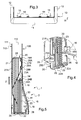
- each chute section 100 is a profile which extends in length along the vertical axis Z and which has a U-shaped cross section. It comprises a bottom wall 111 bordered by two lateral wings 112 for internally delimit a cable housing 116.
- the bottom wall 111 of the base 110 has an outer face to be applied against the wall and an inner face which carries two first longitudinal ribs 114 and, on either side of these two longitudinal ribs 114, two longitudinal second ribs 117 extending along the inner face of the lateral wings 112.
- the first longitudinal ribs 114 have mushroom-shaped cross-sections, with a foot that rises from the inner face of the bottom wall 111 of the base 110, perpendicular thereto, and an arched cap. -circle. These first longitudinal ribs 114 and allow to report two partition walls (not shown) in the cable housing 116 to separate this housing into insulated compartments that can accommodate different types of cables.
- the second longitudinal ribs 117 have meanwhile rectangular cross sections. They each extend a short distance from one of the lateral wings 112 of the base 110, so as to delimit with it a groove 117A.
- the two side wings 112 of the base 110 comprise returns 115 directed towards each other, which extend substantially in the same plane as the closure cover.
- the longitudinal opening of the base 110 is bordered by two longitudinal reentrant walls 119, parallel to each other and parallel to the two lateral wings 112 of the base 110.
- Each re-entrant wall 119 is attached to the rear face of the edge. free of a return 115, perpendicular to it.
- Each reentrant wall 119 thus extends into the cable housing 116, under the corresponding return 115.
- This groove 115A has a width equal to that of the grooves 117A delimited by the second longitudinal ribs 117.
- the longitudinal opening of the base 110 defined above is provided with two clipping strips adapted to allow the mounting of the closure cover (not shown).
- each clipping band here comprises a longitudinal wing attached by a spacer to the free inner end of the corresponding re-entrant wall 119.
- Each longitudinal flange and each associated spacer are located inside the base 110 at a distance from the rear face of the corresponding return 115 of the base 110.
- Each spacer defines with the lateral flange 112 and the corresponding inward wall 119, a longitudinal groove 118A. open towards the front of the base 110.
- the closure lid of the base 110 is a profile which is in the form of a flat plate.
- each closure cover When each closure cover is mounted on the base 110 to seal the cable housing 116, its front face extends to the outcrop of the front face of the returns 115 of the base 110.
- the chute sections 100 have standard lengths strictly less than the height of the wall to which they are attached.
- Extension accessory 2; 52 then makes it possible to complete the length of the chute section or sections, such that the length of the chute 1; 51 adjusts automatically to the height of the wall.
- This extension accessory 2; 52 comprises for this purpose at least one support 20; 70 which extends the chute section 100, and at least one cover 10; 60 to relate aesthetically above this support 20; 70 using positioning means 6; 63, to insulate the cable housing 116 from the outside.
- Each support 20; 70 comprises at least one guide element 21; 71 which is mounted movable in translation in the chute section 100, so as to adjust the length thereof to the height of the wall.
- Each guide element 21; 71 is for this purpose arranged to slide in the chute section 100 between a retracted position inside this chute section 100 and a deployed position in the extension of this chute section 100.
- resilient return means 30 are provided; 80 of the guide elements 21; 71 in the deployed position.
- These elastic return means 30 are arranged to support the weight of the chute section 100, so as to maintain the upper end of the chute 1; 51 against the ceiling of the room.
- the extension accessory 52 forms an attachment accessory of two aligned chute sections 100, interposed between these two chute sections 100.
- the chute 1 comprises a single chute section 100 of length less than the height of the wall on which it is attached.
- the extension accessory 2 is then positioned on the side of the lower end of the chute section, so as to be more easily accessible.
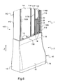
- the extension accessory 2 comprises two separate supports 20, each made in one piece by molding an insulating material such as plastic. These two supports 20 are here identical and from the same mold and therefore have a reduced manufacturing cost.
- each support 20 comprises mainly a rigid wing 21 of small thickness, reinforced on both sides by stiffening ribs.
- This rigid wing 21 has a low end portion 29 (or “outer end portion”) arranged to bear against the ground, an upper end portion 28 (or “inner end portion”) to engage in the chute section 100, a front edge 27B facing the hood 10, and an opposite rear edge 27A.
- the upper end portion 28 of the rigid wing 21 is here arranged to guide the support 20 in the chute section 100. It thus forms the guide member of the support 20 corresponding.
- the front 27B and rear 27A slices of the upper end portion 28 of the rigid wing 21 can thus be engaged and slide in these grooves 115A, 117A.
- the rigid wing 21 can freely navigate in the base 110, from the deployed position (shown in FIG. figure 5 ) in which only its upper end portion 28 is engaged in the chute section 100, to the retracted position in which only its lower end portion 29 projects out of the chute section 100.
- Each support 20 here comprises means for holding the upper end portion 28 of the rigid wing 21 in the chute section 100.
- These holding means comprise two elastically deformable tongues 28B ( figure 5 ) housed in two notches 28A formed in the front edge 27B of the rigid wing 21, on the side of its upper end portion 28.
- These two resiliently deformable tabs 28B are arranged to deform in flexion against the rear faces of the returns 115 of the base 110 during the introduction of the rigid wing 21 in the chute section 100.
- these resiliently deformable tabs 28B facilitate the introduction of the chute 1 against the wall by allowing the installer to handle the chute 1 without paying attention that the supports 20 do not escape the trunking section 100.
- each support 20 has a foot 22 ( figure 4 ) attached to the lower end portion 29 of the rigid wing 21.
- This foot 22 is here in the form of a rod of rectangular section which extends in length from the rear edge 27A of the rigid wing 21 to the front of its front edge 27B.
- This foot 22 carries on each of its flanks two horizontal legs 22A of triangular shapes that optimize the base of the support 20 on the ground.
- Each support 20 further comprises fastening means 25 arranged to secure the lower end portion 29 of the rigid wing 21 on the wall.
- These fixing means 25 comprise here an S-shaped plate which extends in a plane orthogonal to the plane of the rigid wing 21, and whose ends and the center are connected to the rear edge 27A of the rigid wing 21 forming on either side thereof two receiving openings 25A, 25B of two fixing screws (not shown).
- each support 20 is equipped with its own elastic return means 30 to return its rigid wing 21 in the deployed position.
- the elastic return means of each rigid wing 21 comprise in this case a simple compression spring 30, inexpensive, interposed between an outer portion of the support 20 (the foot 22) and a portion of the trough section 100, coming from formation by molding in one piece with this chunk section 100 (the lower end of the section).
- the compression springs 30 of the two supports 20 have such stiffness that when compressed by 1 cm, the sum of the forces exerted by the springs is greater than the weight of the chute section 100.
- the two compression springs 30 are adapted maintain the upper end of the chute section 100 against the ceiling.
- each support 20 comprises a guide rod 23 on which is engaged one of the compression springs 30.
- This guide rod 23 has a cross-shaped cross section and rises from the foot 22 of the support 20, parallel to the rigid wing 21, to near the high end portion 28 of this rigid wing 21.
- the guide rod 23 is here housed in a notch 23A ( figure 5 ) formed by a narrowing width of the rigid wing 21.
- this guide rod 23 runs along the front edge 27B of the rigid wing 21, so that it does not form an obstacle to the sliding of the support 20 in the base 110 of the chute section 100.
- the guide rod 23 is more precisely arranged so that, when the rigid wing 21 slides from its extended position to its position retracted into the chute section 100, the guide rod 23 engages in the groove 115A formed by the return 115 and the corresponding re-entrant wall 119 of the chute section 100.
- the free end of the guide rod 23 is equipped with retaining means 24. of the compression spring 30.
- These retaining means are here formed by two flexible tabs 24A, 24B in flexion, oriented so as to form an arrow with the guide rod 23.
- these two tabs 24A, 24B allow the engagement of the compression spring 30 on the guide rod 23 but prohibit the extraction of the compression spring 30 from the guide rod 23.
- a single U-shaped sectional shaped cover 10 with a front wall 11 and two side walls 12. Its cross section has an increasing size from its high end to its low end .
- Its upper end portion 18 more particularly has a section whose size is adjusted so that its side walls 12 are applied against the outer faces of the lateral wings 112 of the base 110 of the chute section 100 and so that its front wall covers the closing cover of this chute section 100.
- Its lower end portion 19 has a larger section, so that it covers all of the two supports 20 including their feet 22.
- this hood 10 is moreover strictly greater than the maximum deflection of the rigid wing 21 between its deployed position and its position retracted into the chute section 100.
- This cover 10 is made in one piece by molding an insulating material such as plastic.
- the means for positioning and guiding the cover 10 on the supports 20 comprise, on the cover 10, two flanges 16 of U section which extend from the inner face of the front wall 11 of the cover 10, perpendicular to the latter, towards the supports 20. They comprise in correspondence, on each support 20, a vertical finger 26 which rises from the free end of the foot 22, perpendicular to it.
- each flange 16 here comprises an inclined flange 16A which forms a guide ramp for the vertical fingers 26.
- the vertical fingers 26 When placing the cover 10 on the supports 20, the vertical fingers 26 thus make it possible to guide the cover 10 in a suitable position, against the wall and in the extension of the chute section 100.
- the fixing means 14, 15 of the cover 10 on the chute section 100 comprise, on the one hand, latching means 15 of the cover 10 on the lateral flanges 112 of the chute section 100, and, on the other hand , attachment means 14 of the cover 10 to the rear face of the closure cover chute section 100.
- the latching means comprise two tabs 15 which extend from the upper end portion 18 of the rear face of the front wall 11 of the cap 10, perpendicularly thereto, in the direction of the bottom wall 111. of the base of the chute section 100. These two lugs 15 comprise on their end edges teeth arranged to snap into the grooves 118B provided on the facing faces of the reentrant walls 119 of the base 110.
- latching means 15 make it possible to maintain the hood 10 on the chute section 100, while the installer installs the closure lid on the base 110 of the chute section 100.
- the attachment means comprise four tongues 14 which extend along the longitudinal axis of the cap 10, from the end portion 18 of the rear face of the front wall 11 of the cover 10, to beyond the end of the front wall 11 of the cover 10.
- the assembly of the chute 1 is carried out as follows.
- the compression springs 30 Prior to the introduction of the chute 1 against the wall, the compression springs 30 are engaged on the guide rods 23 of the supports 20.
- the rigid wings 21 of the supports 20 are then threaded into the grooves 115A, 117A of the base 110 from the chute section 100 to the deployed position in which the compression springs 30 come into contact with the corresponding end of the base 110 of the trunking section 100 and in which the elastically deformable tongues 28B of the supports 20, deformed in flexion, maintain the supports 20 in the base 110.
- the base 110 of the chute section 100 is then placed against the wall.
- the installer positions the feet 22 of the supports 20 against the ground. It then exerts a substantially vertical force on the base 110 so as to compress the compression springs 30 and to slide the rigid wings 21 of the supports in the base 110 to the retracted position.
- the total length of the base 110 equipped with the two supports 20 is thus reduced, the installer can correctly position the chute section 100 against the wall.
- the installer releases his effort in such a way that the two compression springs 30 push the base 110 of the chute section 100 upwards, resting against the ceiling.
- the base 110 of the chute section 100 equipped with the two supports 20 is thus held fixed against the wall by the compression springs 30.
- the supports 20 are then easily screwed to the wall by means of four screws engaged in the four openings 25A, 25B.
- the cover 10 is then placed on the supports 20, by engaging its flanges 16 on the vertical fingers 26 of the supports 20 and then pushing its upper end 18 against the base 110 of the chute section 100, so that the teeth of its two lugs 15 snap into the grooves 118B provided on the faces facing the two reentrant walls 119 of the base 110.
- closure cover of the base 110 cut to the appropriate length according to the possible installation of an electrical panel (not shown in the figures), is attached to the base 110 in such a way that one its end edges is applied against the ceiling and that its opposite end edge engages between the front wall 11 and the tabs 14 of the cover 10.
- the cover 10 is devoid of fixing means adapted to cooperate with the base 110 of the chute section 100.
- hooking means 14 on the rear face of the closure lid of the chute section 100, and, on the other hand, fastening means 16 ', 26' on the supports 20. .
- the attachment means formed by four vertical tabs 14, are here identical to those shown in FIG. figure 1 .
- the fixing means 16 ', 26' represented on the Figures 8 and 9 , as for them, present a different architecture.
- These fastening means comprise, on each support 20, a lashing pin 26 'which rises vertically from the free end of the foot 22, perpendicular to it.
- Each lashing pin 26 ' has an arrow-shaped cross section oriented towards the hood 10.
- These fastening means comprise in correspondence, on the cover 10, two pairs of tabs 16 'which extend from the lower end portion 19 of the rear face of the front wall 11 of the cover 10, perpendicularly to that ci, in the direction of the lashing fingers 26 'of the supports 20.
- the lugs 16' of each pair extend at a short distance from one another and comprise on their end edges snap-in teeth -a-vis.
- the ratchet teeth of the tabs 16 'of each pair are arranged to hang on either side of the arrow formed by the corresponding lashing finger 26' in order to immobilize the cover 10 on the supports 20.
- the two supports of the extension accessory are not identical.
- the legs of the supports are equipped with horizontal legs of triangular shapes on the side of their internal flanks vis-à-vis.
- the plates of the means for fixing the supports on the wall also extend only on the side of the inner faces of the rigid wings 21 vis-à-vis.
- the chute 1 comprises two chute sections 100 to be connected in the extension of one another. These two chute sections 100 have lengths that are indifferently identical or different, but whose sum is less than the height of the wall on which they are reported. The extension accessory 52 is then interposed between these two chute sections 100 to extend them.
- the extension accessory 52 has a single support 70, and two covers 60 to report on either side of the support 70.
- These three elements 60, 70 are each made in one piece by molding an insulating material such as plastic.
- These supports 70 and covers 60 are profiles which extend in length along the vertical axis Z and which each have a horizontal plane of symmetry. They therefore each have two end portions 68, 69, 78, 79 of identical shapes, including a high end portion 68, 78 arranged to be attached to one of the chute sections 100 (the upper section) and a low end portion 69, 79 arranged to be attached to the other chute section 100 (the lower section).
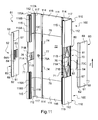
- the support 70 has a U-shaped cross-section. It thus comprises a bottom wall 72 and two lateral flanks 71.
- Its bottom wall 72 is flat and has a width equal to the distance separating the two longitudinal second ribs 117 from the bottom wall 111 of each base 110 chute section 100.
- the bottom wall 72 of the support 70 also has four longitudinal slots 74, including two upper slots arranged to slide on the first two longitudinal ribs 114 of the base 110 of the upper chute section 100, and two lower slots arranged to slide on both. first longitudinal ribs 114 of the base 110 of the lower chute section 100.
- These longitudinal slots 74 high and low are aligned in pairs but do not communicate. They are separated by rigid portions 77 allowing the bottom wall 72 of the support 70 to be in the form of a single piece.
- These longitudinal slots 74 have lengths sufficient to that the support 70 can navigate in each base 110 to the retracted position, in which more than one third of the length of the support 70 is engaged inside this base 110.
- the bottom wall 72 also has means 75 for fixing the support 70 to the wall.
- These fastening means 75 here comprise two receiving apertures 75A, 75B of two fastening screws (not shown), located at the mid-length of this bottom wall 72, on either side of the two rigid parts 77.
- the lateral flanks 71 of the support 70 here form two guiding elements of the support 70 in the chute sections 100.
- These two rigid wings 71 are arranged to guide the sliding of the support 70 in the bases 110 of the two chute sections 100. To this end, they have equal widths, with play, at the height of the lateral wings 112 of the bases 110, and of equal thickness, within play, to the width of the grooves 115A, 117A formed by the second longitudinal ribs 117 and by the returns 115 and the reentrant walls 119 of the bases 110.
- the rigid wings 71 can freely navigate in the base 110 of the chute section 100, from the deployed position ( figure 11 ) to the retracted position.
- These rigid wings 71 each comprise a central portion 71A square which extends in a plane slightly offset outwardly of the support 70 relative to the plane of the remainder of the rigid wing.
- This central portion 71A thus forms two shoulders 71 B respectively facing upwards and downwards of the support 70.
- These two shoulders 71 B constitute abutments against which the ends of the bases 110 of the two chute sections 100 bear when the wings rigid 71 are in the retracted position in these chutes sections 100.
- the elastic return means 80 of the rigid wings 71 in the deployed position comprise four compression springs 81, 82 interposed between an outer portion 73C of the support 70 and the end of one or other of the sections. 100 chute.
- the bottom wall 72 is connected to the rigid flanges 71 of the support 70 by two junction regions 72C in the form of a gutter of quarter-circle section open towards the outside of the support 70.
- Two compression springs 81, 82 are housed in each channel 72C.
- the support 70 comprises four guide rods 73A, 73B on each of which is engaged one of the compression springs 81, 82.
- Each guide rod 73A, 73B extends from one of the faces of one of the two lamellae 73C, inside one of the grooves 72C, to near the high end portion. or low of the support 70. Thus, the guide rods 73A, 73B do not form an obstacle to the sliding of the support 70 in the bases 110 of the chute sections 100.
- the covers 60 have identical shapes and are arranged to be attached to the outer faces of the two rigid wings 71 of the support 70. They have the same lengths as the support 70.
- Each cover 60 has an L-shaped cross-section, with a flat main wall 61 to be applied against one of the rigid flanges 71 of the support 70, and a front flange 62 curved at right angles to cover the edges of the rigid flanges 71 of the support 70.
- Each cover 60 is further arranged to cover with its upper ends 68 and lower 69 the lateral flanges 112 of the bases 110 of the two chute sections 100.
- each cover 60 comprises, on the one hand, positioning means 63 on the support 70, and, on the other hand, fastening and catching means 64 arranged to be fixed and hooked to the cover closing sections chute 100.
- each cover 60 on the support 70 here comprise a tongue 63 which extends from the inner face of the main wall 61 of the cover 60, perpendicular to it, and which is bent at right angles. towards the bottom wall 72 of the support 70.
- each rigid wing 71 of the support 70 comprises in correspondence a generally rectangular opening 76, through which the curved portion of the tongue 63 of the cover 60 can engage.
- each cover 60 to the closure cover comprise a tongue 64 which extends from the end edge 67 of the front edge 62 of the cover 60, and which is folded U to form a groove 64A open towards the front of the chute 51.
- This groove 64A is arranged to be located in the extension of the longitudinal grooves 118A provided on the reentrant walls 119 of the bases 110 of the two chute sections 100.
- the mounting of the chute 51 is made in the following manner.
- the compression springs 81, 82 Prior to the introduction of the chute 51 against the wall, the compression springs 81, 82 are engaged on the guide rods 73A, 73B of the support 70. The rigid wings 71 of the support 70 are then threaded into the grooves 115A, 117A of the bases 110 of the two chute sections 100 to the deployed position in which the compression springs 81, 82 come into contact with the corresponding ends of the bases 110.
- the bases 110 of the two chute sections 100, between which is interposed the support 70, are then placed against the wall.
- the installer compresses the compression springs 81, 82 by bringing the two bases 110 closer to each other. It then positions this assembly against the wall, then releases its effort in such a way that the compression springs 81, 82 push the bases 110 of the two trunking sections 100 respectively to the ground and to the ceiling.
- the support 70 is then easily screwed to the wall by means of two screws engaged in the two receiving openings 75A, 75B.
- the hoods 60 are then placed on the support 70, engaging their tongues 63 in the openings 76 provided on the rigid wings 71 of the support 70.
- closure lid of the base 110 cut to the appropriate length, is attached to the two bases 110 so that it completely covers them and it also covers the extension accessory 52.
- the legs of engagement of the closure cap engage in the tabs 64 of the covers 60 to immobilize them.
- the extension accessory used as a tip at the end of a chute section has not two supports ( figure 1 ) but on the contrary a unique support of the type of represented on the figure 10 .
- extension accessory used as a junction accessory interposed between two chute sections has not a support ( figure 10 ), but on the contrary two distinct supports of the type of those represented on the figure 1 .
- extension accessories on the same chute section, by arranging two extension accessories (identical or not) at both ends of this chute section.
Landscapes
- Engineering & Computer Science (AREA)
- Architecture (AREA)
- Civil Engineering (AREA)
- Structural Engineering (AREA)
- Connector Housings Or Holding Contact Members (AREA)
Applications Claiming Priority (1)
| Application Number | Priority Date | Filing Date | Title |
|---|---|---|---|
| FR0903396A FR2947965B1 (fr) | 2009-07-09 | 2009-07-09 | Accessoire de prolongement d'un troncon de goulotte |
Publications (2)
| Publication Number | Publication Date |
|---|---|
| EP2273636A1 true EP2273636A1 (de) | 2011-01-12 |
| EP2273636B1 EP2273636B1 (de) | 2014-05-07 |
Family
ID=41667158
Family Applications (1)
| Application Number | Title | Priority Date | Filing Date |
|---|---|---|---|
| EP20100290305 Active EP2273636B1 (de) | 2009-07-09 | 2010-06-08 | Verlängerungszubehörteil eines Teilstücks einer Ablaufrinne |
Country Status (2)
| Country | Link |
|---|---|
| EP (1) | EP2273636B1 (de) |
| FR (1) | FR2947965B1 (de) |
Cited By (1)
| Publication number | Priority date | Publication date | Assignee | Title |
|---|---|---|---|---|
| EP2434597A3 (de) * | 2010-09-25 | 2012-04-25 | Tehalit GmbH | Kabelkanalsystem mit Wandanschlussblende |
Citations (4)
| Publication number | Priority date | Publication date | Assignee | Title |
|---|---|---|---|---|
| DE3447646A1 (de) * | 1984-12-28 | 1986-07-10 | Albert 4270 Dorsten Stewing | Kabelverzweigerschrank |
| FR2772106A1 (fr) | 1997-12-10 | 1999-06-11 | Professional General Elect | Poteau destine a etre positionne verticalement, entre le sol et le plafond, notamment pour assurer l'alimentation d'un poste de travail, et procede pour la mise en place d'un tel poteau |
| US6172298B1 (en) * | 1999-04-08 | 2001-01-09 | Steven D. Norvelle | Telescoping electrical distribution panel |
| FR2902245A1 (fr) | 2006-06-09 | 2007-12-14 | Bocchiotti S P A Societa Per L | Accessoire pouvant etre raccorde a une goulotte destinee a contenir des cables electriques |
-
2009
- 2009-07-09 FR FR0903396A patent/FR2947965B1/fr not_active Expired - Fee Related
-
2010
- 2010-06-08 EP EP20100290305 patent/EP2273636B1/de active Active
Patent Citations (4)
| Publication number | Priority date | Publication date | Assignee | Title |
|---|---|---|---|---|
| DE3447646A1 (de) * | 1984-12-28 | 1986-07-10 | Albert 4270 Dorsten Stewing | Kabelverzweigerschrank |
| FR2772106A1 (fr) | 1997-12-10 | 1999-06-11 | Professional General Elect | Poteau destine a etre positionne verticalement, entre le sol et le plafond, notamment pour assurer l'alimentation d'un poste de travail, et procede pour la mise en place d'un tel poteau |
| US6172298B1 (en) * | 1999-04-08 | 2001-01-09 | Steven D. Norvelle | Telescoping electrical distribution panel |
| FR2902245A1 (fr) | 2006-06-09 | 2007-12-14 | Bocchiotti S P A Societa Per L | Accessoire pouvant etre raccorde a une goulotte destinee a contenir des cables electriques |
Cited By (1)
| Publication number | Priority date | Publication date | Assignee | Title |
|---|---|---|---|---|
| EP2434597A3 (de) * | 2010-09-25 | 2012-04-25 | Tehalit GmbH | Kabelkanalsystem mit Wandanschlussblende |
Also Published As
| Publication number | Publication date |
|---|---|
| FR2947965B1 (fr) | 2011-11-11 |
| FR2947965A1 (fr) | 2011-01-14 |
| EP2273636B1 (de) | 2014-05-07 |
Similar Documents
| Publication | Publication Date | Title |
|---|---|---|
| FR3000309A1 (fr) | Boite electrique d'encastrement a fixation automatique sur une paroi | |
| EP3138166B1 (de) | Elektromodul zum einschnappen in eine elektrodose | |
| EP2456032B1 (de) | Vorrichtung zum Verstauen von Stromkabeln | |
| EP1071183A1 (de) | Träger für elektrisches Gerät anzubringen auf einen Kabelkanal | |
| EP2273636B1 (de) | Verlängerungszubehörteil eines Teilstücks einer Ablaufrinne | |
| EP3555975A1 (de) | System mit einer trägerschiene und einer platte, die zur befestigung an einem träger und zur immobilisierung der unter dem träger stehenden schiene konfiguriert ist | |
| EP2369699B1 (de) | Elektrischer Verteiler- oder Schaltkasten, der eine entfernbare Schienenauflagerung für die Montage von elektrischen Geräten umfasst | |
| EP2146363A1 (de) | Modulares Elektrogerät, das mit einer Etikettenschutzhaube und einer Etikettenzughalterung ausgestattet ist | |
| EP0838885B1 (de) | Halteklammer für Kabelrinnen und zugehörige Kabelrinne | |
| FR2679939A1 (fr) | Panneau monobloc pour cloison amovible a joints creux ou plats, cloison correspondante et son procede de pose. | |
| EP2456031B1 (de) | Elektrische Installation, die ein verschiebbares Gerät in einer Wandöffnung enthält | |
| FR2822181A1 (fr) | Systeme de plinthe pour un support et profile pour un tel systeme | |
| EP1617155B1 (de) | Lüftungsgitter | |
| EP2341589B1 (de) | Vorrichtung zur Montage eines Gehäuseständers am hinteren Teil eines Stromverteilungskastens, und mit einer solchen Vorrichtung ausgestatteter Stromverteilungskasten | |
| EP1385244B1 (de) | Dose für elektrisches Gerät zur Montage entlang eines Kabelkanals | |
| EP1744424A1 (de) | Zubehör mit variabler Länge für elektrischen Führungskanal und elektrische Anordnung mit einem elektrischen Führungskanal sowie mit eienm solchen Zubehör | |
| EP0848470B1 (de) | Kanal für elektrische Anlage und Verwendung | |
| EP4455429A1 (de) | Sicht- oder verdunkelungspaneel für starre gitterzäune und befestigungsverfahren dafür | |
| EP2422416B1 (de) | Höheneinstellbare bodendose | |
| EP2264255B1 (de) | Trennwandstruktur, insbesondere einer Hohltrennwand | |
| EP2688166A1 (de) | Zubehörteil zum Verbinden von zwei Endstücken eines Längsträgers eines Hohlwandtragwerks | |
| FR2965420A1 (fr) | Accessoire electrique monte mobile en translation dans une ouverture pratiquee dans une paroi | |
| EP2434599A1 (de) | Elektrisches verschiebbares Zubehör, das in eine Wandöffnung eingebaut ist | |
| EP1357652A1 (de) | Kanal mit mindestens einer transversalen Steifheitsvorrichtung | |
| EP1170844A1 (de) | Einrichtung zum halbversenkten Einbau von mindestens einem Gerät in einen Kabelkanal mit einer kleineren Tiefe |
Legal Events
| Date | Code | Title | Description |
|---|---|---|---|
| PUAI | Public reference made under article 153(3) epc to a published international application that has entered the european phase |
Free format text: ORIGINAL CODE: 0009012 |
|
| AK | Designated contracting states |
Kind code of ref document: A1 Designated state(s): AL AT BE BG CH CY CZ DE DK EE ES FI FR GB GR HR HU IE IS IT LI LT LU LV MC MK MT NL NO PL PT RO SE SI SK SM TR |
|
| AX | Request for extension of the european patent |
Extension state: BA ME RS |
|
| 17P | Request for examination filed |
Effective date: 20110518 |
|
| GRAP | Despatch of communication of intention to grant a patent |
Free format text: ORIGINAL CODE: EPIDOSNIGR1 |
|
| INTG | Intention to grant announced |
Effective date: 20140116 |
|
| GRAS | Grant fee paid |
Free format text: ORIGINAL CODE: EPIDOSNIGR3 |
|
| GRAA | (expected) grant |
Free format text: ORIGINAL CODE: 0009210 |
|
| AK | Designated contracting states |
Kind code of ref document: B1 Designated state(s): AL AT BE BG CH CY CZ DE DK EE ES FI FR GB GR HR HU IE IS IT LI LT LU LV MC MK MT NL NO PL PT RO SE SI SK SM TR |
|
| REG | Reference to a national code |
Ref country code: GB Ref legal event code: FG4D Free format text: NOT ENGLISH |
|
| REG | Reference to a national code |
Ref country code: AT Ref legal event code: REF Ref document number: 667326 Country of ref document: AT Kind code of ref document: T Effective date: 20140515 |
|
| REG | Reference to a national code |
Ref country code: IE Ref legal event code: FG4D Free format text: LANGUAGE OF EP DOCUMENT: FRENCH |
|
| REG | Reference to a national code |
Ref country code: DE Ref legal event code: R096 Ref document number: 602010015797 Country of ref document: DE Effective date: 20140618 |
|
| REG | Reference to a national code |
Ref country code: AT Ref legal event code: MK05 Ref document number: 667326 Country of ref document: AT Kind code of ref document: T Effective date: 20140507 |
|
| REG | Reference to a national code |
Ref country code: NL Ref legal event code: VDEP Effective date: 20140507 |
|
| REG | Reference to a national code |
Ref country code: LT Ref legal event code: MG4D |
|
| PG25 | Lapsed in a contracting state [announced via postgrant information from national office to epo] |
Ref country code: FI Free format text: LAPSE BECAUSE OF FAILURE TO SUBMIT A TRANSLATION OF THE DESCRIPTION OR TO PAY THE FEE WITHIN THE PRESCRIBED TIME-LIMIT Effective date: 20140507 Ref country code: NO Free format text: LAPSE BECAUSE OF FAILURE TO SUBMIT A TRANSLATION OF THE DESCRIPTION OR TO PAY THE FEE WITHIN THE PRESCRIBED TIME-LIMIT Effective date: 20140807 Ref country code: GR Free format text: LAPSE BECAUSE OF FAILURE TO SUBMIT A TRANSLATION OF THE DESCRIPTION OR TO PAY THE FEE WITHIN THE PRESCRIBED TIME-LIMIT Effective date: 20140808 Ref country code: CY Free format text: LAPSE BECAUSE OF FAILURE TO SUBMIT A TRANSLATION OF THE DESCRIPTION OR TO PAY THE FEE WITHIN THE PRESCRIBED TIME-LIMIT Effective date: 20140507 Ref country code: IS Free format text: LAPSE BECAUSE OF FAILURE TO SUBMIT A TRANSLATION OF THE DESCRIPTION OR TO PAY THE FEE WITHIN THE PRESCRIBED TIME-LIMIT Effective date: 20140907 Ref country code: LT Free format text: LAPSE BECAUSE OF FAILURE TO SUBMIT A TRANSLATION OF THE DESCRIPTION OR TO PAY THE FEE WITHIN THE PRESCRIBED TIME-LIMIT Effective date: 20140507 |
|
| PG25 | Lapsed in a contracting state [announced via postgrant information from national office to epo] |
Ref country code: AT Free format text: LAPSE BECAUSE OF FAILURE TO SUBMIT A TRANSLATION OF THE DESCRIPTION OR TO PAY THE FEE WITHIN THE PRESCRIBED TIME-LIMIT Effective date: 20140507 Ref country code: PL Free format text: LAPSE BECAUSE OF FAILURE TO SUBMIT A TRANSLATION OF THE DESCRIPTION OR TO PAY THE FEE WITHIN THE PRESCRIBED TIME-LIMIT Effective date: 20140507 Ref country code: HR Free format text: LAPSE BECAUSE OF FAILURE TO SUBMIT A TRANSLATION OF THE DESCRIPTION OR TO PAY THE FEE WITHIN THE PRESCRIBED TIME-LIMIT Effective date: 20140507 Ref country code: ES Free format text: LAPSE BECAUSE OF FAILURE TO SUBMIT A TRANSLATION OF THE DESCRIPTION OR TO PAY THE FEE WITHIN THE PRESCRIBED TIME-LIMIT Effective date: 20140507 Ref country code: SE Free format text: LAPSE BECAUSE OF FAILURE TO SUBMIT A TRANSLATION OF THE DESCRIPTION OR TO PAY THE FEE WITHIN THE PRESCRIBED TIME-LIMIT Effective date: 20140507 Ref country code: LV Free format text: LAPSE BECAUSE OF FAILURE TO SUBMIT A TRANSLATION OF THE DESCRIPTION OR TO PAY THE FEE WITHIN THE PRESCRIBED TIME-LIMIT Effective date: 20140507 |
|
| PG25 | Lapsed in a contracting state [announced via postgrant information from national office to epo] |
Ref country code: PT Free format text: LAPSE BECAUSE OF FAILURE TO SUBMIT A TRANSLATION OF THE DESCRIPTION OR TO PAY THE FEE WITHIN THE PRESCRIBED TIME-LIMIT Effective date: 20140908 |
|
| PG25 | Lapsed in a contracting state [announced via postgrant information from national office to epo] |
Ref country code: RO Free format text: LAPSE BECAUSE OF FAILURE TO SUBMIT A TRANSLATION OF THE DESCRIPTION OR TO PAY THE FEE WITHIN THE PRESCRIBED TIME-LIMIT Effective date: 20140507 Ref country code: EE Free format text: LAPSE BECAUSE OF FAILURE TO SUBMIT A TRANSLATION OF THE DESCRIPTION OR TO PAY THE FEE WITHIN THE PRESCRIBED TIME-LIMIT Effective date: 20140507 Ref country code: SK Free format text: LAPSE BECAUSE OF FAILURE TO SUBMIT A TRANSLATION OF THE DESCRIPTION OR TO PAY THE FEE WITHIN THE PRESCRIBED TIME-LIMIT Effective date: 20140507 Ref country code: CZ Free format text: LAPSE BECAUSE OF FAILURE TO SUBMIT A TRANSLATION OF THE DESCRIPTION OR TO PAY THE FEE WITHIN THE PRESCRIBED TIME-LIMIT Effective date: 20140507 Ref country code: DK Free format text: LAPSE BECAUSE OF FAILURE TO SUBMIT A TRANSLATION OF THE DESCRIPTION OR TO PAY THE FEE WITHIN THE PRESCRIBED TIME-LIMIT Effective date: 20140507 |
|
| REG | Reference to a national code |
Ref country code: CH Ref legal event code: PL |
|
| REG | Reference to a national code |
Ref country code: DE Ref legal event code: R097 Ref document number: 602010015797 Country of ref document: DE |
|
| PG25 | Lapsed in a contracting state [announced via postgrant information from national office to epo] |
Ref country code: NL Free format text: LAPSE BECAUSE OF FAILURE TO SUBMIT A TRANSLATION OF THE DESCRIPTION OR TO PAY THE FEE WITHIN THE PRESCRIBED TIME-LIMIT Effective date: 20140507 |
|
| PLBE | No opposition filed within time limit |
Free format text: ORIGINAL CODE: 0009261 |
|
| STAA | Information on the status of an ep patent application or granted ep patent |
Free format text: STATUS: NO OPPOSITION FILED WITHIN TIME LIMIT |
|
| REG | Reference to a national code |
Ref country code: IE Ref legal event code: MM4A |
|
| 26N | No opposition filed |
Effective date: 20150210 |
|
| GBPC | Gb: european patent ceased through non-payment of renewal fee |
Effective date: 20140807 |
|
| PG25 | Lapsed in a contracting state [announced via postgrant information from national office to epo] |
Ref country code: CH Free format text: LAPSE BECAUSE OF NON-PAYMENT OF DUE FEES Effective date: 20140630 Ref country code: IT Free format text: LAPSE BECAUSE OF FAILURE TO SUBMIT A TRANSLATION OF THE DESCRIPTION OR TO PAY THE FEE WITHIN THE PRESCRIBED TIME-LIMIT Effective date: 20140507 Ref country code: LI Free format text: LAPSE BECAUSE OF NON-PAYMENT OF DUE FEES Effective date: 20140630 Ref country code: IE Free format text: LAPSE BECAUSE OF NON-PAYMENT OF DUE FEES Effective date: 20140608 |
|
| REG | Reference to a national code |
Ref country code: DE Ref legal event code: R097 Ref document number: 602010015797 Country of ref document: DE Effective date: 20150210 |
|
| REG | Reference to a national code |
Ref country code: FR Ref legal event code: PLFP Year of fee payment: 6 |
|
| PG25 | Lapsed in a contracting state [announced via postgrant information from national office to epo] |
Ref country code: GB Free format text: LAPSE BECAUSE OF NON-PAYMENT OF DUE FEES Effective date: 20140807 Ref country code: SI Free format text: LAPSE BECAUSE OF FAILURE TO SUBMIT A TRANSLATION OF THE DESCRIPTION OR TO PAY THE FEE WITHIN THE PRESCRIBED TIME-LIMIT Effective date: 20140507 |
|
| PG25 | Lapsed in a contracting state [announced via postgrant information from national office to epo] |
Ref country code: MT Free format text: LAPSE BECAUSE OF FAILURE TO SUBMIT A TRANSLATION OF THE DESCRIPTION OR TO PAY THE FEE WITHIN THE PRESCRIBED TIME-LIMIT Effective date: 20140507 |
|
| PG25 | Lapsed in a contracting state [announced via postgrant information from national office to epo] |
Ref country code: SM Free format text: LAPSE BECAUSE OF FAILURE TO SUBMIT A TRANSLATION OF THE DESCRIPTION OR TO PAY THE FEE WITHIN THE PRESCRIBED TIME-LIMIT Effective date: 20140507 Ref country code: MC Free format text: LAPSE BECAUSE OF FAILURE TO SUBMIT A TRANSLATION OF THE DESCRIPTION OR TO PAY THE FEE WITHIN THE PRESCRIBED TIME-LIMIT Effective date: 20140507 |
|
| PG25 | Lapsed in a contracting state [announced via postgrant information from national office to epo] |
Ref country code: BG Free format text: LAPSE BECAUSE OF FAILURE TO SUBMIT A TRANSLATION OF THE DESCRIPTION OR TO PAY THE FEE WITHIN THE PRESCRIBED TIME-LIMIT Effective date: 20140507 |
|
| REG | Reference to a national code |
Ref country code: FR Ref legal event code: PLFP Year of fee payment: 7 |
|
| PG25 | Lapsed in a contracting state [announced via postgrant information from national office to epo] |
Ref country code: HU Free format text: LAPSE BECAUSE OF FAILURE TO SUBMIT A TRANSLATION OF THE DESCRIPTION OR TO PAY THE FEE WITHIN THE PRESCRIBED TIME-LIMIT; INVALID AB INITIO Effective date: 20100608 Ref country code: BE Free format text: LAPSE BECAUSE OF FAILURE TO SUBMIT A TRANSLATION OF THE DESCRIPTION OR TO PAY THE FEE WITHIN THE PRESCRIBED TIME-LIMIT Effective date: 20140630 Ref country code: TR Free format text: LAPSE BECAUSE OF FAILURE TO SUBMIT A TRANSLATION OF THE DESCRIPTION OR TO PAY THE FEE WITHIN THE PRESCRIBED TIME-LIMIT Effective date: 20140507 Ref country code: LU Free format text: LAPSE BECAUSE OF NON-PAYMENT OF DUE FEES Effective date: 20140608 |
|
| REG | Reference to a national code |
Ref country code: FR Ref legal event code: ST Effective date: 20170228 |
|
| PG25 | Lapsed in a contracting state [announced via postgrant information from national office to epo] |
Ref country code: FR Free format text: LAPSE BECAUSE OF NON-PAYMENT OF DUE FEES Effective date: 20160630 |
|
| REG | Reference to a national code |
Ref country code: FR Ref legal event code: RN Effective date: 20170413 |
|
| REG | Reference to a national code |
Ref country code: FR Ref legal event code: FC Effective date: 20170418 |
|
| REG | Reference to a national code |
Ref country code: FR Ref legal event code: PLFP Year of fee payment: 8 |
|
| PG25 | Lapsed in a contracting state [announced via postgrant information from national office to epo] |
Ref country code: FR Free format text: LAPSE BECAUSE OF NON-PAYMENT OF DUE FEES Effective date: 20160630 |
|
| PGRI | Patent reinstated in contracting state [announced from national office to epo] |
Ref country code: FR Effective date: 20170418 |
|
| PG25 | Lapsed in a contracting state [announced via postgrant information from national office to epo] |
Ref country code: MK Free format text: LAPSE BECAUSE OF FAILURE TO SUBMIT A TRANSLATION OF THE DESCRIPTION OR TO PAY THE FEE WITHIN THE PRESCRIBED TIME-LIMIT Effective date: 20140507 |
|
| REG | Reference to a national code |
Ref country code: FR Ref legal event code: PLFP Year of fee payment: 9 |
|
| PG25 | Lapsed in a contracting state [announced via postgrant information from national office to epo] |
Ref country code: AL Free format text: LAPSE BECAUSE OF FAILURE TO SUBMIT A TRANSLATION OF THE DESCRIPTION OR TO PAY THE FEE WITHIN THE PRESCRIBED TIME-LIMIT Effective date: 20140507 |
|
| PGFP | Annual fee paid to national office [announced via postgrant information from national office to epo] |
Ref country code: DE Payment date: 20250520 Year of fee payment: 16 |
|
| PGFP | Annual fee paid to national office [announced via postgrant information from national office to epo] |
Ref country code: FR Payment date: 20250520 Year of fee payment: 16 |