EP2273639A2 - Boîtier d'installation électrique - Google Patents
Boîtier d'installation électrique Download PDFInfo
- Publication number
- EP2273639A2 EP2273639A2 EP10006177.9A EP10006177A EP2273639A2 EP 2273639 A2 EP2273639 A2 EP 2273639A2 EP 10006177 A EP10006177 A EP 10006177A EP 2273639 A2 EP2273639 A2 EP 2273639A2
- Authority
- EP
- European Patent Office
- Prior art keywords
- sleeve
- plate
- parts
- sealing
- supplementary part
- Prior art date
- Legal status (The legal status is an assumption and is not a legal conclusion. Google has not performed a legal analysis and makes no representation as to the accuracy of the status listed.)
- Granted
Links
Images





Classifications
-
- H—ELECTRICITY
- H02—GENERATION; CONVERSION OR DISTRIBUTION OF ELECTRIC POWER
- H02G—INSTALLATION OF ELECTRIC CABLES OR LINES, OR OF COMBINED OPTICAL AND ELECTRIC CABLES OR LINES
- H02G3/00—Installations of electric cables or lines or protective tubing therefor in or on buildings, equivalent structures or vehicles
- H02G3/02—Details
- H02G3/08—Distribution boxes; Connection or junction boxes
- H02G3/088—Dustproof, splashproof, drip-proof, waterproof, or flameproof casings or inlets
-
- H—ELECTRICITY
- H02—GENERATION; CONVERSION OR DISTRIBUTION OF ELECTRIC POWER
- H02G—INSTALLATION OF ELECTRIC CABLES OR LINES, OR OF COMBINED OPTICAL AND ELECTRIC CABLES OR LINES
- H02G3/00—Installations of electric cables or lines or protective tubing therefor in or on buildings, equivalent structures or vehicles
- H02G3/02—Details
- H02G3/08—Distribution boxes; Connection or junction boxes
- H02G3/12—Distribution boxes; Connection or junction boxes for flush mounting
- H02G3/121—Distribution boxes; Connection or junction boxes for flush mounting in plain walls
-
- H—ELECTRICITY
- H02—GENERATION; CONVERSION OR DISTRIBUTION OF ELECTRIC POWER
- H02G—INSTALLATION OF ELECTRIC CABLES OR LINES, OR OF COMBINED OPTICAL AND ELECTRIC CABLES OR LINES
- H02G3/00—Installations of electric cables or lines or protective tubing therefor in or on buildings, equivalent structures or vehicles
- H02G3/22—Installations of cables or lines through walls, floors or ceilings, e.g. into buildings
-
- H—ELECTRICITY
- H02—GENERATION; CONVERSION OR DISTRIBUTION OF ELECTRIC POWER
- H02G—INSTALLATION OF ELECTRIC CABLES OR LINES, OR OF COMBINED OPTICAL AND ELECTRIC CABLES OR LINES
- H02G3/00—Installations of electric cables or lines or protective tubing therefor in or on buildings, equivalent structures or vehicles
- H02G3/02—Details
- H02G3/04—Protective tubing or conduits, e.g. cable ladders or cable troughs
- H02G3/0406—Details thereof
- H02G3/0412—Heat or fire protective means
Definitions
- the invention relates to an electrical installation box or cavity wall box for installation in walls, preferably fire-retardant walls, in particular F-90 walls, wherein the wall has a matching perforation for use of the can, the can mouth side preferably has a flange, the outside in mounting target position on the wall is present, as well as fasteners for fixing to the wall in mounting target position.
- Cavity wall boxes are for example from the DE 20 2006 003 356 U known. Cavity wall boxes are installed in corresponding holes of a cavity wall to allow electrical wiring with installation elements inserted into the cavity wall box.
- Such hollow wall boxes are not suitable to form cable bushings through multilayer hollow walls or a cable entry into the space behind a cavity wall.
- the present invention seeks to provide a can of the generic type, which can be installed in a simple manner by drywall or electricians with conventional tools, so formed the corresponding holes in the wall with the available tools can be and is suitable for the implementation of long molded parts, such as cables, cable bundles or installation tubes.
- the invention proposes that the box is designed as a bottomless sleeve.
- the craftsman an installation element is provided, which he can install using the usual tools for the electrician and / or drywall, because he can use the same tools that are customary and necessary for the installation of hollow wall boxes.
- a corresponding hole in the wall is thus introduced with these tools, in which then inserted the bottomless sleeve can be.
- the bottomless sleeve can be used to guide appropriate wires, cables or pipes through the wall or behind the wall.
- a sealing compound is introduced into the sleeve, which surrounds long molded parts guided through the sleeve, in particular cables, cable bundles or one or more installation tubes, and preferably existing gaps between the inner jacket of the sleeve and the one or more Long molding (s) closes.
- Such a sealant can be introduced into the sleeve before installation, so that the sleeve is inserted together with the sealant in the corresponding hole of the wall. It is also possible to first use the sleeve and perform appropriate cables, cable bundles or installation tubes and then introduce into the sleeve or the remaining space sealant.
- the sealing compound consists of a plate or the like disc-like part, which rests on the inside of the sleeve shell and is at least one long-form part tangible or penetrated.
- the sealant is formed by a dimensionally stable plate or the like disk-like part, which in the Sleeve can be inserted or inserted into the sleeve.
- the plate or the disc-like part can be penetrated by such a long-shaped part.
- a corresponding opening can be made by an auxiliary tool such as a screwdriver or the like to facilitate the passage of long moldings.
- the sleeve is made of plastic.
- the sleeve consists of intumescent material or is covered on the inside and / or outside of such material.
- the sealant in particular the existing sealant plate, consists of intumescent material.
- the plate By such a plate of intumescent material, the free cross section of the bottomless sleeve is blocked.
- the plate may have a breakable opening or a preformed opening or areas to be opened by predetermined breaking points.
- the plate In the normal installation state, the plate is closed by its own plate material. If a cable, Cable bundle or conduit is to be performed, so the plate can be opened in the appropriate area to produce an opening, so that a free space is created, through which the corresponding element (cable, cable bundle or installation tube) can be performed.
- the plate material is applied to the jacket of the performed element and on the other hand is supported on the inner shell of the bottomless sleeve.
- the sleeve is then made of normal plastic sprayable.
- the sleeve may consist of intumescent material or be coated therewith.
- the plate consisting of sealing compound has at least one break-out region which can be broken out or separated out and / or at least one penetration region formed by an elastic membrane and / or at least one through Having an elastic ring formed by insertion region.
- the plate may have a break-through or detachable push-through area prepared by predetermined breaking points or the like, or even several such areas for a plurality of elements, such as cables or the like.
- the plate may also have a perforation or the like, which is covered by an elastic membrane, which is integrally formed, for example by means of a two-component method with the plate.
- This elastic membrane or even several such elastic membranes can form a puncture area for corresponding cables or the like.
- the sleeve has a flange edge at its first end.
- This flange edge mounting aid so a Einstecktiefenbegrenzung is achieved because in the mounting position of the flange flange is applied to the outside of the wall in the region of the wall breakthrough.
- the sleeve can also be fixed in the usual way with fastening means on the wall, wherein the same fastening means can be used, the needed and used in the attachment of hollow wall boxes or installation boxes.
- the sleeve has at its second end region a rounded radially outwardly extending collar.
- the sleeve is integrally formed.
- the one-piece design of the sleeve is particularly easy to accomplish, for example, the previously conventional tools for the production of hollow wall boxes can be used, which are to be supplemented insofar as the mold cavity for the formation of the bottom of the cavity wall socket is missing, since the sleeve so bottomless should be trained.
- the sleeve is split longitudinally.
- the sleeve Due to the longitudinal division of the sleeve, it is possible to initially provide these as an open shell, for example, half-shell, so that cables can be inserted. Subsequently, the other parts of the sleeve can be placed and also the plate are introduced into the sleeve thus formed. The sleeve thus formed can then be inserted into the corresponding perforation of the wall. The sleeve is then supported on the hole reveal of the wall, whereby the cohesion of the parts is ensured in cooperation with the plate arranged in the sleeve.
- the parts of the sleeve formed by the longitudinal division have at their edges projections, depressions or the like for pluggable, latchable or push-fit connection of the parts suitable parts.
- This design ensures a precisely fitting supply of the individual parts of the sleeve, optionally with latchable or push-fit parts also a self-retaining cohesion of the parts is ensured before they are inserted into the corresponding hole of the wall.
- the diameter of the sleeve is 68 or 74mm.
- the plate is in one piece.
- the plate is composed of a plurality of plate sections.
- the plate Regardless of whether the plate consists of one piece or is composed of several plate sections, the plate preferably has a plurality of slots, slats or areas of thinned material which serve for the insertion and passage of cables and the like.
- the material of the plate is sufficiently elastic, on the one hand to allow the implementation of such elements and on the other hand to ensure that the plate material is supported substantially non-positively on the shell of the performed element.
- the plate has a thickness of up to one centimeter.
- the plate thickness should be chosen so that on the one hand a stable mounting of the plate is ensured in the sleeve and on the other hand not unnecessarily much material is used for the production of the plate.
- the parts forming the sleeve are pivotally connected to each other via material bridges.
- two half-shell-shaped parts which form the sleeve, connected to each other at a respective end region via a material bridge, so that they allow in the pivoted position the insertion of cables or the like and form a closed sleeve in the pivoted position.
- the plate or each plate section of the plate is pivotally mounted on the sleeve or a part formed by the division of the sleeve part via a material bridge.
- the material bridges consist of elastic, preferably elastomeric material.
- a further preferred embodiment is seen in the fact that the plate or at least one plate section of the plate has open-edge or open to the dividing gap slots and / or formed by an elastic membrane or an elastic ring puncture or push-through an open to the edge of the plate slot or a to the dividing joint has open slot.
- the plate or at least one plate section of the plate has open-edge or open to the dividing gap slots, it is possible to subsequently thread cables or the like, which are already passed through the sleeve on the plate by cables or the like in the open-edged or dividing joint open slots are pressed until they reach their desired position. Subsequently, the plate or the plate section can then be inserted into the sleeve, so that the desired position is reached. Even if the plate or the plate sections has an elastic membrane or an elastic ring, which area serves as a piercing or push-through area for installation elements, an installation facilitation can be created in that these puncture or push-through areas each one to the edge of the Have plate open slot or a dividing joint of the plate members open slot.
- corresponding installation elements such as cables or pipes that are passed through the already installed sleeve, be retrofitted with the plate or the plate section by the plate or the plate section is pressed with the slot on the corresponding part until the part reaches the puncture or push-through, which corresponds to the desired position.
- the plate or plate sections may then be positioned with the penetrating cables or tubing in the sleeve.
- the sleeve has over its length extending predetermined breaking points.
- the sleeve is formed quasi one piece, but it has over its length extending predetermined separation points, so that the same sleeve can be used as an integral element in the corresponding hole alternatively or the sleeve can be separated along the predetermined separation points in sleeve sections, so that cable , which are already guided by the corresponding perforation of the wall, are inserted, the sleeve can be assembled and pressed into the perforation.
- the sleeve has two diametrically opposite over its length extending predetermined breaking points. It can be provided that the predetermined separation points are formed by material areas which are thinned with respect to the sleeve wall.
- the predetermined separation points are formed or bridged by soft-elastic, in particular elastomeric material regions.
- the sleeve can be easily separated with a knife into sections, wherein after the subsequent reassembly of the sleeve parts thus formed the soft elastic, in particular elastomeric material regions seal the adjacent marginal edges of the sleeve.
- the sleeve has an axially projecting from the flange edge or protruding beyond the flange edge supplementary part, by means of which guided through the sleeve cable or the like parts smoke gas tight are.
- the sleeve is preferably made of intumescent material.
- the axially protruding from the flange edge or projecting beyond the flange edge supplementary part is provided, which, after installation, comprises the cable guided through the sleeve or even tubes in a smoke-gas-tight manner. If in such an installed sleeve in the area behind the wall, in which the sleeve is inserted, ie on the side facing away from the flange edge of the sleeve, a fire occurs, so flue gases can not escape through the sleeve, as the guided through the sleeve cable and The like are complemented smoke-tight by the supplementary part.
- the intumescent material inflates and seals in the sleeve in the area between the hole wall of the hole, in which the sleeve is inserted, and the cables carried out completely, so that a fire penetration is prevented.
- the supplementary part is formed integrally with the sleeve.
- the supplementary part is releasably secured to the sleeve.
- the cable can first be passed through the sleeve during installation before the supplementary part is subsequently placed on the sleeve for the purposes of the flue gas seal.
- the sleeve one from the flange edge has protruding neck on which the supplement is plugged or plugged.
- a particularly simple way of assembling the parts is achieved when a bayonet closure forming parts, namely pins and guide and retaining grooves are formed on the neck and on this cooperating parts of the supplementary part.
- a particularly preferred design is seen in that the supplementary part alone or the sleeve are divided longitudinally.
- locking or Verrastkonturen or bolt or notches may be provided at the opposite marginal edges of the items, so that the parts are radially assembled and locked together in the desired mounting position.
- the individual parts formed by longitudinal division are pivotally connected to one another at a dividing joint by at least one material bridge.
- the corresponding material bridge can be provided, about which the individual parts are pivotable, while at the other dividing joint corresponding locking elements can be mounted to lock items together when they are spent in the desired position.
- the supplementary part is a tubular-like molded part of substantially dimensionally stable material, in particular plastic, in the interior of which elastic sealing elements are arranged or formed on the inner jacket, which sealingly close the cross-section of the molded part.
- the supplementary part is a tube-like molded part of dimensionally stable material, its handling and assembly and attachment to the sleeve to realize in a simple manner.
- the flue gas seal is achieved because the performed cable or the like are covered by these sealing elements and the sealing elements adapt well to the jacket of the cable, so that the desired flue gas tightness is achieved.
- the supplementary part consists of two half-shell-like pipe sections, which are assembled or joined together to form a tubular molding, wherein each half-shell-like pipe section has on the inside elastic sealing elements, which complement each other in assembled pipe sections to a sealing washer.
- the supplementary part has internally molded sealing lips or comb-like sealing blades.
- the supplementary part on the inside comprises at least one, preferably radially split elastically deformable sealing body, which is held captive in the assembly target position on the supplementary part.
- a corresponding half of the sealing body may be attached, in the assembly target position, the items form the supplementary part and the sealing body a complete cross-sectional sealing of Supplementary effects. Due to the elasticity of the sealing body it is ensured that it can adapt well to the cable and the like, in order to ensure the smoke gas tightness.
- the supplementary part has on the inside an annular chamber in which the sealing body or the parts of the sealing body is held axially immovable or are.
- sealing elements, sealing body, sealing lamellae or sealing lips are made of flame-retardant or non-combustible material.
- the element for installation in fire-retardant walls, such as F-90 walls is shown.
- the corresponding wall is provided with a suitable perforation for use of this element.
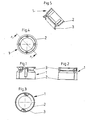
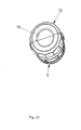
- the element is designed as a bottomless sleeve 1, wherein in this sleeve 1, preferably close to the mouth, a plate 7 is inserted from intumescent material, the at least one, possibly even a plug or fürsteck Schemee 8 for at least one cable or a cable bundle or a Installation tube has.
- a corresponding sleeve 1 is inserted into the corresponding wall opening, wherein in the sleeve 1, the plate 7 is inserted from intumescent material, which is penetrated by a cable or more cables or a cable bundle or an installation tube, so that the plate 7 on the one hand on the jacket of the inserted element and on the other hand on the inner shell of the sleeve 1 is supported.
- the sleeve 1 is made of plastic sprayable.
- the sleeve 1 consists of injectable intumescent material or is covered and lined on the inside and / or outside by such material.
- the sleeve 1 has a flange edge 2 at its first end region. This serves as Einstecktiefenbegrenzung, so that the sleeve when installed in the corresponding hole with the Flange edge 2 can be supported on the wall next to the perforation.
- the sleeve 1 has a radially outwardly extending collar 3. This serves to form a guide for a guided through the sleeve 1 and, for example, at right angles dissipated cable, which can be supported on the rounded surface of the collar 3 and is guided on this.
- the sleeve 1 is formed as a one-piece element.
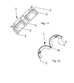
- the sleeve 1 is split longitudinally. In the drawing, only the half shell of the sleeve 1 formed by the central division is shown. In this case, projections 4 or corresponding recesses 5 are formed on the edges formed by the longitudinal division parts of the sleeve 1 so that the identically shaped parts can be assembled to form a sleeve 1, in which case the projections 4 engage in corresponding recesses of the counterpart.
- the securing elements formed by projections and depressions other securing elements, for example latchable securing elements or thrust connecting elements, may also be provided at these edges.
- the diameter of the sleeve 1 is preferably 68 or 74mm, because this measure corresponds to the usual measure of hollow wall boxes. This makes it possible for the user in a simple manner, by means of the usual tools that he has for the installation of hollow wall boxes available to create the Wandungs trimbrüche, in which the sleeve 1 can be used.
- plate 7 of intumescent material may be formed integrally or in several parts.
- a plate has a thickness of up to one centimeter.
- the sleeve 1 forming parts pivotally connected to each other via a material bridge 6.
- cables can be introduced into the sleeve 1, in particular by penetrating the to be arranged in the sleeve plate 7 of intumescent material. Subsequently, the sleeve parts can be pivoted to each other, so that a closed sleeve 1 is formed, as for example in FIG. 1 is shown.
- the intumescent plate 7 is composed of two plate sections, which are connected via material bridges 11 with the sleeve 1.
- the plate sections of the plate 7 can be displaced during pre-assembly in a position as in FIG. 13 shown.
- the sleeve 1 can in the corresponding Hole of the wall can be used and it can be installed through the sleeve 1 through cables or other elements. Subsequently, then the plate sections can be pivoted to each other, so that the sleeve cross-section is closed by these plate sections.
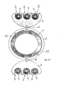
- an arrangement of push-through areas 8 for cables or the like is formed in the plate sections.
- these elements could be ejectable elements or elastomeric elements.
- these elements to the dividing joint of the plate 7 open slots 9, so that, for example, cables can be inserted into this push-through through the slots 9, when the plate parts are pivoted to each other in the desired position.
- the sleeve 1 is indeed formed in one piece, but provided in an area with two extending over its length Solltrennstellen 10, which are diametrically opposed to each other.
- These predetermined separation points 10 are preferably formed by elastomeric material areas, so that they can be separated in a simple manner, for example with a knife blade to disassemble the sleeve 1 in two half-shell elements. When assembling the sleeve parts, these areas then serve as additional sealing elements in the region of the separation points.
- an installation box or cavity wall box is also shown, the is suitable and intended for installation in fire-retardant walls 12, wherein the wall 12 has a suitable perforation for use of the can.
- the box is designed as a bottomless sleeve 1, the mouth side has a flange 2, which in the installed position according to FIG. 18 on the outside of the corresponding wall 12 rests and is supported there.
- This flange edge serves as an abutment for the attachment of the sleeve 1, for example by means of clamping elements, as they are common in hollow wall boxes.
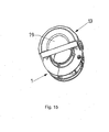
- the supplemental part 13 is releasably attached to the sleeve 1, wherein the sleeve 1 has a flange 14 axially projecting from the flange 14, to which the supplementary part 13 with a corresponding contour can be plugged.
- a bayonet closure-forming parts namely pins 15 and guide or retaining grooves 16 are formed on the neck 14 and on this cooperating parts of the supplementary part 13.
- the retaining grooves 16 open out over guide grooves axially out of the supplementary part in the direction of the sleeve 1, while the retaining grooves extend in the circumferential direction and are preferably slightly skewed so that they form Anzugs vom, provided that they the pin 15 cooperate.
- the sleeve 1 is divided longitudinally, so that there are two half-shell-shaped items, one of which, for example, in FIG. 19 shown in different views.
- the supplementary part 13 is divided longitudinally.
- One of these half-shell-shaped parts, which is formed by the longitudinal division, is in FIG. 21 shown.
- a projection or a hole is formed in the sleeve 1 at the peripheral edge formed by longitudinal division, which engage in each other in assembly target position.
- the items that forms the supplementary part 13 have at their pitch joint locking elements 17, 18, which engage in mounting desired position into each other and ensure the cohesion of the parts.
- the supplementary part 13 is a tube-like molded part made of substantially dimensionally stable material, in particular plastic.
- the interior elastic sealing elements 19 are arranged and held. Alternatively, such sealing elements may also be formed on the inner jacket. In the installation target position, the sealing elements 19 seal the cross-section of the supplementary part 13 forming molding tight.
- the supplementary part 13 consists in particular of two half-shell-like pipe sections, the a tubular molding are assembled. Each half-shell-like pipe section has on the inside corresponding elastic sealing elements 19, which complement each other in assembled pipe sections to a sealing washer.
- the supplementary part 13 has on the inside a radially divided elastically deformable sealing body 19, in particular in FIG FIG. 16 and 17 is apparent. This is held captive in mounting target position on supplementary part 13.
- the supplementary part 13 preferably on the inside an annular chamber 20 in which parts of the sealing body 19 are held axially immovable.
- the sealing body 19 is preferably made of flame-retardant or non-combustible material.
- a cable harness can first be passed through the corresponding perforation of the fire-retardant wall 12. Subsequently, the sleeve 1, which is formed from two half-shells, placed radially on the wire harness and are inserted axially into the perforation of the fire protection wall 12 and fixed thereto. Subsequently, the two half-shells, which form the supplementary part 13, with the half-shell-shaped sealing bodies 19 mounted therein can then be placed radially on the cable sheath and compressed. Subsequently, this preassembled unit is displaced in the direction of the sleeve and fixed to the sleeve 1, for example by the interaction of the pin 15 with the Shutter contours 16. The final assembly situation is in FIG.
Landscapes
- Engineering & Computer Science (AREA)
- Architecture (AREA)
- Civil Engineering (AREA)
- Structural Engineering (AREA)
- Installation Of Indoor Wiring (AREA)
- Connection Or Junction Boxes (AREA)
Priority Applications (2)
| Application Number | Priority Date | Filing Date | Title |
|---|---|---|---|
| DE202010017201U DE202010017201U1 (de) | 2009-07-09 | 2010-06-15 | Elektrische Installationsdose |
| PL10006177T PL2273639T3 (pl) | 2009-07-09 | 2010-06-15 | Instalacyjne gniazdo elektryczne |
Applications Claiming Priority (2)
| Application Number | Priority Date | Filing Date | Title |
|---|---|---|---|
| DE102009032451A DE102009032451A1 (de) | 2009-07-09 | 2009-07-09 | Elektrische Installationsdose |
| DE102009053892A DE102009053892A1 (de) | 2009-07-09 | 2009-11-20 | Elektrische Installationsdose |
Publications (3)
| Publication Number | Publication Date |
|---|---|
| EP2273639A2 true EP2273639A2 (fr) | 2011-01-12 |
| EP2273639A3 EP2273639A3 (fr) | 2016-10-19 |
| EP2273639B1 EP2273639B1 (fr) | 2019-04-24 |
Family
ID=43014450
Family Applications (1)
| Application Number | Title | Priority Date | Filing Date |
|---|---|---|---|
| EP10006177.9A Active EP2273639B1 (fr) | 2009-07-09 | 2010-06-15 | Boîtier d'installation électrique |
Country Status (3)
| Country | Link |
|---|---|
| EP (1) | EP2273639B1 (fr) |
| DE (2) | DE102009053892A1 (fr) |
| PL (1) | PL2273639T3 (fr) |
Cited By (5)
| Publication number | Priority date | Publication date | Assignee | Title |
|---|---|---|---|---|
| US10975567B2 (en) | 2017-12-21 | 2021-04-13 | Reliance Worldwide Corporation | Extendable sleeve for poured concrete deck |
| US11628321B2 (en) | 2015-04-27 | 2023-04-18 | Hilti Aktiengesellschaft | Firestop collar |
| US11655919B2 (en) | 2015-04-27 | 2023-05-23 | Hilti Aktiengesellschaft | Fire protection sleeve |
| US12104737B2 (en) | 2016-10-05 | 2024-10-01 | Hilti Aktiengesellschaft | Line feed-through for feeding a line through a building component |
| US12467559B2 (en) | 2015-07-28 | 2025-11-11 | Hilti Aktiengesellschaft | Air, acoustic and/or fire sealing sleeve insert and air, acoustic and/or fire sealing device |
Families Citing this family (5)
| Publication number | Priority date | Publication date | Assignee | Title |
|---|---|---|---|---|
| DE202011110635U1 (de) | 2011-06-25 | 2015-05-15 | Kaiser Gmbh & Co. Kg | Elektrische Installationsdose |
| DE102011105575B3 (de) * | 2011-06-25 | 2012-09-06 | Kaiser Gmbh & Co. Kg | Elektrische Installationsdose |
| EP2840290B1 (fr) | 2013-08-20 | 2018-11-07 | Kaiser GmbH & Co. KG | Système sous la forme d'une traversée de tubes étanche aux gaz et/ou ignifuge |
| DE102014108551B3 (de) * | 2014-06-17 | 2015-08-27 | Svt Brandschutz Vertriebsgesellschaft Mbh International | Brandschutz für Hohlwanddosen |
| DE102021124092B4 (de) | 2021-09-17 | 2023-07-20 | Obo Bettermann Hungary Kft | Installationsdose sowie Intumeszenzeinsatz dafür |
Citations (1)
| Publication number | Priority date | Publication date | Assignee | Title |
|---|---|---|---|---|
| DE202006003356U1 (de) | 2006-03-03 | 2006-08-31 | Kaiser Gmbh & Co. Kommanditgesellschaft | Intumeszierende elektrische Installationsteile |
Family Cites Families (5)
| Publication number | Priority date | Publication date | Assignee | Title |
|---|---|---|---|---|
| GB2260452B (en) * | 1990-10-10 | 1993-07-21 | Cable Management Systems Ltd | Access closure allowing passage of elongate members |
| GB9803931D0 (en) * | 1998-02-26 | 1998-04-22 | Kovacs Laurence K | Intumescent collar |
| DE19960485A1 (de) * | 1999-12-15 | 2001-06-21 | Hilti Ag | Brandschutzmanschette für Rohre, Kabel u. dgl. |
| ES2280143B1 (es) * | 2006-02-21 | 2008-05-16 | Bsh Electrodomesticos España, S.A. | Dispositivo para el tendido de conductos. |
| DE102009032451A1 (de) | 2009-07-09 | 2011-01-13 | Kaiser Gmbh & Co. Kommanditgesellschaft | Elektrische Installationsdose |
-
2009
- 2009-11-20 DE DE102009053892A patent/DE102009053892A1/de not_active Withdrawn
-
2010
- 2010-06-15 EP EP10006177.9A patent/EP2273639B1/fr active Active
- 2010-06-15 DE DE202010017201U patent/DE202010017201U1/de not_active Expired - Lifetime
- 2010-06-15 PL PL10006177T patent/PL2273639T3/pl unknown
Patent Citations (1)
| Publication number | Priority date | Publication date | Assignee | Title |
|---|---|---|---|---|
| DE202006003356U1 (de) | 2006-03-03 | 2006-08-31 | Kaiser Gmbh & Co. Kommanditgesellschaft | Intumeszierende elektrische Installationsteile |
Cited By (9)
| Publication number | Priority date | Publication date | Assignee | Title |
|---|---|---|---|---|
| US11628321B2 (en) | 2015-04-27 | 2023-04-18 | Hilti Aktiengesellschaft | Firestop collar |
| US11655919B2 (en) | 2015-04-27 | 2023-05-23 | Hilti Aktiengesellschaft | Fire protection sleeve |
| US12083366B2 (en) | 2015-04-27 | 2024-09-10 | Hilti Aktiengesellschaft | Firestop collar |
| US12123534B2 (en) | 2015-04-27 | 2024-10-22 | Hilti Aktiengesellschaft | Fire protection sleeve |
| US12467559B2 (en) | 2015-07-28 | 2025-11-11 | Hilti Aktiengesellschaft | Air, acoustic and/or fire sealing sleeve insert and air, acoustic and/or fire sealing device |
| US12104737B2 (en) | 2016-10-05 | 2024-10-01 | Hilti Aktiengesellschaft | Line feed-through for feeding a line through a building component |
| US10975567B2 (en) | 2017-12-21 | 2021-04-13 | Reliance Worldwide Corporation | Extendable sleeve for poured concrete deck |
| US11603659B2 (en) | 2017-12-21 | 2023-03-14 | Reliance Worldwide Corporation | Cap for a tubular sleeve for a concrete structure |
| US12091853B2 (en) | 2017-12-21 | 2024-09-17 | Reliance Worldwide Corporation | Cap for a tubular sleeve for a concrete structure |
Also Published As
| Publication number | Publication date |
|---|---|
| EP2273639A3 (fr) | 2016-10-19 |
| DE102009053892A1 (de) | 2011-05-26 |
| EP2273639B1 (fr) | 2019-04-24 |
| DE202010017201U1 (de) | 2011-04-21 |
| PL2273639T3 (pl) | 2019-10-31 |
Similar Documents
| Publication | Publication Date | Title |
|---|---|---|
| DE202010017201U1 (de) | Elektrische Installationsdose | |
| EP2806199B1 (fr) | Passage de câble | |
| DE2828893C2 (de) | Rohrverbinder für Kabelschutzrohre | |
| EP0268869B1 (fr) | Dispositif à tuyau protecteur en matériau synthétique pour conduites | |
| EP2273637B1 (fr) | Dispositif destiné au passage étanche aux gaz de combustion d'un élément longitudinal à travers un mur | |
| DE102011105575B3 (de) | Elektrische Installationsdose | |
| EP2644961B1 (fr) | Utilisation d'un dispositif de protection contre l'incendie lors du passage sur un tuyau en matière synthétique | |
| EP3026766B1 (fr) | Introduction de tube pour une boite de branchement | |
| EP2587106A1 (fr) | Manchette pare-feu | |
| EP2614565B1 (fr) | Traversée de câbles | |
| EP3584898B1 (fr) | Boîte d'installation | |
| EP2650577B1 (fr) | Dispositif permettant de poser des pièces longilignes à travers des parois d'appareil | |
| EP1000285B1 (fr) | Dispositif de guidage de cables ou de conduites | |
| EP2957829A1 (fr) | Tuyau de gaz d'échappement, système de tuyau de gaz d'échappement, ainsi que procédé de montage | |
| EP2689808A2 (fr) | Module pour un passage de ligne | |
| DE202011003754U1 (de) | Vorrichtung zum Abdichten, insbesondere Moduldichtung | |
| EP2840290B1 (fr) | Système sous la forme d'une traversée de tubes étanche aux gaz et/ou ignifuge | |
| BE1017293A6 (de) | Intumeszierende elektrische installationsteile. | |
| DE10350385A1 (de) | Brandschott | |
| EP2028740A1 (fr) | Boîte encastrée pour installations électriques | |
| DE10349440B4 (de) | Dichte Wanddurchführung mit Zugentlastung | |
| EP1737094B1 (fr) | Manchon pour une retenue sécurisée lors de l'entrée d'un tube ondulé | |
| DE102016121586B3 (de) | Anordnung mit einer Elektroinstallationsdose und einem mit der Elektroinstallationsdose verbindbaren Rohradapter | |
| DE102009032460A1 (de) | Anordnung zur rauchgasdichten Durchführung eines Langformteils durch eine Brandschutzwand | |
| DE102014107085B3 (de) | Elektroinstallationsvorrichtung für den Betonbau |
Legal Events
| Date | Code | Title | Description |
|---|---|---|---|
| PUAI | Public reference made under article 153(3) epc to a published international application that has entered the european phase |
Free format text: ORIGINAL CODE: 0009012 |
|
| AK | Designated contracting states |
Kind code of ref document: A2 Designated state(s): AL AT BE BG CH CY CZ DE DK EE ES FI FR GB GR HR HU IE IS IT LI LT LU LV MC MK MT NL NO PL PT RO SE SI SK SM TR |
|
| AX | Request for extension of the european patent |
Extension state: BA ME RS |
|
| REG | Reference to a national code |
Ref country code: DE Ref legal event code: R079 Ref document number: 502010015951 Country of ref document: DE Free format text: PREVIOUS MAIN CLASS: H02G0003080000 Ipc: H02G0003220000 |
|
| PUAL | Search report despatched |
Free format text: ORIGINAL CODE: 0009013 |
|
| AK | Designated contracting states |
Kind code of ref document: A3 Designated state(s): AL AT BE BG CH CY CZ DE DK EE ES FI FR GB GR HR HU IE IS IT LI LT LU LV MC MK MT NL NO PL PT RO SE SI SK SM TR |
|
| AX | Request for extension of the european patent |
Extension state: BA ME RS |
|
| RIC1 | Information provided on ipc code assigned before grant |
Ipc: H02G 3/04 20060101ALI20160914BHEP Ipc: H02G 3/12 20060101ALI20160914BHEP Ipc: H02G 3/08 20060101ALI20160914BHEP Ipc: H02G 3/22 20060101AFI20160914BHEP |
|
| STAA | Information on the status of an ep patent application or granted ep patent |
Free format text: STATUS: REQUEST FOR EXAMINATION WAS MADE |
|
| 17P | Request for examination filed |
Effective date: 20170407 |
|
| RBV | Designated contracting states (corrected) |
Designated state(s): AL AT BE BG CH CY CZ DE DK EE ES FI FR GB GR HR HU IE IS IT LI LT LU LV MC MK MT NL NO PL PT RO SE SI SK SM TR |
|
| GRAP | Despatch of communication of intention to grant a patent |
Free format text: ORIGINAL CODE: EPIDOSNIGR1 |
|
| STAA | Information on the status of an ep patent application or granted ep patent |
Free format text: STATUS: GRANT OF PATENT IS INTENDED |
|
| INTG | Intention to grant announced |
Effective date: 20190125 |
|
| GRAS | Grant fee paid |
Free format text: ORIGINAL CODE: EPIDOSNIGR3 |
|
| GRAA | (expected) grant |
Free format text: ORIGINAL CODE: 0009210 |
|
| STAA | Information on the status of an ep patent application or granted ep patent |
Free format text: STATUS: THE PATENT HAS BEEN GRANTED |
|
| AK | Designated contracting states |
Kind code of ref document: B1 Designated state(s): AL AT BE BG CH CY CZ DE DK EE ES FI FR GB GR HR HU IE IS IT LI LT LU LV MC MK MT NL NO PL PT RO SE SI SK SM TR |
|
| REG | Reference to a national code |
Ref country code: GB Ref legal event code: FG4D Free format text: NOT ENGLISH |
|
| REG | Reference to a national code |
Ref country code: CH Ref legal event code: EP |
|
| REG | Reference to a national code |
Ref country code: AT Ref legal event code: REF Ref document number: 1125269 Country of ref document: AT Kind code of ref document: T Effective date: 20190515 Ref country code: IE Ref legal event code: FG4D Free format text: LANGUAGE OF EP DOCUMENT: GERMAN |
|
| REG | Reference to a national code |
Ref country code: DE Ref legal event code: R096 Ref document number: 502010015951 Country of ref document: DE |
|
| REG | Reference to a national code |
Ref country code: NL Ref legal event code: FP |
|
| REG | Reference to a national code |
Ref country code: CH Ref legal event code: NV Representative=s name: TROESCH SCHEIDEGGER WERNER AG, CH |
|
| REG | Reference to a national code |
Ref country code: LT Ref legal event code: MG4D |
|
| PG25 | Lapsed in a contracting state [announced via postgrant information from national office to epo] |
Ref country code: FI Free format text: LAPSE BECAUSE OF FAILURE TO SUBMIT A TRANSLATION OF THE DESCRIPTION OR TO PAY THE FEE WITHIN THE PRESCRIBED TIME-LIMIT Effective date: 20190424 Ref country code: LT Free format text: LAPSE BECAUSE OF FAILURE TO SUBMIT A TRANSLATION OF THE DESCRIPTION OR TO PAY THE FEE WITHIN THE PRESCRIBED TIME-LIMIT Effective date: 20190424 Ref country code: ES Free format text: LAPSE BECAUSE OF FAILURE TO SUBMIT A TRANSLATION OF THE DESCRIPTION OR TO PAY THE FEE WITHIN THE PRESCRIBED TIME-LIMIT Effective date: 20190424 Ref country code: HR Free format text: LAPSE BECAUSE OF FAILURE TO SUBMIT A TRANSLATION OF THE DESCRIPTION OR TO PAY THE FEE WITHIN THE PRESCRIBED TIME-LIMIT Effective date: 20190424 Ref country code: PT Free format text: LAPSE BECAUSE OF FAILURE TO SUBMIT A TRANSLATION OF THE DESCRIPTION OR TO PAY THE FEE WITHIN THE PRESCRIBED TIME-LIMIT Effective date: 20190824 Ref country code: NO Free format text: LAPSE BECAUSE OF FAILURE TO SUBMIT A TRANSLATION OF THE DESCRIPTION OR TO PAY THE FEE WITHIN THE PRESCRIBED TIME-LIMIT Effective date: 20190724 Ref country code: AL Free format text: LAPSE BECAUSE OF FAILURE TO SUBMIT A TRANSLATION OF THE DESCRIPTION OR TO PAY THE FEE WITHIN THE PRESCRIBED TIME-LIMIT Effective date: 20190424 Ref country code: SE Free format text: LAPSE BECAUSE OF FAILURE TO SUBMIT A TRANSLATION OF THE DESCRIPTION OR TO PAY THE FEE WITHIN THE PRESCRIBED TIME-LIMIT Effective date: 20190424 |
|
| PG25 | Lapsed in a contracting state [announced via postgrant information from national office to epo] |
Ref country code: LV Free format text: LAPSE BECAUSE OF FAILURE TO SUBMIT A TRANSLATION OF THE DESCRIPTION OR TO PAY THE FEE WITHIN THE PRESCRIBED TIME-LIMIT Effective date: 20190424 Ref country code: GR Free format text: LAPSE BECAUSE OF FAILURE TO SUBMIT A TRANSLATION OF THE DESCRIPTION OR TO PAY THE FEE WITHIN THE PRESCRIBED TIME-LIMIT Effective date: 20190725 Ref country code: BG Free format text: LAPSE BECAUSE OF FAILURE TO SUBMIT A TRANSLATION OF THE DESCRIPTION OR TO PAY THE FEE WITHIN THE PRESCRIBED TIME-LIMIT Effective date: 20190724 |
|
| PG25 | Lapsed in a contracting state [announced via postgrant information from national office to epo] |
Ref country code: IS Free format text: LAPSE BECAUSE OF FAILURE TO SUBMIT A TRANSLATION OF THE DESCRIPTION OR TO PAY THE FEE WITHIN THE PRESCRIBED TIME-LIMIT Effective date: 20190824 |
|
| REG | Reference to a national code |
Ref country code: DE Ref legal event code: R097 Ref document number: 502010015951 Country of ref document: DE |
|
| PG25 | Lapsed in a contracting state [announced via postgrant information from national office to epo] |
Ref country code: RO Free format text: LAPSE BECAUSE OF FAILURE TO SUBMIT A TRANSLATION OF THE DESCRIPTION OR TO PAY THE FEE WITHIN THE PRESCRIBED TIME-LIMIT Effective date: 20190424 Ref country code: SK Free format text: LAPSE BECAUSE OF FAILURE TO SUBMIT A TRANSLATION OF THE DESCRIPTION OR TO PAY THE FEE WITHIN THE PRESCRIBED TIME-LIMIT Effective date: 20190424 Ref country code: DK Free format text: LAPSE BECAUSE OF FAILURE TO SUBMIT A TRANSLATION OF THE DESCRIPTION OR TO PAY THE FEE WITHIN THE PRESCRIBED TIME-LIMIT Effective date: 20190424 Ref country code: EE Free format text: LAPSE BECAUSE OF FAILURE TO SUBMIT A TRANSLATION OF THE DESCRIPTION OR TO PAY THE FEE WITHIN THE PRESCRIBED TIME-LIMIT Effective date: 20190424 Ref country code: MC Free format text: LAPSE BECAUSE OF FAILURE TO SUBMIT A TRANSLATION OF THE DESCRIPTION OR TO PAY THE FEE WITHIN THE PRESCRIBED TIME-LIMIT Effective date: 20190424 |
|
| PG25 | Lapsed in a contracting state [announced via postgrant information from national office to epo] |
Ref country code: IT Free format text: LAPSE BECAUSE OF FAILURE TO SUBMIT A TRANSLATION OF THE DESCRIPTION OR TO PAY THE FEE WITHIN THE PRESCRIBED TIME-LIMIT Effective date: 20190424 Ref country code: SM Free format text: LAPSE BECAUSE OF FAILURE TO SUBMIT A TRANSLATION OF THE DESCRIPTION OR TO PAY THE FEE WITHIN THE PRESCRIBED TIME-LIMIT Effective date: 20190424 |
|
| PLBE | No opposition filed within time limit |
Free format text: ORIGINAL CODE: 0009261 |
|
| STAA | Information on the status of an ep patent application or granted ep patent |
Free format text: STATUS: NO OPPOSITION FILED WITHIN TIME LIMIT |
|
| GBPC | Gb: european patent ceased through non-payment of renewal fee |
Effective date: 20190724 |
|
| PG25 | Lapsed in a contracting state [announced via postgrant information from national office to epo] |
Ref country code: TR Free format text: LAPSE BECAUSE OF FAILURE TO SUBMIT A TRANSLATION OF THE DESCRIPTION OR TO PAY THE FEE WITHIN THE PRESCRIBED TIME-LIMIT Effective date: 20190424 |
|
| 26N | No opposition filed |
Effective date: 20200127 |
|
| PG25 | Lapsed in a contracting state [announced via postgrant information from national office to epo] |
Ref country code: IE Free format text: LAPSE BECAUSE OF NON-PAYMENT OF DUE FEES Effective date: 20190615 Ref country code: GB Free format text: LAPSE BECAUSE OF NON-PAYMENT OF DUE FEES Effective date: 20190724 |
|
| PG25 | Lapsed in a contracting state [announced via postgrant information from national office to epo] |
Ref country code: SI Free format text: LAPSE BECAUSE OF FAILURE TO SUBMIT A TRANSLATION OF THE DESCRIPTION OR TO PAY THE FEE WITHIN THE PRESCRIBED TIME-LIMIT Effective date: 20190424 Ref country code: LU Free format text: LAPSE BECAUSE OF NON-PAYMENT OF DUE FEES Effective date: 20190615 |
|
| PG25 | Lapsed in a contracting state [announced via postgrant information from national office to epo] |
Ref country code: CY Free format text: LAPSE BECAUSE OF FAILURE TO SUBMIT A TRANSLATION OF THE DESCRIPTION OR TO PAY THE FEE WITHIN THE PRESCRIBED TIME-LIMIT Effective date: 20190424 |
|
| PG25 | Lapsed in a contracting state [announced via postgrant information from national office to epo] |
Ref country code: HU Free format text: LAPSE BECAUSE OF FAILURE TO SUBMIT A TRANSLATION OF THE DESCRIPTION OR TO PAY THE FEE WITHIN THE PRESCRIBED TIME-LIMIT; INVALID AB INITIO Effective date: 20100615 Ref country code: MT Free format text: LAPSE BECAUSE OF FAILURE TO SUBMIT A TRANSLATION OF THE DESCRIPTION OR TO PAY THE FEE WITHIN THE PRESCRIBED TIME-LIMIT Effective date: 20190424 |
|
| PG25 | Lapsed in a contracting state [announced via postgrant information from national office to epo] |
Ref country code: MK Free format text: LAPSE BECAUSE OF FAILURE TO SUBMIT A TRANSLATION OF THE DESCRIPTION OR TO PAY THE FEE WITHIN THE PRESCRIBED TIME-LIMIT Effective date: 20190424 |
|
| PGFP | Annual fee paid to national office [announced via postgrant information from national office to epo] |
Ref country code: BE Payment date: 20250624 Year of fee payment: 16 |
|
| PGFP | Annual fee paid to national office [announced via postgrant information from national office to epo] |
Ref country code: DE Payment date: 20250831 Year of fee payment: 16 |
|
| PGFP | Annual fee paid to national office [announced via postgrant information from national office to epo] |
Ref country code: CH Payment date: 20250707 Year of fee payment: 16 |
|
| REG | Reference to a national code |
Ref country code: DE Ref legal event code: R082 Ref document number: 502010015951 Country of ref document: DE Representative=s name: KOECHLING, MARIETTA, M.SC B.ENG., DE |
|
| PGFP | Annual fee paid to national office [announced via postgrant information from national office to epo] |
Ref country code: PL Payment date: 20260611 Year of fee payment: 17 |
|
| PGFP | Annual fee paid to national office [announced via postgrant information from national office to epo] |
Ref country code: AT Payment date: 20260618 Year of fee payment: 17 |
|
| REG | Reference to a national code |
Ref country code: CH Ref legal event code: U11 Free format text: ST27 STATUS EVENT CODE: U-0-0-U10-U11 (AS PROVIDED BY THE NATIONAL OFFICE) Effective date: 20260715 |
|
| PGFP | Annual fee paid to national office [announced via postgrant information from national office to epo] |
Ref country code: CZ Payment date: 20260609 Year of fee payment: 17 Ref country code: NL Payment date: 20260622 Year of fee payment: 17 |
|
| PGFP | Annual fee paid to national office [announced via postgrant information from national office to epo] |
Ref country code: FR Payment date: 20260622 Year of fee payment: 17 |