EP2273656A2 - Integrierte Erreger und Hauptgeneratorstufen für einen gewickelten Feldgenerator - Google Patents
Integrierte Erreger und Hauptgeneratorstufen für einen gewickelten Feldgenerator Download PDFInfo
- Publication number
- EP2273656A2 EP2273656A2 EP10251222A EP10251222A EP2273656A2 EP 2273656 A2 EP2273656 A2 EP 2273656A2 EP 10251222 A EP10251222 A EP 10251222A EP 10251222 A EP10251222 A EP 10251222A EP 2273656 A2 EP2273656 A2 EP 2273656A2
- Authority
- EP
- European Patent Office
- Prior art keywords
- exciter
- rotor
- field generator
- wound field
- stage
- Prior art date
- Legal status (The legal status is an assumption and is not a legal conclusion. Google has not performed a legal analysis and makes no representation as to the accuracy of the status listed.)
- Withdrawn
Links
- 238000000034 method Methods 0.000 claims abstract description 15
- 238000004891 communication Methods 0.000 claims abstract description 14
- 230000005540 biological transmission Effects 0.000 claims description 13
- 230000008878 coupling Effects 0.000 claims description 12
- 238000010168 coupling process Methods 0.000 claims description 12
- 238000005859 coupling reaction Methods 0.000 claims description 12
- 238000006073 displacement reaction Methods 0.000 claims description 4
- 238000004519 manufacturing process Methods 0.000 claims description 2
- XEEYBQQBJWHFJM-UHFFFAOYSA-N Iron Chemical group [Fe] XEEYBQQBJWHFJM-UHFFFAOYSA-N 0.000 description 3
- 238000006243 chemical reaction Methods 0.000 description 3
- 239000002826 coolant Substances 0.000 description 2
- 230000000694 effects Effects 0.000 description 2
- 230000001939 inductive effect Effects 0.000 description 2
- 238000012360 testing method Methods 0.000 description 2
- 230000004075 alteration Effects 0.000 description 1
- 239000004020 conductor Substances 0.000 description 1
- 238000009826 distribution Methods 0.000 description 1
- 230000005672 electromagnetic field Effects 0.000 description 1
- 230000005674 electromagnetic induction Effects 0.000 description 1
- 239000000314 lubricant Substances 0.000 description 1
- 239000007858 starting material Substances 0.000 description 1
- 238000006467 substitution reaction Methods 0.000 description 1
- 238000005303 weighing Methods 0.000 description 1
Images


Classifications
-
- H—ELECTRICITY
- H02—GENERATION; CONVERSION OR DISTRIBUTION OF ELECTRIC POWER
- H02K—DYNAMO-ELECTRIC MACHINES
- H02K19/00—Synchronous motors or generators
- H02K19/16—Synchronous generators
- H02K19/38—Structural association of synchronous generators with exciting machines
-
- H—ELECTRICITY
- H02—GENERATION; CONVERSION OR DISTRIBUTION OF ELECTRIC POWER
- H02K—DYNAMO-ELECTRIC MACHINES
- H02K7/00—Arrangements for handling mechanical energy structurally associated with dynamo-electric machines, e.g. structural association with mechanical driving motors or auxiliary dynamo-electric machines
- H02K7/006—Structural association of a motor or generator with the drive train of a motor vehicle
-
- H—ELECTRICITY
- H02—GENERATION; CONVERSION OR DISTRIBUTION OF ELECTRIC POWER
- H02K—DYNAMO-ELECTRIC MACHINES
- H02K19/00—Synchronous motors or generators
- H02K19/16—Synchronous generators
- H02K19/26—Synchronous generators characterised by the arrangement of exciting windings
-
- Y—GENERAL TAGGING OF NEW TECHNOLOGICAL DEVELOPMENTS; GENERAL TAGGING OF CROSS-SECTIONAL TECHNOLOGIES SPANNING OVER SEVERAL SECTIONS OF THE IPC; TECHNICAL SUBJECTS COVERED BY FORMER USPC CROSS-REFERENCE ART COLLECTIONS [XRACs] AND DIGESTS
- Y10—TECHNICAL SUBJECTS COVERED BY FORMER USPC
- Y10T—TECHNICAL SUBJECTS COVERED BY FORMER US CLASSIFICATION
- Y10T29/00—Metal working
- Y10T29/49—Method of mechanical manufacture
- Y10T29/49002—Electrical device making
- Y10T29/49009—Dynamoelectric machine
Definitions
- An alternator generates electrical current by electromagnetic induction between a rotor and a stator.
- a rotating electromagnetic field induces an alternating electrical current into conductors wound in coils.
- the alternating current may then be converted into a direct current using, for example, a rectifier.
- electrical generation may be accomplished through the use of pulley driven alternators.
- the electrical power produced by a pulley driven alternator is a function of the mechanical load that can be carried between an engine crankshaft and the pulley driven alternator.
- Ability to produce larger amounts of electrical power may be limited by the mechanical load constraints between the engine crankshaft and the pulley driven alternator.
- a wound field generator includes nested exciter and main generator stages.
- the wound field generator includes an exciter stage rotor coupled to a rotor member and a main stage rotor coupled to the rotor member.
- the wound field generator also includes a rotating rectifier assembly coupled to the rotor member and electrically coupled to the exciter stage rotor and the main stage rotor.
- the wound field generator further includes an exciter stage stator to establish field communication with the exciter stage rotor, and a main stage stator to establish field communication with the main stage rotor.
- the exciter stage stator and the exciter stage rotor are radially nested about a central axis of the wound field generator with respect to the main stage stator and the main stage rotor.
- a method for producing a wound field generator with nested exciter and main generator stages includes coupling an exciter stage rotor to a rotor member in the wound field generator, and coupling a main stage rotor to the rotor member.
- the method also includes electrically coupling a rotating rectifier assembly to the exciter stage rotor and the main stage rotor.
- the method further includes arranging an exciter stage stator to establish field communication with the exciter stage rotor in the wound field generator, and arranging a main stage stator to establish field communication with the main stage rotor in the wound field generator.
- the method additionally includes radially nesting the exciter stage stator and the exciter stage rotor in the wound field generator about a central axis of the wound field generator with respect to the main stage stator and the main stage rotor.
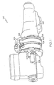
- FIG. 1 illustrates an exemplary embodiment of a driveline system that includes a wound field generator installed in the driveline system
- FIG. 2 is an example of an electrical schematic for a wound field generator in accordance with exemplary embodiments
- FIG. 3 depicts a cut-away view of an exemplary embodiment of a wound field generator with nested exciter and main generator stages
- FIG. 4 depicts a process for producing a wound field generator with nested exciter and main generator stages.
- FIG. 1 illustrates an exemplary embodiment of a driveline system 100.
- the driveline system 100 is part of a land-based vehicle driveline, such as a truck or a tank.
- the driveline system 100 includes a wound field generator 102 inserted between an engine 104 and a transmission 106.
- the wound field generator 102 has coupling points 108 that align with existing coupling points on the engine 104 and transmission 106.
- the impact on existing components, such as the engine 104 and transmission 106 can be minimized when the wound field generator 102 is inserted into the driveline system 100.
- wound field generator 102 is depicted between the engine 104 and transmission 106, it will be understood that the arrangement of components on the driveline system 100 is not so limited. For instance, there may be additional components, such as a clutch inserted in the driveline system 100, or the wound field generator 102 may be coupled to the opposite end of the transmission 106 if a smaller diameter is desired for the wound field generator 102.
- FIG. 2 depicts an example of an electrical schematic 200 for the wound field generator 102 of FIG. 1 .
- the electrical schematic 200 includes an exciter coil 202 that establishes a direct current (DC) field.
- the exciter coil 202 may receive DC power from a DC supply, such as a battery or an alternator (not depicted).
- the exciter coil 202 can be implemented as an exciter stator, with conductive coils wrapped around an iron core.
- An exciter armature 204 receives an induced current from the DC field established by the exciter coil 202.
- the exciter armature 204 generates an alternating current (AC) as part of a rotating assembly 206 upon rotation through the DC field.
- AC alternating current
- the rotating assembly 206 also includes a rotating rectifier assembly 208 that converts the AC generated by the exciter armature 204 to DC.
- the AC-to-DC conversion may be performed using multiple diodes.
- a rotor coil 210 is coupled to the rotating rectifier assembly 208 to establish a main rotating DC field.
- the rotor coil 210 is part of a main stage rotor, which includes conductive coils wrapped around an iron core to establish the main rotating DC field.
- Main stage output coils 212 generate AC induced from the main rotating DC field of the rotor coil 210 as the rotor coil 210 rotates in proximity of the main stage output coils 212.
- the main stage output coils 212 are part of a main stage stator of a wound field generator, which include conductive coils wrapped around an iron core.
- a current transformer 214 may be used to extract current from the main stage output coils 212 for test purposes or to provide AC power for other uses. Additional access points, such as access point 216 and access point 218, may also be used for testing or other purposes.
- AC generated by the main stage output coils 212 can be routed to an output rectifier assembly 220 to perform AC-to-DC conversion.
- the AC-to-DC conversion may be performed using multiple diodes for rectification.
- Junction point 222 and junction point 224 provide access to high voltage DC that is output from the output rectifier assembly 220.
- An electromagnetic interference (EMI) filter 226 may be connected between junction point 222 and junction point 224 to filter EMI effects, such as high frequency noise.
- the components in FIG. 2 can be repeated multiple times and in varying scale to fit a number of geometries and power needs. For example, multiple coils can be distributed circumferentially about a central axis. The components of FIG. 2 can also be further partitioned into groups distributed between multiple physical locations. For instance, the output rectifier assembly 220 can be located remotely from the main stage output coils 212.
- FIG. 3 depicts a cut-away view of an exemplary embodiment of the wound field generator 102 of FIG. 1 .
- the wound field generator 102 of FIG. 3 includes a main stage stator 302 and a main stage rotor 304, which may be collectively referred to as main generator stage 305.
- a rotating rectifier assembly 306 can be used electrically to connect the main generator stage 305 with a nested exciter stage 307, which includes an exciter stage stator 308 and an exciter stage rotor 310.
- the main stage rotor 304 and the exciter stage rotor 310 are coupled to a rotor member 312, which is driven by the rotation of driveshaft 314.
- the driveshaft 314 rotates about a central axis 316 of the wound field generator 102, causing the rotor member 312 to rotate.
- the main stage stator 302 and exciter stage stator 308 remain stationary as the rotor member 312 rotates.
- the rotating rectifier assembly 306 may be located in close proximity to the main stage rotor 304 or the exciter stage rotor 310 on the rotor member 312, and electrically coupled to both the main stage rotor 304 and the exciter stage rotor 310.
- a wire cover 318 may be used to hold wiring in support of the rotating rectifier assembly 306.
- the main stage stator 302 provides the electrical characteristics of the main stage output coils 212 of FIG. 2 .
- the main stage rotor 304 may be electrically equivalent to the rotor coil 210 of FIG. 2 .
- the rotating rectifier assembly 306 may be electrically equivalent to the rotating rectifier assembly 208 of FIG. 2 .
- the exciter stage stator 308 may be electrically equivalent to the exciter coil 202, and the exciter stage rotor 310 may be electrically equivalent to the exciter armature 204 of FIG. 2 .
- the alternating current in the exciter stage rotor 310 flows through the rotating rectifier assembly 306 to produce a direct current in the main stage rotor 304.
- the direct current in the main stage rotor 304 creates a DC field to establish field communication inducing an alternating current in the main stage stator 302 as the rotor member 312 rotates.
- the AC in the main stage stator 302 can be converted to DC via an external output rectifier assembly, such as the output rectifier assembly 222 of FIG. 2 .
- AC power from the wound field generator 102 can also be used directly, for instance, in an AC distribution network.
- the wound field generator 102 can directly convert the mechanical rotation of the driveshaft 314 into a high-voltage DC power source and/or an AC power source.
- the main stage stator 302, main stage rotor 304, exciter stage stator 308, and exciter stage rotor 310 are arranged concentrically about the central axis 316, such that the exciter stage stator 308 and the exciter stage rotor 310 are radially nested about the central axis 316 of the wound field generator 102 with respect to the main stage stator 302 and the main stage rotor 304.
- This configuration results in minimal impact to the overall length of the driveline system 100 of FIG. 1 when the wound field generator 102 is inserted between the engine 104 and the transmission 106 and attached at coupling points 108.
- Driveline displacement 326 represents the addition in driveline length attributable to the wound field generator 102.
- the driveline displacement 326 is less than 100 millimeters to install a version of the wound field generator 102 weighing approximately 64 kilograms and generating approximately 100 kilowatts of electrical power. It will be understood that a wide variety of sizes can be implemented within the scope of the invention.
- the sequence in which the nested rotors and stators are spaced extending from the driveshaft 314 can vary within the scope of the invention.
- the radial distance between the exciter stage rotor 310 and the central axis 316 may be less than the radial distance between the exciter stage stator 308 and the central axis 316 as depicted in FIG. 3 .
- the radial distance between the exciter stage rotor 310 and the central axis 316 can be greater than the radial distance between the exciter stage stator 308 and the central axis 316, for instance, reversing the relative position of the exciter stage stator 308 and the exciter stage rotor 310 depicted in FIG. 3 .
- the radial distance between the main stage rotor 304 and the central axis 316 can be less than the radial distance between the main stage stator 302 and the central axis 316 as depicted in FIG. 3 .
- the radial distance between the main stage rotor 304 and the central axis 316 may be greater than the radial distance between the main stage stator 302 and the central axis 316.
- the relative positions of the main generator stage 305 and the nested exciter stage 307 can be reversed such that the radial distance between the main generator stage 305 and the central axis 316 is less than the radial distance between the nested exciter stage 307 and the central axis 316.
- the driveshaft 314 may also be coupled to components of the engine 104 and transmission 106.
- the driveshaft 314 is coupled to engine component 320 in FIG. 3 , which may be a flywheel or other rotating component.
- the wound field generator 102 of FIG. 3 may also include other components to support operation of the wound field generator 102.
- a coolant pump 322 can be used to circulate a coolant and/or lubricant from a reservoir 324 up to various components of the wound field generator 102.
- a plurality of bearings such as bearings 326 and 328 may be used to support rotation within the wound field generator 102.
- the bearings 326 and 328 enable the wound field generator 102 to be self-supporting.
- a crankshaft in the engine 104 of FIG. 1 is directly coupled to the rotor member 312, where the rotor member 312 acts as a flywheel for the engine 104.
- bearings 326 and 328 can be omitted, as crankshaft bearings in the engine 104 may be sufficient to support rotation of the rotor member 312.
- the main stage stator 302 and the exciter stage stator 308 can be directly coupled to the engine 104.
- FIG. 4 depicts a process 400 for nesting exciter and main generator stages in a wound field generator, such as the wound field generators 102 of FIGs. 1 and 3 .
- exciter stage rotor 310 is coupled to rotor member 312 in the wound field generator 102.
- main stage rotor 304 is coupled to rotor member 312.
- rotating rectifier assembly 306 is electrically coupled to exciter stage rotor 310 and main stage rotor 304.
- exciter stage stator 308 is arranged to establish field communication with exciter stage rotor 310 in the wound field generator 102.
- main stage stator 302 is arranged to establish field communication with the main stage rotor 304 in the wound field generator 102.
- exciter stage stator 308 and exciter stage rotor 310 are radially nested about central axis 316 of the wound field generator 102 with respect to main stage stator 302 and main stage rotor 304.
- the wound field generator 102 produced via process 400 of FIG. 4 can be connected inline on driveline system 100 via coupling points 108, for instance, to couple the wound field generator 102 to engine 104 and a transmission 106.
- the engine 104, wound field generator 102, and transmission 106 may be driven by driveshaft 314 of FIG. 3 .
- Various arrangements of the exciter stage rotor 310, exciter stage stator 308, main stage rotor 304, and main stage stator 302 can be used to place components closer or further from the central axis 316. Keeping components with a higher mass closer to the central axis 316 may affect the moment of inertia and other design/performance parameters of the wound field generator 102.
- a driveline installable wound field generator with nested exciter and main generator stages to generate electrical power.
- Nesting exciter and main generator stages of the wound field generator results in a compact design that removes mechanical inefficiencies of pulley, gear, or chain drive systems.
- Nesting the wound field generator stages can also reduce driveline length as compared to cascaded generator stages along the driveline and/or use of a permanent magnet rotor.
- Using a wound field generator may lower overall system weight and cost as active rectification can be avoided, which may otherwise be employed in a permanent magnet system. If an inverter is used, the wound field generator can also be used as an integrated starter generator.
Landscapes
- Engineering & Computer Science (AREA)
- Power Engineering (AREA)
- Synchronous Machinery (AREA)
- Connection Of Motors, Electrical Generators, Mechanical Devices, And The Like (AREA)
- Hybrid Electric Vehicles (AREA)
- Manufacture Of Motors, Generators (AREA)
Applications Claiming Priority (1)
| Application Number | Priority Date | Filing Date | Title |
|---|---|---|---|
| US12/499,292 US20110006545A1 (en) | 2009-07-08 | 2009-07-08 | Nested exciter and main generator stages for a wound field generator |
Publications (2)
| Publication Number | Publication Date |
|---|---|
| EP2273656A2 true EP2273656A2 (de) | 2011-01-12 |
| EP2273656A3 EP2273656A3 (de) | 2013-10-23 |
Family
ID=43033219
Family Applications (1)
| Application Number | Title | Priority Date | Filing Date |
|---|---|---|---|
| EP10251222.5A Withdrawn EP2273656A3 (de) | 2009-07-08 | 2010-07-08 | Integrierte Erreger und Hauptgeneratorstufen für einen gewickelten Feldgenerator |
Country Status (7)
| Country | Link |
|---|---|
| US (1) | US20110006545A1 (de) |
| EP (1) | EP2273656A3 (de) |
| JP (1) | JP2011019391A (de) |
| KR (1) | KR101182493B1 (de) |
| CN (1) | CN101951062A (de) |
| IL (1) | IL206908A0 (de) |
| ZA (1) | ZA201004831B (de) |
Cited By (3)
| Publication number | Priority date | Publication date | Assignee | Title |
|---|---|---|---|---|
| GB2496674A (en) * | 2011-11-18 | 2013-05-22 | Cummins Generator Technologies | Apparatus for providing excitation to a rotating electrical machine |
| EP3113341A3 (de) * | 2015-06-08 | 2017-04-19 | Kohler Co. | Wechselstromgenerator mit doppeltem lufstpalt |
| ITUA20163299A1 (it) * | 2016-05-10 | 2017-11-10 | Idm Srl | Alternatore multipolare perfezionato |
Families Citing this family (18)
| Publication number | Priority date | Publication date | Assignee | Title |
|---|---|---|---|---|
| US8207644B2 (en) * | 2009-07-14 | 2012-06-26 | Hamilton Sundstrand Corporation | Hybrid cascading lubrication and cooling system |
| US20110241465A1 (en) * | 2010-03-30 | 2011-10-06 | Honeywell International Inc. | Low profile starter-generator |
| JP5626085B2 (ja) * | 2011-04-12 | 2014-11-19 | コベルコ建機株式会社 | ハイブリッド建設機械 |
| KR101316602B1 (ko) * | 2013-07-11 | 2013-10-18 | 주식회사 맥시스 | 차량의 엔진 직결형 발전 장치의 변속기측 커플링 장치 |
| KR101316601B1 (ko) * | 2013-07-11 | 2013-10-18 | 주식회사 맥시스 | 차량의 엔진 직결형 발전 장치의 엔진측 커플링 장치 |
| KR101322358B1 (ko) * | 2013-07-11 | 2013-10-28 | 주식회사 맥시스 | 차량의 엔진 직결형 발전 장치 |
| CN104047421B (zh) * | 2014-05-27 | 2016-03-23 | 中国十七冶集团有限公司 | 成品组装式塑料组合周转模板施工方法 |
| JP6359116B2 (ja) * | 2014-11-10 | 2018-07-18 | 三菱電機株式会社 | 回転電機 |
| CN106505812A (zh) * | 2015-09-08 | 2017-03-15 | 博格华纳公司 | 嵌套式双电机/发电机 |
| US9765850B2 (en) * | 2015-10-13 | 2017-09-19 | Goodrich Corporation | Saturation-controlled variable damper systems and methods |
| US9732818B2 (en) | 2015-10-13 | 2017-08-15 | Goodrich Corporation | Axial engagement-controlled variable damper systems and methods |
| US10778123B2 (en) | 2015-10-16 | 2020-09-15 | Kohler Co. | Synchronous inverter |
| US10148207B2 (en) * | 2015-10-16 | 2018-12-04 | Kohler Co. | Segmented waveform converter on controlled field variable speed generator |
| US10148202B2 (en) | 2015-10-16 | 2018-12-04 | Kohler Co. | Hybrid device with segmented waveform converter |
| US10063097B2 (en) | 2015-10-16 | 2018-08-28 | Kohler Co. | Segmented waveform converter on controlled field variable speed generator |
| JP6450735B2 (ja) * | 2016-11-30 | 2019-01-09 | 西芝電機株式会社 | 励磁機固定子の設置構造、及び回転電機 |
| JP7274135B2 (ja) * | 2019-07-18 | 2023-05-16 | 学校法人法政大学 | 回転機システム |
| KR102547853B1 (ko) * | 2021-05-27 | 2023-06-27 | 에이치디현대일렉트릭 주식회사 | 발전기의 여자기용 정류장치 |
Family Cites Families (47)
| Publication number | Priority date | Publication date | Assignee | Title |
|---|---|---|---|---|
| US3676764A (en) * | 1971-01-29 | 1972-07-11 | Kohler Co | Brushless alternating current generator |
| DE2543196A1 (de) * | 1975-09-27 | 1977-04-07 | Bosch Gmbh Robert | Schleifringlose elektrische maschine |
| BE834293A (fr) * | 1975-10-08 | 1976-04-08 | Acec | Machine dynamoelectrique double |
| JPS5668241A (en) * | 1979-11-08 | 1981-06-08 | Toshiba Corp | Brushless synchronous machine |
| JPS6334456Y2 (de) * | 1981-02-28 | 1988-09-13 | ||
| US4887020A (en) * | 1984-07-23 | 1989-12-12 | U.S. Philips Corporation | Self-compensating brushless alternator |
| US4684873A (en) * | 1985-09-25 | 1987-08-04 | Sundstrand Corporation | Hybrid generating system |
| JPS6281956A (ja) * | 1985-10-04 | 1987-04-15 | Fuji Electric Co Ltd | ブラシレス同期機 |
| JPS62207157A (ja) * | 1986-03-05 | 1987-09-11 | Fuji Electric Co Ltd | ブラシレス同期機 |
| DE19504847B4 (de) * | 1994-02-23 | 2006-04-27 | Luk Gs Verwaltungs Kg | Überwachungsverfahren für ein Drehmoment-Übertragungssystem eines Kraftfahrzeugs |
| JPH0946990A (ja) * | 1995-08-02 | 1997-02-14 | Meidensha Corp | ブラシレス発電機の励磁構造 |
| US6191185B1 (en) * | 1995-09-18 | 2001-02-20 | Spalding Sports Worldwide, Inc. | UV curable ink containing aluminum trihydroxide for use in pad printing, and method of printing |
| DE29717416U1 (de) * | 1997-09-30 | 1999-02-04 | Robert Bosch Gmbh, 70469 Stuttgart | Elektrische Maschine, insbesondere schleifringloser Drehstrom-Generator |
| US6191510B1 (en) * | 1997-12-19 | 2001-02-20 | 3M Innovative Properties Company | Internally damped stator, rotor, and transformer and a method of making |
| US6064121A (en) * | 1998-02-27 | 2000-05-16 | Hamilton Sundstrand Corporation | Axially compact generator set and refrigeration system employing the same |
| JP4196433B2 (ja) | 1998-07-09 | 2008-12-17 | 日本精工株式会社 | 密閉型アクチュエータ |
| US6465928B1 (en) * | 1998-12-23 | 2002-10-15 | Hamilton Sundstrand Corporation | Multi-pole generator rotor and method of making the same |
| US6174254B1 (en) * | 1998-12-30 | 2001-01-16 | Hamilton Sundstrand Corporation | Continuously variable transmission with control arrangement and for reducing transmission belt slippage |
| US6332204B1 (en) * | 1999-03-31 | 2001-12-18 | International Business Machines Corporation | Recovering and relocating unreliable disk sectors when encountering disk drive read errors |
| US6290620B1 (en) * | 1999-06-25 | 2001-09-18 | Hamilton Sundstrand Corporation | Continuously variable transmission with control arrangement and method for reducing impact of shock load |
| US6727609B2 (en) * | 2001-08-08 | 2004-04-27 | Hamilton Sundstrand Corporation | Cooling of a rotor for a rotary electric machine |
| US6628005B2 (en) * | 2001-09-27 | 2003-09-30 | Siemens Westinghouse Power Corporation | Single speed turbine generator for different power system output frequencies in power generation systems and associated methods |
| DE20220455U1 (de) * | 2001-11-15 | 2003-09-04 | Karl Heinz Linnig GmbH & Co. KG, 88677 Markdorf | Vorrichtung zur Dämpfung von Drehschwingungen |
| JP3661634B2 (ja) * | 2001-11-27 | 2005-06-15 | 株式会社デンソー | 両面空隙型回転電機 |
| JP4000863B2 (ja) * | 2002-02-15 | 2007-10-31 | 株式会社デンソー | 車両用発電システム |
| US20040000820A1 (en) * | 2002-06-13 | 2004-01-01 | Cromas Joseph Charles | Automotive generator |
| FR2844856B1 (fr) * | 2002-09-24 | 2005-12-30 | Valeo Embrayages | Filtre pour transmission a changement de rapport automatise, continu ou non, notamment pour vehicule automobile |
| US7230363B2 (en) * | 2004-03-30 | 2007-06-12 | Honeywell International, Inc. | Low profile generator configuration |
| US7154193B2 (en) * | 2004-09-27 | 2006-12-26 | General Electric Company | Electrical machine with double-sided stator |
| JP4254658B2 (ja) * | 2004-08-23 | 2009-04-15 | 株式会社デンソー | 車載電源システム |
| JP4677806B2 (ja) * | 2005-03-25 | 2011-04-27 | 株式会社日立製作所 | 発電機及び発電システム |
| US7511392B2 (en) * | 2005-06-17 | 2009-03-31 | Hamilton Sundstrand Corporation | Rotating rectifier module |
| KR100669164B1 (ko) | 2005-10-10 | 2007-01-16 | 백정호 | 하이브리드 자동차를 위한 수동변속기 장착용 동력모터와일체로 형성된 전자석 클러치 |
| US7586224B2 (en) * | 2005-11-16 | 2009-09-08 | Hamilton Sundstrand Corporation | Rotating rectifier assembly |
| US7389712B2 (en) * | 2005-11-21 | 2008-06-24 | Hamilton Sundstrand Corporation | Bi-directional two mode input, uni-directional single mode output drive train |
| FR2895973A3 (fr) * | 2006-01-10 | 2007-07-13 | Philippe Luca | Generateur intercale pour moteur marin inboard |
| US7385332B2 (en) * | 2006-04-17 | 2008-06-10 | Hamilton Sundstrand Corporation | Permanent magnet dynamoelectric machine with axially displaceable permanent magnet rotor assembly |
| US7268522B1 (en) * | 2006-05-20 | 2007-09-11 | Hamilton Sundstrand Corporation | Excitation control for wound field synchronous dynamoelectric machines |
| WO2008005169A2 (en) * | 2006-06-14 | 2008-01-10 | Board Of Regents, The University Of Texas System | High performance rotating rectifier for ac generator exciters and related methods |
| KR100678492B1 (ko) | 2006-10-23 | 2007-02-02 | 주식회사 대흥기전 | 여자기의 계자를 영구자석 복합방식으로 한 회전계자형자여자식 동기발전기 |
| US7573145B2 (en) * | 2006-11-16 | 2009-08-11 | Cummins Power Generation Ip, Inc. | Electric power generation system controlled to reduce perception of operational changes |
| US7642684B2 (en) * | 2007-02-15 | 2010-01-05 | Hamilton Sunstrand Corporation | Nested variable field dynamoelectric machine |
| US7728475B2 (en) * | 2007-02-20 | 2010-06-01 | Hamilton Sundstrand Corporation | Thermally operated rotatable component restraint system |
| US7514806B2 (en) * | 2007-06-05 | 2009-04-07 | Honeywell International Inc. | Engine start system with quadrature AC excitation |
| US7728477B2 (en) * | 2008-01-17 | 2010-06-01 | Honeywell International Inc. | Dual purpose permanent magnet exciter |
| US7915869B2 (en) * | 2008-04-01 | 2011-03-29 | Honeywell International Inc. | Single stage starter/generator with rotor quadrature AC excitation |
| CN201312220Y (zh) * | 2008-11-27 | 2009-09-16 | 湘潭电机股份有限公司 | 一种旋转励磁机采用外转子式的无刷同步发电机 |
-
2009
- 2009-07-08 US US12/499,292 patent/US20110006545A1/en not_active Abandoned
-
2010
- 2010-06-24 KR KR1020100059981A patent/KR101182493B1/ko not_active Expired - Fee Related
- 2010-07-07 JP JP2010154400A patent/JP2011019391A/ja not_active Ceased
- 2010-07-07 CN CN2010102250520A patent/CN101951062A/zh active Pending
- 2010-07-08 IL IL206908A patent/IL206908A0/en unknown
- 2010-07-08 EP EP10251222.5A patent/EP2273656A3/de not_active Withdrawn
- 2010-07-08 ZA ZA2010/04831A patent/ZA201004831B/en unknown
Non-Patent Citations (1)
| Title |
|---|
| None |
Cited By (7)
| Publication number | Priority date | Publication date | Assignee | Title |
|---|---|---|---|---|
| GB2496674A (en) * | 2011-11-18 | 2013-05-22 | Cummins Generator Technologies | Apparatus for providing excitation to a rotating electrical machine |
| GB2496674B (en) * | 2011-11-18 | 2018-05-09 | Cummins Generator Technologies | Apparatus for providing excitation to a rotating electrical machine |
| EP3113341A3 (de) * | 2015-06-08 | 2017-04-19 | Kohler Co. | Wechselstromgenerator mit doppeltem lufstpalt |
| US10273876B2 (en) | 2015-06-08 | 2019-04-30 | Kohler Co. | Dual axis alternator |
| US11286848B2 (en) | 2015-06-08 | 2022-03-29 | Kohler Co. | Dual axis alternator |
| US11905878B2 (en) | 2015-06-08 | 2024-02-20 | Kohler Co. | Dual axis alternator |
| ITUA20163299A1 (it) * | 2016-05-10 | 2017-11-10 | Idm Srl | Alternatore multipolare perfezionato |
Also Published As
| Publication number | Publication date |
|---|---|
| CN101951062A (zh) | 2011-01-19 |
| US20110006545A1 (en) | 2011-01-13 |
| ZA201004831B (en) | 2011-03-30 |
| EP2273656A3 (de) | 2013-10-23 |
| KR20110004777A (ko) | 2011-01-14 |
| KR101182493B1 (ko) | 2012-09-12 |
| JP2011019391A (ja) | 2011-01-27 |
| IL206908A0 (en) | 2010-12-30 |
Similar Documents
| Publication | Publication Date | Title |
|---|---|---|
| EP2273656A2 (de) | Integrierte Erreger und Hauptgeneratorstufen für einen gewickelten Feldgenerator | |
| US7095126B2 (en) | Internal energy generating power source | |
| US7230363B2 (en) | Low profile generator configuration | |
| US8207644B2 (en) | Hybrid cascading lubrication and cooling system | |
| US6707205B2 (en) | High-speed, high-power rotary electrodynamic machine with dual rotors | |
| US9935532B2 (en) | Double-rotor type electrical rotating machines | |
| US20100320860A1 (en) | Crowned end winding support for main wound field of a generator | |
| EP2985422B1 (de) | Starter-generatormodule für gasturbinenmotoren | |
| Stuebig et al. | Electromagnetic design of a 10 MW permanent magnet synchronous generator for wind turbine application | |
| US20100109471A1 (en) | Stator for a multiple phase rotary electric machine, multiple phase rotary electric machine including such rotor, and method for making such rotor | |
| KR101694099B1 (ko) | 복합 발전기 | |
| JPH1198786A (ja) | 車両用交流発電機 | |
| US9800122B2 (en) | Methods for handling a bearingless machine | |
| CN103051086A (zh) | 一种混合励磁式高效节能汽车交流发电机 | |
| KR101084354B1 (ko) | 제동권선이 내장된 교류발전기의 로우터 | |
| US10027210B2 (en) | Dual-output generators | |
| HK1148872A (en) | Nested exciter and main generator stages for a wound field generator | |
| Reiter et al. | Salient pole generators for belt-driven automotive alternator applications | |
| US20080067883A1 (en) | Generator and/or motor assembly | |
| US8963510B1 (en) | Acyclic exciter for an alternator | |
| WO2016072834A2 (en) | Energy convertor | |
| Zharkov et al. | An Electric Machine Integrated on the Shaft of the High-Pressure Compressor of a Gas Turbine Engine | |
| LIKE | Messages-723300141 | |
| LIKE | Topics-723300141 | |
| EP2690762A1 (de) | Erregerstromleitung für eine dynamoelektrische Maschine, und dynamoelektrische Maschine |
Legal Events
| Date | Code | Title | Description |
|---|---|---|---|
| PUAI | Public reference made under article 153(3) epc to a published international application that has entered the european phase |
Free format text: ORIGINAL CODE: 0009012 |
|
| AK | Designated contracting states |
Kind code of ref document: A2 Designated state(s): AL AT BE BG CH CY CZ DE DK EE ES FI FR GB GR HR HU IE IS IT LI LT LU LV MC MK MT NL NO PL PT RO SE SI SK SM TR |
|
| AX | Request for extension of the european patent |
Extension state: BA ME RS |
|
| PUAL | Search report despatched |
Free format text: ORIGINAL CODE: 0009013 |
|
| AK | Designated contracting states |
Kind code of ref document: A3 Designated state(s): AL AT BE BG CH CY CZ DE DK EE ES FI FR GB GR HR HU IE IS IT LI LT LU LV MC MK MT NL NO PL PT RO SE SI SK SM TR |
|
| AX | Request for extension of the european patent |
Extension state: BA ME RS |
|
| RIC1 | Information provided on ipc code assigned before grant |
Ipc: H02K 19/38 20060101ALI20130916BHEP Ipc: H02K 19/26 20060101ALI20130916BHEP Ipc: H02K 7/20 20060101ALI20130916BHEP Ipc: H02K 7/00 20060101AFI20130916BHEP |
|
| STAA | Information on the status of an ep patent application or granted ep patent |
Free format text: STATUS: THE APPLICATION IS DEEMED TO BE WITHDRAWN |
|
| 18D | Application deemed to be withdrawn |
Effective date: 20140424 |