EP2273857A1 - Vorrichtung zum Formen oder Bearbeiten von Werkstücken - Google Patents
Vorrichtung zum Formen oder Bearbeiten von Werkstücken Download PDFInfo
- Publication number
- EP2273857A1 EP2273857A1 EP20100450105 EP10450105A EP2273857A1 EP 2273857 A1 EP2273857 A1 EP 2273857A1 EP 20100450105 EP20100450105 EP 20100450105 EP 10450105 A EP10450105 A EP 10450105A EP 2273857 A1 EP2273857 A1 EP 2273857A1
- Authority
- EP
- European Patent Office
- Prior art keywords
- base frame
- processing module
- fiber composite
- plastic
- fibers
- Prior art date
- Legal status (The legal status is an assumption and is not a legal conclusion. Google has not performed a legal analysis and makes no representation as to the accuracy of the status listed.)
- Granted
Links
- 238000003754 machining Methods 0.000 title claims description 20
- 239000000835 fiber Substances 0.000 claims abstract description 49
- 239000004033 plastic Substances 0.000 claims abstract description 35
- 229920003023 plastic Polymers 0.000 claims abstract description 35
- 239000002131 composite material Substances 0.000 claims abstract description 28
- 239000011159 matrix material Substances 0.000 claims abstract description 11
- 229920000049 Carbon (fiber) Polymers 0.000 claims abstract description 8
- 229920002430 Fibre-reinforced plastic Polymers 0.000 claims abstract description 8
- 239000011151 fibre-reinforced plastic Substances 0.000 claims abstract description 8
- 239000003822 epoxy resin Substances 0.000 claims abstract description 6
- 229920000647 polyepoxide Polymers 0.000 claims abstract description 6
- 239000004917 carbon fiber Substances 0.000 claims abstract description 5
- 229920001169 thermoplastic Polymers 0.000 claims abstract description 4
- 239000004416 thermosoftening plastic Substances 0.000 claims abstract description 4
- 238000004080 punching Methods 0.000 claims description 21
- 238000005452 bending Methods 0.000 claims description 7
- 238000010276 construction Methods 0.000 claims description 6
- 229920001187 thermosetting polymer Polymers 0.000 claims description 6
- 239000012783 reinforcing fiber Substances 0.000 claims description 4
- 239000004744 fabric Substances 0.000 claims description 3
- 238000003825 pressing Methods 0.000 claims description 3
- 239000004918 carbon fiber reinforced polymer Substances 0.000 claims description 2
- 238000004049 embossing Methods 0.000 claims description 2
- 239000011888 foil Substances 0.000 claims description 2
- 238000007493 shaping process Methods 0.000 claims description 2
- 239000007787 solid Substances 0.000 claims description 2
- 230000002787 reinforcement Effects 0.000 abstract 1
- 239000000463 material Substances 0.000 description 12
- 230000000694 effects Effects 0.000 description 4
- 239000002699 waste material Substances 0.000 description 4
- 238000004519 manufacturing process Methods 0.000 description 3
- VNWKTOKETHGBQD-UHFFFAOYSA-N methane Chemical compound C VNWKTOKETHGBQD-UHFFFAOYSA-N 0.000 description 3
- 229910000831 Steel Inorganic materials 0.000 description 2
- 229910052782 aluminium Inorganic materials 0.000 description 2
- XAGFODPZIPBFFR-UHFFFAOYSA-N aluminium Chemical compound [Al] XAGFODPZIPBFFR-UHFFFAOYSA-N 0.000 description 2
- 238000013016 damping Methods 0.000 description 2
- 238000006073 displacement reaction Methods 0.000 description 2
- 230000005484 gravity Effects 0.000 description 2
- 239000010959 steel Substances 0.000 description 2
- 229910001060 Gray iron Inorganic materials 0.000 description 1
- 230000005540 biological transmission Effects 0.000 description 1
- 230000015572 biosynthetic process Effects 0.000 description 1
- 239000000969 carrier Substances 0.000 description 1
- 239000012876 carrier material Substances 0.000 description 1
- 238000010438 heat treatment Methods 0.000 description 1
- 239000010720 hydraulic oil Substances 0.000 description 1
- 229910052751 metal Inorganic materials 0.000 description 1
- 239000002184 metal Substances 0.000 description 1
- 238000000034 method Methods 0.000 description 1
- 238000003860 storage Methods 0.000 description 1
- 230000001629 suppression Effects 0.000 description 1
- 239000013585 weight reducing agent Substances 0.000 description 1
Images


Classifications
-
- B—PERFORMING OPERATIONS; TRANSPORTING
- B26—HAND CUTTING TOOLS; CUTTING; SEVERING
- B26F—PERFORATING; PUNCHING; CUTTING-OUT; STAMPING-OUT; SEVERING BY MEANS OTHER THAN CUTTING
- B26F1/00—Perforating; Punching; Cutting-out; Stamping-out; Apparatus therefor
- B26F1/02—Perforating by punching, e.g. with relatively-reciprocating punch and bed
-
- B—PERFORMING OPERATIONS; TRANSPORTING
- B30—PRESSES
- B30B—PRESSES IN GENERAL
- B30B15/00—Details of, or accessories for, presses; Auxiliary measures in connection with pressing
- B30B15/04—Frames; Guides
-
- B—PERFORMING OPERATIONS; TRANSPORTING
- B30—PRESSES
- B30B—PRESSES IN GENERAL
- B30B15/00—Details of, or accessories for, presses; Auxiliary measures in connection with pressing
- B30B15/04—Frames; Guides
- B30B15/047—C-shaped frames
-
- H—ELECTRICITY
- H05—ELECTRIC TECHNIQUES NOT OTHERWISE PROVIDED FOR
- H05K—PRINTED CIRCUITS; CASINGS OR CONSTRUCTIONAL DETAILS OF ELECTRIC APPARATUS; MANUFACTURE OF ASSEMBLAGES OF ELECTRICAL COMPONENTS
- H05K3/00—Apparatus or processes for manufacturing printed circuits
- H05K3/0011—Working of insulating substrates or insulating layers
- H05K3/0044—Mechanical working of the substrate, e.g. drilling or punching
- H05K3/005—Punching of holes
Definitions
- the invention relates to a device for processing objects according to the preamble of claim 1.
- Devices according to the invention are used industrially, in particular for the production of perforated films.
- Punching devices are entirely made of metal, they consist in particular of aluminum, steel or gray cast iron. In the production of stamped or perforated films, it is necessary to comply with very small tolerances, for example in the range of 0.001 mm. Such a requirement also occurs, for example, in the production or perforation of printed circuit boards. At very high punching speeds of about 10 to 50 strokes per second, the entire punching device, in particular the punching tools as well as the machining module carrying the punching tools, are exposed to considerable thermal expansions. This in turn means that due to the thermal expansions the punching tools undergo a lateral offset relative to their basic position and the stamped objects or films have a deviating punching pattern after the heating of the punching device.
- the object of the invention is to provide a device which avoids the disadvantages described above. Specifically, the object of the invention is directed to increasing the life of such a device, in particular to reduce the susceptibility to vibration and the susceptibility to thermal effects.
- a device for shaping or processing workpieces in particular for punching foils, with a base frame and a tool for machining the workpiece that is displaceable relative to this base frame along a preferably linear path, in that the base frame is at least partially consists of fiber-reinforced plastic or fiber composite plastic.
- a preferred aspect of the invention is that the device has a processing module, which carries the tool, and is displaceably mounted along a, preferably linear, path.
- the construction of pressing and punching devices is made possible, in which a variety of tools can be operated together. It is advantageous that due to the low thermal bending and expansion, the relative positioning of the tools is subject to only slight fluctuations.
- Another preferred aspect of the invention is that the path along which the processing module is mounted is arranged horizontally or horizontally in the working position.
- the base frame is C-shaped and made of plastic or fiber composite plastic, wherein in the base frame at least one recess is provided which is penetrated by the tool which is displaceable in this recess along the way and one end of the path lies in the interior of the C-shaped base frame.
- An additional aspect of the invention is characterized in that the processing module consists at least partially of fiber-reinforced plastic or fiber composite plastic.
- Another aspect of the invention is characterized in that the processing module and / or the base frame entirely consist of fiber-reinforced plastic or fiber composite plastic.
- processing module and / or the base frame each have at least one solid plate made of fiber composite plastic.
- a preferred aspect of the invention is that the plate of the processing module is aligned parallel to the plate of the base frame.
- the invention relates to a device which is characterized in that each plate or the base frame or the processing module of a plurality of flat, in particular in sandwich construction, interconnected plate-shaped elements is constructed.
- the to form the fiber composite plastic has a thermoplastic or a thermosetting matrix, preferably of epoxy resin.
- the fiber composite plastic contains inorganic reinforcing fibers and / or organic reinforcing fibers, in particular carbon fibers or carbon fibers.
- Devices according to the invention are preferably characterized in that the fibers are present in the form of rovings, mats, fabrics or layers.
- This provides the necessary internal stability and improves the vibration behavior of the machining module and the base frame.
- a preferred aspect of the invention is characterized in that the fiber composite plastic is a carbon fiber reinforced plastic, wherein the fibers, preferably in multiple layers, are embedded in the plastic matrix and wherein the elastic modulus of the fibers is higher than the elastic modulus of the plastic matrix.
- This provides a particularly high rigidity and suppresses mechanical vibrations that are excited by the movements of the machining module.
- a preferred embodiment of the invention is characterized in that the fiber composite plastic short fibers with a length between 0.1 to 1 mm and / or long fibers with a length of about 80% to 150% of the maximum dimension of the base frame and the processing module.
- Plastics with fibers of this length are particularly suitable for the suppression of internal material vibrations.
- the invention relates to the advantageous aspect that the fiber composite plastic has a fiber content of 40 to 80% by weight.
- a preferred aspect of the invention provides that the processing module has recesses into which tools are inserted.
- the device according to the invention has tools for punching, bending, embossing, riveting or pressing.
- a first embodiment of the invention shown in FIG Fig. 1 , comprises a base frame 10, which is formed with a plate 1.
- the plate 1 On its underside, the plate 1 a Fastening device for fastening to a base frame 10.
- the plate 1 consists of a number of flat sheet-bonded flat plate elements, which are joined together in sandwich construction.
- the plate 1 On its upper side, the plate 1 has four holes, which are penetrated by guide columns 3.
- guide columns 3 On each side of the plate 1 two guide columns 3 are arranged in each case. In the intermediate region between the guide columns 3 are guide and support parts for the objects to be punched or for a film.
- a processing module 2 Opposite the base frame 10, a processing module 2 is mounted displaceably in parallel along a linear path.
- This processing module 2 comprises a further plate having four continuous recesses, which are penetrated by one of the guide columns 3.
- a holder 5 for tools 6 is arranged at the bottom of the machining module 2.
- This holder 5 is screwed to the processing module 2 or the processing module 2 and the holder 5 are formed from a single molded part.
- a number of tools 6 is arranged at the bottom or on the plate 1 of the frame 10 facing side of the machining module 2.
- the drive of the device according to the invention by means of cylinders 4, which are arranged in the central region of the machining module 2 and in the region of the guide rods 3. If the cylinders 4 are simultaneously subjected to compressed air or hydraulic oil, the processing module 2, the holder 5 for the tools 6 and the individual tools 6 are displaced along a linear path extending parallel to the extension direction of the guide columns 3 and the tools 6 punch a recess in the processing object.
- the plate of the processing module 2 is parallel to the plate of the base frame 10th
- the fiber composite plastic used for the formation of the plates of the processing module 2 and the base frame 10 has a fiber content of 40% by weight to 80% by weight and has a thermosetting or thermoplastic matrix system.
- the effect according to the invention can be achieved with a fiber composite plastic with rovings, with layers or with fabrics.
- thermosetting matrix system namely epoxy resin
- a carbon fabric with a quasi-isotropic structure wherein the resulting fiber composite plastic has a fiber content of 56% by weight.
- the present case measures the space diagonal of this plate 1 about 75cm.
- a further embodiment of the invention corresponds to the in Fig. 1 illustrated embodiment with the difference that the punching movements are carried out in the horizontal or horizontal direction.
- a punching movement in the horizontal direction due to the large weight of the mechanical components is not possible.
- the guide columns 3 and the base frame 10 and the processing module 2 are slightly bent, which reduces the ease of movement.
- a mechanical stress is induced by the thermal expansion of the material, which further complicates the displacement of the processing module 2 relative to the base frame 10 and the guide columns.
- thermosetting matrix system namely epoxy resin
- a carbon fabric with a quasi-isotropic structure wherein the resulting fiber composite plastic has a fiber content of 56% by weight.
- the present case measures the space diagonal of this plate 1 about 60cm.
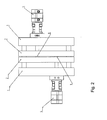
- a third embodiment which is in Fig. 2 is provided, provides a C-shaped base frame 10 made of fiber composite material.
- the workpiece to be machined from the side can be introduced and positioned with a positioning device, such as a robot.
- the tools are not firmly connected to the structure, but pass through a recess in the upper region of the base frame 2.
- the tools 6 are driven by a hydraulic or pneumatic cylinder 4, moved through the recess of the base frame 10 and act on the machined Workpiece.
- thermosetting matrix system namely epoxy resin
- the resulting fiber composite plastic has a fiber content of 56% by weight.
- the dimensions of the base frame 10 are about 50cm.
Landscapes
- Engineering & Computer Science (AREA)
- Mechanical Engineering (AREA)
- Life Sciences & Earth Sciences (AREA)
- Forests & Forestry (AREA)
- Manufacturing & Machinery (AREA)
- Microelectronics & Electronic Packaging (AREA)
- Machine Tool Units (AREA)
- Perforating, Stamping-Out Or Severing By Means Other Than Cutting (AREA)
- Processing And Handling Of Plastics And Other Materials For Molding In General (AREA)
- Casting Or Compression Moulding Of Plastics Or The Like (AREA)
Abstract
Description
- Die Erfindung betrifft eine Vorrichtung zum Bearbeiten von Gegenständen gemäß dem Oberbegriff des Anspruchs 1.
- Erfindungsgemäße Vorrichtungen werden insbesondere zur Fertigung von perforierten Folien gewerblich angewendet.
- Herkömmliche Bearbeitungsvorrichtungen wie z.B. Stanzvorrichtungen sind zur Gänze aus Metall aufgebaut, sie bestehen insbesondere aus Aluminium, Stahl oder Grauguss. Bei der Herstellung von gestanzten bzw. perforierten Folien ist es erforderlich, äußerst geringe Toleranzen, etwa im Bereich von 0,001mm, einzuhalten. Eine derartige Anforderung tritt beispielsweise auch bei der Herstellung bzw. Lochung von gedruckten Leiterplatten auf. Bei sehr hohen Stanzgeschwindigkeiten von etwa 10 bis 50 Hüben pro Sekunde ist die gesamte Stanzvorrichtung, insbesondere die Stanzwerkzeuge sowie das die Stanzwerkzeuge tragende Bearbeitungsmodul, nicht unerheblichen thermischen Ausdehnungen ausgesetzt. Dies wiederum führt dazu, dass aufgrund der thermischen Ausdehnungen die Stanzwerkzeuge einen seitlichen Versatz gegenüber ihrer Grundposition erfahren und die gestanzten Gegenstände bzw. Folien nach der Erwärmung der Stanzvorrichtung ein abweichendes Stanzmuster aufweisen.
- Aus diesem Grund ist der Aufbau größerer Vorrichtungen, die Gegenstände mit Oberflächen von mehr als 10 cm2 Ausdehnung bearbeiten können, nicht möglich. Bei typischen Anlagen gemäß dem Stand der Technik wird so vorgegangen, dass für einzelne Teilbereiche bzw. Bearbeitungsprozesse ein eigenes Werkzeug verwendet wird und eine Vielzahl von Werkzeugen in einen großen gemeinsamen Werkzeugrahmen eingebaut wird. Es kann jedoch aufgrund der thermischen Ausdehnung weiterhin zu Bearbeitungs- oder Vorschubfehlern kommen.
- Zusätzlich besteht bei großen Werkzeugrahmen mit mehreren eingebauten Bearbeitungsmodulen oder Werkzeugträgern das Problem, dass der Werkzeugrahmen aufgrund seiner Ausdehnung und Beschaffenheit durch die Hubbewegungen in seiner Eigenschwingung angeregt wird und zusätzlichen schwingungsbedingten mechanischen Belastungen ausgesetzt ist, welche die Lebenszeit der Standzeit deutlich herabsetzen.
- Die Aufgabe der Erfindung liegt darin, eine Vorrichtung zur Verfügung zu stellen, welche die eingangs beschriebenen Nachteile vermeidet. Speziell ist die Aufgabe der Erfindung darauf gerichtet, die Lebensdauer einer solchen Vorrichtung zu erhöhen, insbesondere die Schwingungsanfälligkeit und die Anfälligkeit gegenüber thermischen Effekten zu verringern.
- Erfindungsgemäß werden diese Nachteile bei einer Vorrichtung zum Formen oder Bearbeiten von Werkstücken, insbesondere zum Stanzen von Folien, mit einem Grundgestell sowie einem gegenüber diesem Grundgestell entlang eines, vorzugsweise linearen, Wegs verschiebbar gelagerten Werkzeugs zur Bearbeitung des Werkstücks dadurch überwunden, dass das Grundgestell zumindest teilweise aus faserverstärktem Kunststoff bzw. Faserverbundkunststoff besteht.
- Hierdurch ergibt sich der erhebliche Vorteil, dass die gesamte Vorrichtung ein geringeres Gewicht aufweist und insbesondere weniger Energie zum Betrieb der Bearbeitungsvorrichtung benötigt wird. Ferner werden aufgrund des verwendeten Materials resonanzbedingte Durchbiegungen bei großen Spannweiten von Bearbeitungsmodulen vermieden. Aufgrund der beinahe verschwindenden Wärmeausdehnung des verwendeten Materials ist die Form der bearbeiteten Gegenstände unabhängig von der Temperatur. Ferner wird erfindungsgemäß eine erhöhte Materialabnutzung vermieden, da die Bearbeitungsvorrichtungen auch bei hohen Hubzahlen keinen mechanischen Schwingungen und keinen Resonanzphänomenen unterliegen. Selbst bei Temperaturerhöhungen, die aufgrund des Bearbeitungsprozesses unweigerlich als Reibungsabwärme auftreten, kann eine gleichmäßige Schnittspalte von weniger als 0,0015 mm pro Seite eingehalten werden.
- Durch die Vermeidung von mechanischen Spannungen, die von Schwingungen sowie von thermischer Ausdehnung herrühren, wird die Lebensdauer sämtlicher Komponenten der Vorrichtung, insbesondere der Werkzeuge, erzielt.
- Weitere vorteilhafte Ausgestaltungen und Aspekte der Erfindung werden in den Unteransprüchen beschrieben.
- Ein bevorzugter Aspekt der Erfindung besteht darin, dass die Vorrichtung ein Bearbeitungsmodul aufweist, welches das Werkzeug trägt, und entlang eines, vorzugsweise linearen, Wegs verschiebbar gelagert ist.
- Mit dieser bevorzugten Weiterbildung der Erfindung wird der Aufbau von Press- und Stanzvorrichtungen ermöglicht, bei der eine Vielzahl von Werkzeugen gemeinsam betätigt werden kann. Dabei ist von Vorteil, dass auf Grund der geringen thermischen Verbiegungen und Ausdehnungen die relative Positionierung der Werkzeuge nur geringen Schwankungen unterliegt.
- Ein weiterer bevorzugter Aspekt der Erfindung besteht darin, dass der Weg, entlang dessen das Bearbeitungsmodul gelagert ist, in Arbeitsstellung waagrecht bzw. horizontal angeordnet ist.
- Auf Grund des geringen Eigengewichts sowie der hohen Biegesteifigkeit und Schwingungsdämpfung der erfindungsgemäßen Komponenten wird eine Verbiegung der Materialien weitestgehend verhindert. Die Relativbewegung zwischen dem Grundgestell bzw. den Führungssäulen und dem Bearbeitungsmodul ist somit auch bei einer in Arbeitsstellung waagrechten Stanzrichtung ohne Einschränkungen möglich.
- Besonders vorteilhaft bei einer derartigen Vorrichtung ist, dass der im Zuge des Stanzens entstehende Abfall durch die Schwerkraft von selbst nach unten fällt und ein zusätzlicher Schritt des Beseitigens von Stanzabfällen entfallen kann.
- Ein besonders vorteilhafter Aspekt der Erfindung besteht darin, dass das Grundgestell C-förmig ausgebildet ist und aus Kunststoff bzw. Faserverbundkunststoff besteht, wobei im Grundgestell zumindest eine Ausnehmung vorgesehen ist, die von dem Werkzeug durchsetzt ist, das in dieser Ausnehmung entlang des Wegs verschiebbar ist und ein Ende des Wegs im Innenbereich des C-förmigen Grundgestells liegt.
- In diesem Fall wirken große Schwingungskräfte auf das Grundgestell ein, was bei einem Aufbau der erfindungsgemäßen Vorrichtung mit konventionellen Werkstoffen zu massiven Schwingungen führen würde. Bei Verwendung eines erfindungsgemäßen Faserverbundkunststoffs werden derartige Schwingungen wirksam verhindert.
- Ein zusätzlicher Aspekt der Erfindung ist dadurch gekennzeichnet, dass das Bearbeitungsmodul zumindest teilweise aus faserverstärktem Kunststoff bzw. Faserverbundkunststoff besteht.
- Dies verbessert das Verhalten der erfindungsgemäßen Vorrichtung bei thermischen Einwirkungen. Weiters wird die Anfälligkeit gegenüber Schwingungen verbessert.
- Ein weiterer Aspekt der Erfindung ist dadurch gekennzeichnet, dass das Bearbeitungsmodul und/oder das Grundgestell zur Gänze aus faserverstärktem Kunststoff bzw. Faserverbundkunststoff bestehen.
- Dies verringert zum einen mechanische Schwingungen im Grundgestell, was eine zusätzliche Energieersparnis bietet. Weiters kann das Gewicht der erfindungsgemäßen Bearbeitungsvorrichtung hierdurch weiter reduziert werden.
- Ein weiterer Aspekt der Erfindung besteht darin, dass das Bearbeitungsmodul und/oder das Grundgestell jeweils zumindest eine massive Platte aus Faserverbundkunststoff aufweisen.
- Dies verbessert die mechanische Stabilität und verringert die mechanischen Schwingungen im Grundgestell und im Bearbeitungsmodul.
- Ein bevorzugter Aspekt der Erfindung besteht darin, dass die Platte des Bearbeitungsmoduls zur Platte des Grundgestells parallel ausgerichtet ist.
- Dies ermöglicht ein besonders effizientes Bearbeiten und verringert den für die Materialbearbeitung benötigten Hub. Zudem kann eine Lagerung des Bearbeitungsmoduls gegenüber dem Grundgestell leichter bewerkstelligt werden.
- Ferner betrifft die Erfindung eine Vorrichtung, die sich dadurch kennzeichnet, dass jede Platte bzw. das Grundgestell oder das Bearbeitungsmodul aus mehreren flächig, insbesondere in Sandwich-Bauweise, miteinander verbundenen plattenförmigen Elementen aufgebaut ist.
- Dies verbessert die mechanische Stabilität und verringert die im Material auftretenden Schwingungen.
- Ein weiterer Aspekt der Erfindung besteht darin, dass der zur Bildung der Faserverbundkunststoff eine thermoplastische oder eine duroplastische Matrix, vorzugsweise aus Epoxidharz, besitzt.
- Diese Materialien eignen sich besonders gut zur Unterdrückung von Schwingungen und geben den Werkzeugen die erforderliche innere Stabilität während des Bearbeitungsvorgangs.
- Ein zusätzlicher bevorzugter Aspekt der Erfindung besteht darin, dass der Faserverbundkunststoff anorganische Verstärkungsfasern und/oder organische Verstärkungsfasern, insbesondere Kohlestofffasern bzw. Karbonfasern, enthält.
- Diese Fasern verbessern die innere Stabilität des Bearbeitungsmoduls und verringern den Werkzeugverschleiß durch die Reduktion der inneren Schwingungen der Werkzeuge.
- Erfindungsgemäße Vorrichtungen kennzeichnen sich bevorzugterweise dadurch, dass die Fasern in Form von Rovings, Matten, Geweben oder Gelegen vorliegen.
- Dies sorgt für die nötige innere Stabilität und verbessert das Schwingungsverhalten des Bearbeitungsmoduls und des Grundgestells.
- Ein bevorzugter Aspekt der Erfindung ist dadurch gekennzeichnet, dass der Faserverbundkunststoff ein kohlenstofffaserverstärkter Kunststoff ist, wobei die Fasern, vorzugsweise in mehreren Lagen, in die Kunststoffmatrix eingebettet sind und wobei das Elastizitätsmodul der Fasern höher ist, als das Elastizitätsmodul der Kunststoffmatrix.
- Dies bietet eine besonders hohe Steifigkeit und unterdrückt mechanische Schwingungen, die durch die Bewegungen des Bearbeitungsmoduls angeregt werden.
- Eine bevorzugte Ausführungsform der Erfindung kennzeichnet sich dadurch, dass der Faserverbundkunststoff Kurzfasern mit einer Länge zwischen 0,1 bis 1 mm und/oder Langfasern mit einer Länge von etwa 80% bis 150% der maximalen Abmessung des Grundgestells bzw. des Bearbeitungsmoduls.
- Kunststoffe mit Fasern dieser Länge eignen sich besonders gut für die Unterdrückung von inneren Materialschwingungen.
- Weiters betrifft die Erfindung den vorteilhaften Aspekt, dass der Faserverbundkunststoff einen Fasergehalt von 40 bis 80 Gew% aufweist.
- Dies ermöglicht eine sehr hohe Materialsteifigkeit, die sich vorteilhaft auf das Schwingungsverhalten der Vorrichtung, insbesondere des Bearbeitungsmoduls auswirkt.
- Ein bevorzugter Aspekt der Erfindung sieht vor, dass das Bearbeitungsmodul Ausnehmungen aufweist, in die Werkzeuge eingebracht sind.
- Dies ermöglicht die Verwendung einer Vielzahl unterschiedlicher Werkzeuge und verringert die Übertragung von Schwingungen auf das Bearbeitungsmodul. Durch die Gewichtsreduktion des Bearbeitungsmoduls durch die Verwendung von Platten kann mit demselben Energieaufwand eine höhere Taktzahl an Hubbewegungen erreicht werden.
- Ein weiterer vorteilhafter Aspekt dieser Erfindung liegt darin, dass erfindungsgemäße Vorrichtung Werkzeuge zum Stanzen, Biegen, Prägen, Nieten oder Pressen aufweist.
- Durch die schwingungsarme Ausführung kann eine Vielzahl von unterschiedlichen Werkzeugen mit geringem Verschleiß und hoher Präzision betrieben werden.
- Die Erfindung wird anhand von drei Beispielen in den folgenden Figuren exemplarisch und nicht einschränkend dargestellt.
-
Fig. 1 zeigt den Aufbau einer erfindungsgemäßen Stanzvorrichtung. -
Fig. 2 zeigt den Aufbau einer erfindungsgemäßen Stanzvorrichtung mit waagrechter Verschiebung des Werkzeugs. -
Fig. 3 zeigt den Aufbau einer alternativen Ausführungsform der Erfindung mit C-förmigem Grundgestell. - Eine erste Ausführungsform der Erfindung, dargestellt in
Fig. 1 , umfasst ein Grundgestell 10, das mit einer Platte 1 gebildet ist. An ihrer Unterseite weist die Platte 1 eine Befestigungsvorrichtung zum Befestigen an einem Grundgestell 10 auf. Die Platte 1 besteht aus einer Anzahl von miteinander flächig verklebten flachen Plattenelementen, die in Sandwich-Bauweise zusammengefügt sind. An ihrer Oberseite weist die Platte 1 vier Löcher auf, die von Führungssäulen 3 durchsetzt sind. Auf jeder Seite der Platte 1 sind jeweils zwei Führungssäulen 3 angeordnet. Im Zwischenbereich zwischen den Führungssäulen 3 befinden sich Führungs- und Halterungsteile für die zu stanzenden Gegenstände bzw. für eine Folie. Gegenüber dem Grundgestell 10 ist ein Bearbeitungsmodul 2 entlang eines linearen Wegs parallel verschiebbar gelagert. Dieses Bearbeitungsmodul 2 umfasst eine weitere Platte, die vier durchgängige Ausnehmungen aufweist, die von jeweils einer der Führungssäulen 3 durchsetzt sind. An der Unterseite des Bearbeitungsmoduls 2 ist eine Halterung 5 für Werkzeuge 6 angeordnet. Diese Halterung 5 ist mit dem Bearbeitungsmodul 2 verschraubt bzw. sind das Bearbeitungsmodul 2 und die Halterung 5 aus einem einzigen Formteil gebildet. An der Unterseite bzw. an der der Platte 1 des Gestells 10 zugewandten Seite des Bearbeitungsmoduls 2 ist eine Anzahl von Werkzeugen 6 angeordnet. - Der Antrieb der erfindungsgemäßen Vorrichtung erfolgt mittels Zylinder 4, die im Mittelbereich des Bearbeitungsmoduls 2 sowie im Bereich der Führungsstangen 3 angeordnet sind. Werden die Zylinder 4 gleichzeitig mit Druckluft oder Hydrauliköl beaufschlagt, wird das Bearbeitungsmodul 2, die Halterung 5 für die Werkzeuge 6 sowie die einzelnen Werkzeuge 6 entlang eines parallel zur Ausdehnungsrichtung der Führungssäulen 3 verlaufenden linearen Wegs verschoben und die Werkzeuge 6 stanzen eine Ausnehmung in den zu bearbeitenden Gegenstand. Die Platte des Bearbeitungsmoduls 2 ist dabei parallel zur Platte des Grundgestells 10.
- In einer besonders bevorzugten Ausführungsform der Erfindung ist vorgesehen, dass der für die Ausbildung der Platten des Bearbeitungsmoduls 2 und des Grundgestells 10 verwendete Faserverbundkunststoff einen Fasergehalt von 40 Gew% bis 80 Gew% aufweist und ein duroplastisches oder thermoplastisches Matrixsystem aufweist. Der erfindungsgemäße Effekt kann bei einem Faserverbundkunststoff mit Rovings, mit Gelegen oder mit Geweben erreicht werden.
- In diesem Beispiel wird ein duroplastisches Matrixsystem, nämlich Epoxidharz, verwendet, das ein Carbongewebe mit quasiisotropem Aufbau enthält, wobei der so gebildete Faserverbundkunststoff einen Fasergehalt von 56 Gew% aufweist. Im vorliegenden Fall misst die Raumdiagonale dieser Platte 1 etwa 75cm.
- Eine weitere Ausführungsform der Erfindung (
Fig. 3 ) entspricht der inFig. 1 dargestellten Ausführungsform mit dem Unterschied, dass die Stanzbewegungen in horizontaler oder waagrechter Richtung ausgeführt werden. Mit den Mitteln des Standes der Technik, insbesondere bei der Verwendung von Stahl oder Aluminium als Trägermaterial des Grundgestells 10 oder des Bearbeitungsmoduls 2, ist eine Stanzbewegung in waagrechter Richtung auf Grund des großen Eigengewichts der mechanischen Komponenten nicht möglich. Durch das Eigengewicht der mechanischen Komponenten werden die Führungssäulen 3 bzw. das Grundgestell 10 und das Bearbeitungsmodul 2 geringfügig gebogen, was die Leichtgängigkeit der Verschiebung verringert. Zusätzlich wird durch die thermische Ausdehnung des Materials eine mechanische Spannung induziert, welche die Verschiebung des Bearbeitungsmoduls 2 gegenüber dem Grundgestell 10 bzw. den Führungssäulen weiter erschwert. - Auf Grund des geringen Eigengewichts sowie der hohen Biegesteifigkeit und Schwingungsdämpfung der erfindungsgemäßen Komponenten wird eine Verbiegung der Materialien weitestgehend verhindert. Die Relativbewegung zwischen dem Grundgestell 10 bzw. den Führungssäulen und dem Bearbeitungsmodul 2 ist somit auch bei einer waagrechten Stanzrichtung ohne Einschränkungen möglich.
- Besonders vorteilhaft bei einer derartigen Vorrichtung ist, dass der im Zuge des Stanzens entstehende Abfall durch die Schwerkraft von selbst nach unten fällt und ein zusätzlicher Schritt des Beseitigens von Stanzabfällen entfallen kann.
- Im diesem Beispiel wird ein duroplastisches Matrixsystem, nämlich Epoxidharz, verwendet, das ein Carbongewebe mit quasiisotropem Aufbau enthält, wobei der so gebildete Faserverbundkunststoff einen Fasergehalt von 56 Gew% aufweist. Im vorliegenden Fall misst die Raumdiagonale dieser Platte 1 etwa 60cm.
- Eine dritte Ausführungsform, die in
Fig. 2 dargestellt ist, sieht ein C-förmiges Grundgestell 10 aus Faserverbundwerkstoff vor. In diese Struktur kann das zu bearbeitende Werkstück von der Seite eingebracht werden und mit einer Positionierungseinrichtung, beispielsweise einem Roboter, positioniert werden. In diesem Fall sind die Werkzeuge nicht fest mit der Struktur verbunden, sondern durchsetzen eine Ausnehmung im oberen Bereich des Grundgestells 2. Die Werkzeuge 6 werden von einem hydraulischen oder pneumatischen Zylinder 4 angetrieben, durch die Ausnehmung des Grundgestells 10 hindurchbewegt und wirken auf das zu bearbeitende Werkstück ein. - Im diesem Beispiel wird ein duroplastisches Matrixsystem, nämlich Epoxidharz, verwendet, das ein Carbongewebe mit quasiisotropem Aufbau enthält, wobei der so gebildete Faserverbundkunststoff einen Fasergehalt von 56 Gew% aufweist. Im vorliegenden Fall betragen die Abmessungen des Grundgestells 10 etwa 50cm.
Claims (15)
- Vorrichtung zum Formen oder Bearbeiten von Werkstücken, insbesondere zum Stanzen von Folien, mit einem Grundgestell (10) sowie einem gegenüber diesem Grundgestell (10) entlang eines, vorzugsweise linearen, Wegs verschiebbar gelagerten Werkzeugs (6) zur Bearbeitung des Werkstücks dadurch gekennzeichnet, dass das Grundgestell (10) zumindest teilweise aus faserverstärktem Kunststoff bzw. Faserverbundkunststoff besteht.
- Vorrichtung nach Anspruch 1, dadurch gekennzeichnet, dass die Vorrichtung ein Bearbeitungsmodul (2) aufweist, welches das Werkzeug (6) trägt, und entlang eines, vorzugsweise linearen, Wegs verschiebbar gelagert ist.
- Vorrichtung nach Anspruch 2, dadurch gekennzeichnet, dass der Weg, entlang dessen das Bearbeitungsmodul (2) verschiebbar gelagert ist, in Arbeitsstellung waagrecht bzw. horizontal angeordnet ist.
- Vorrichtung nach Anspruch 1, dadurch gekennzeichnet, dass das Grundgestell (10) C-förmig ausgebildet ist und aus Kunststoff bzw. Faserverbundkunststoff besteht, wobei im Grundgestell (10) zumindest eine Ausnehmung vorgesehen ist, die von dem Werkzeug (6) durchsetzt ist, das in dieser Ausnehmung entlang des Wegs verschiebbar ist und ein Ende des Wegs im Innenbereich des C-förmigen Grundgestells (10) liegt.
- Vorrichtung nach einem der vorangehenden Ansprüche, dadurch gekennzeichnet, dass das Bearbeitungsmodul (2) zumindest teilweise aus faserverstärktem Kunststoff bzw. Faserverbundkunststoff besteht.
- Vorrichtung nach einem der vorangehenden Ansprüche, dadurch gekennzeichnet, dass das Bearbeitungsmodul (2) und/oder das Grundgestell (10) zur Gänze aus faserverstärktem Kunststoff bzw. Faserverbundkunststoff bestehen.
- Vorrichtung nach einem der vorangehenden Ansprüche, dadurch gekennzeichnet, dass das Bearbeitungsmodul (2) und/oder das Grundgestell (10) jeweils zumindest eine massive Platte (1, 1') aus Faserverbundkunststoff aufweisen.
- Vorrichtung nach Anspruch 7, dadurch gekennzeichnet, dass die Platte (1) des Bearbeitungsmoduls (2) zur Platte (1') des Grundgestells (10) parallel ausgerichtet ist.
- Vorrichtung nach Anspruch 7 oder 8, dadurch gekennzeichnet, dass jede Platte (1, 1') bzw. das Grundgestell (10) oder das Bearbeitungsmodul (2) aus mehreren flächig, insbesondere in Sandwich-Bauweise, miteinander verbundenen plattenförmigen Elementen aufgebaut ist.
- Vorrichtung nach einem der vorangehenden Ansprüche, dadurch gekennzeichnet, dass der Faserverbundkunststoff eine thermoplastische oder eine duroplastische Matrix, vorzugsweise aus Epoxydharz, besitzt.
- Vorrichtung nach einem der vorangehenden Ansprüche, dadurch gekennzeichnet, dass der Faserverbundkunststoff anorganische Verstärkungsfasern und/oder organische Verstärkungsfasern, insbesondere Kohlestofffasern bzw. Karbonfasern, enthält.
- Vorrichtung nach einem der vorangehenden Ansprüche, dadurch gekennzeichnet, dass die Fasern in Form von Rovings, Kurzfasern, Matten, Geweben oder Gelegen vorliegen.
- Vorrichtung nach einem der vorangehenden Ansprüche, dadurch gekennzeichnet, dass der Faserverbundkunststoff ein kohlenstofffaserverstärkter Kunststoff ist, wobei die Fasern, vorzugsweise in mehreren Lagen, in die Kunststoffmatrix eingebettet sind und wobei das Elastizitätsmodul der Fasern höher ist, als das Elastizitätsmodul der Kunststoffmatrix.
- Vorrichtung nach einem der vorangehenden Ansprüche, dadurch gekennzeichnet, dass der Faserverbundkunststoff Kurzfasern mit einer Länge zwischen 0,1 bis 5 mm und/oder Langfasern mit einer Länge zwischen 80% und 150% der maximalen Abmessung des Grundgestells bzw. des Bearbeitungsmoduls und/oder Endlosfasern enthält und/oder, dass der Faserverbundkunststoff einen Fasergehalt von 40 bis 80 Gew% aufweist.
- Vorrichtung nach einem der vorangehenden Ansprüche, dadurch gekennzeichnet, dass das Bearbeitungsmodul (2) eine Anzahl von Ausnehmungen aufweist, in welche die Werkzeuge (6) eingebracht sind und/oder, dass die Vorrichtung Werkzeuge zum Stanzen, Biegen, Prägen, Nieten oder Pressen aufweist.
Priority Applications (1)
| Application Number | Priority Date | Filing Date | Title |
|---|---|---|---|
| SI201031218A SI2273857T1 (sl) | 2009-06-22 | 2010-06-22 | Naprava za tvorjenje ali obdelavo obdelovancev |
Applications Claiming Priority (1)
| Application Number | Priority Date | Filing Date | Title |
|---|---|---|---|
| AT9622009A AT506536B1 (de) | 2009-06-22 | 2009-06-22 | Vorrichtung zum formen oder bearbeiten von werkstücken |
Publications (2)
| Publication Number | Publication Date |
|---|---|
| EP2273857A1 true EP2273857A1 (de) | 2011-01-12 |
| EP2273857B1 EP2273857B1 (de) | 2016-03-30 |
Family
ID=41057727
Family Applications (1)
| Application Number | Title | Priority Date | Filing Date |
|---|---|---|---|
| EP10450105.1A Not-in-force EP2273857B1 (de) | 2009-06-22 | 2010-06-22 | Vorrichtung zum Formen oder Bearbeiten von Werkstücken |
Country Status (3)
| Country | Link |
|---|---|
| EP (1) | EP2273857B1 (de) |
| AT (2) | AT509108B1 (de) |
| SI (1) | SI2273857T1 (de) |
Cited By (1)
| Publication number | Priority date | Publication date | Assignee | Title |
|---|---|---|---|---|
| DE102016102275A1 (de) * | 2016-02-10 | 2017-08-10 | Uniflex-Hydraulik Gmbh | Radialpresse |
Families Citing this family (2)
| Publication number | Priority date | Publication date | Assignee | Title |
|---|---|---|---|---|
| CN104525711B (zh) * | 2015-01-09 | 2016-06-22 | 西华大学 | 多工位液压自动打箔机 |
| CN113510489A (zh) * | 2021-04-27 | 2021-10-19 | 斯磐德汽车科技(上海)有限公司 | 一种用于汽车连接板的冲压模具 |
Citations (2)
| Publication number | Priority date | Publication date | Assignee | Title |
|---|---|---|---|---|
| DE9001862U1 (de) * | 1990-02-16 | 1990-05-10 | Mitec Mikroelektronik Mikrotechnik Informatik GmbH, 8014 Neubiberg | Stanzvorrichtung |
| DE10300831A1 (de) * | 2003-01-10 | 2004-07-29 | Groz-Beckert Kg | Stanzeinrichtung für Green Sheets |
Family Cites Families (9)
| Publication number | Priority date | Publication date | Assignee | Title |
|---|---|---|---|---|
| GB1305712A (de) * | 1969-05-30 | 1973-02-07 | ||
| US4869143A (en) * | 1985-06-11 | 1989-09-26 | Merrick Industries, Inc. | Card file punch |
| GB2184384B (en) * | 1985-12-07 | 1988-12-14 | Perforex Ltd | Punch |
| DE8714959U1 (de) * | 1987-11-10 | 1988-05-11 | Stauch, Frank, 4044 Kaarst | Presse für die Herstellung von Gegenständen aus Kunststoffen |
| US5317943A (en) * | 1990-03-06 | 1994-06-07 | Robert K. Dowdle | Method and apparatus for ultrasonically cutting mat board |
| DE4119624C1 (en) * | 1991-06-14 | 1992-07-02 | Tuenkers Maschinenbau Gmbh, 4030 Ratingen, De | Positive sheet metal plate joining mechanism - has joining press with plunger and die with plunger movable towards and away from die |
| DE19856702A1 (de) * | 1998-12-09 | 2000-06-21 | Esselte Nv | Stanzvorrichtung |
| DE10230071C1 (de) * | 2002-07-04 | 2003-10-23 | Klaus Katzfus | Zuhaltevorrichtung |
| JP2009119506A (ja) * | 2007-11-16 | 2009-06-04 | Murata Mach Ltd | パンチプレス |
-
2009
- 2009-06-22 AT AT10412010A patent/AT509108B1/de not_active IP Right Cessation
- 2009-06-22 AT AT9622009A patent/AT506536B1/de not_active IP Right Cessation
-
2010
- 2010-06-22 SI SI201031218A patent/SI2273857T1/sl unknown
- 2010-06-22 EP EP10450105.1A patent/EP2273857B1/de not_active Not-in-force
Patent Citations (2)
| Publication number | Priority date | Publication date | Assignee | Title |
|---|---|---|---|---|
| DE9001862U1 (de) * | 1990-02-16 | 1990-05-10 | Mitec Mikroelektronik Mikrotechnik Informatik GmbH, 8014 Neubiberg | Stanzvorrichtung |
| DE10300831A1 (de) * | 2003-01-10 | 2004-07-29 | Groz-Beckert Kg | Stanzeinrichtung für Green Sheets |
Cited By (1)
| Publication number | Priority date | Publication date | Assignee | Title |
|---|---|---|---|---|
| DE102016102275A1 (de) * | 2016-02-10 | 2017-08-10 | Uniflex-Hydraulik Gmbh | Radialpresse |
Also Published As
| Publication number | Publication date |
|---|---|
| AT509108B1 (de) | 2012-08-15 |
| AT506536A2 (de) | 2009-09-15 |
| SI2273857T1 (sl) | 2016-11-30 |
| AT506536B1 (de) | 2011-09-15 |
| AT509108A1 (de) | 2011-06-15 |
| EP2273857B1 (de) | 2016-03-30 |
| AT506536A3 (de) | 2011-07-15 |
Similar Documents
| Publication | Publication Date | Title |
|---|---|---|
| DE102008002948B4 (de) | Werkzeug zum Eintreiben von Keilen oder Keilunterlagen | |
| EP3653359B1 (de) | Spritzgiessvorrichtung mit drehbarem mittelteil und mittelteil | |
| DE102011116552A1 (de) | Presse | |
| EP2273857B1 (de) | Vorrichtung zum Formen oder Bearbeiten von Werkstücken | |
| EP2768662B1 (de) | Presse | |
| DE102012102594B4 (de) | Verfahren zum Herstellen von Formteilen aus Kunststoff | |
| EP3731983B1 (de) | Anordnung zur formänderung eines plattenartigen werkstücks | |
| DE60103846T2 (de) | Hochgeschwindigkeitsbearbeitungswerkzeugmaschine mit einem verstellbaren Rahmen | |
| EP0315770A2 (de) | Presswerkzeug für Kunststofformteile | |
| DE102007031185B4 (de) | Verfahren zur Vorbehandlung von metallischen Werkstücken für Bohrungen | |
| WO2005021253A2 (de) | Hydraulische presse und tiefzieh-presse | |
| DE102010008255A1 (de) | Presse und Betriebsverfahren dafür | |
| DE102009017295A1 (de) | Schicht-Verbundbauteil und Herstellungsverfahren | |
| EP1941956A1 (de) | Anbiegepresse zum Biegen eines Blechs bei der Herstellung eines Rohres | |
| CN216575113U (zh) | 一种建筑模板冲孔装置 | |
| WO2014201576A1 (de) | Verfahren zum verwölben des maschinenbetts und/oder des pressenstössels einer stanzpresse sowie stanzpresse | |
| DE102012102526B4 (de) | C-Gestell-Presse | |
| DE202012001836U1 (de) | Antriebseinrichtung für eine Bearbeitungsmaschine | |
| EP2636518A2 (de) | Einrichtung zur spanlosen Formgebung/Umformung eines flächigen Werkstücks | |
| CN216031046U (zh) | 浇铸模切铣成型装置 | |
| CN220717487U (zh) | 上模结构及新能源汽车零件的冲压模具 | |
| DE102005046963A1 (de) | Maschinengrundkörper und Bestücksystem zum Bestücken von Substraten mit elektrischen Bauteilen | |
| DE102011105518A1 (de) | Vorrichtung und Verfahren zur Herstellung eines Formteils | |
| CH712456A2 (de) | Presse zum Herstellen von Feinschneidteilen. | |
| DE202006020502U1 (de) | Mehrachsenanordnung von Lineareinheiten, insbesondere zur Bildung eines Linearsystems für Materialfluss- und Fertigungseinrichtungen |
Legal Events
| Date | Code | Title | Description |
|---|---|---|---|
| PUAI | Public reference made under article 153(3) epc to a published international application that has entered the european phase |
Free format text: ORIGINAL CODE: 0009012 |
|
| AK | Designated contracting states |
Kind code of ref document: A1 Designated state(s): AL AT BE BG CH CY CZ DE DK EE ES FI FR GB GR HR HU IE IS IT LI LT LU LV MC MK MT NL NO PL PT RO SE SI SK SM TR |
|
| AX | Request for extension of the european patent |
Extension state: BA ME RS |
|
| 17P | Request for examination filed |
Effective date: 20110711 |
|
| RIC1 | Information provided on ipc code assigned before grant |
Ipc: B28B 11/00 20060101ALI20110729BHEP Ipc: H05K 3/00 20060101AFI20110729BHEP |
|
| 17Q | First examination report despatched |
Effective date: 20120831 |
|
| GRAP | Despatch of communication of intention to grant a patent |
Free format text: ORIGINAL CODE: EPIDOSNIGR1 |
|
| INTG | Intention to grant announced |
Effective date: 20150608 |
|
| GRAS | Grant fee paid |
Free format text: ORIGINAL CODE: EPIDOSNIGR3 |
|
| GRAA | (expected) grant |
Free format text: ORIGINAL CODE: 0009210 |
|
| AK | Designated contracting states |
Kind code of ref document: B1 Designated state(s): AL AT BE BG CH CY CZ DE DK EE ES FI FR GB GR HR HU IE IS IT LI LT LU LV MC MK MT NL NO PL PT RO SE SI SK SM TR |
|
| REG | Reference to a national code |
Ref country code: GB Ref legal event code: FG4D Free format text: NOT ENGLISH |
|
| REG | Reference to a national code |
Ref country code: CH Ref legal event code: EP |
|
| REG | Reference to a national code |
Ref country code: AT Ref legal event code: REF Ref document number: 786636 Country of ref document: AT Kind code of ref document: T Effective date: 20160415 |
|
| REG | Reference to a national code |
Ref country code: IE Ref legal event code: FG4D Free format text: LANGUAGE OF EP DOCUMENT: GERMAN |
|
| REG | Reference to a national code |
Ref country code: DE Ref legal event code: R096 Ref document number: 502010011323 Country of ref document: DE |
|
| REG | Reference to a national code |
Ref country code: LT Ref legal event code: MG4D |
|
| PG25 | Lapsed in a contracting state [announced via postgrant information from national office to epo] |
Ref country code: HR Free format text: LAPSE BECAUSE OF FAILURE TO SUBMIT A TRANSLATION OF THE DESCRIPTION OR TO PAY THE FEE WITHIN THE PRESCRIBED TIME-LIMIT Effective date: 20160330 Ref country code: GR Free format text: LAPSE BECAUSE OF FAILURE TO SUBMIT A TRANSLATION OF THE DESCRIPTION OR TO PAY THE FEE WITHIN THE PRESCRIBED TIME-LIMIT Effective date: 20160701 Ref country code: NO Free format text: LAPSE BECAUSE OF FAILURE TO SUBMIT A TRANSLATION OF THE DESCRIPTION OR TO PAY THE FEE WITHIN THE PRESCRIBED TIME-LIMIT Effective date: 20160630 Ref country code: FI Free format text: LAPSE BECAUSE OF FAILURE TO SUBMIT A TRANSLATION OF THE DESCRIPTION OR TO PAY THE FEE WITHIN THE PRESCRIBED TIME-LIMIT Effective date: 20160330 |
|
| REG | Reference to a national code |
Ref country code: NL Ref legal event code: MP Effective date: 20160330 |
|
| PG25 | Lapsed in a contracting state [announced via postgrant information from national office to epo] |
Ref country code: SE Free format text: LAPSE BECAUSE OF FAILURE TO SUBMIT A TRANSLATION OF THE DESCRIPTION OR TO PAY THE FEE WITHIN THE PRESCRIBED TIME-LIMIT Effective date: 20160330 Ref country code: LV Free format text: LAPSE BECAUSE OF FAILURE TO SUBMIT A TRANSLATION OF THE DESCRIPTION OR TO PAY THE FEE WITHIN THE PRESCRIBED TIME-LIMIT Effective date: 20160330 Ref country code: LT Free format text: LAPSE BECAUSE OF FAILURE TO SUBMIT A TRANSLATION OF THE DESCRIPTION OR TO PAY THE FEE WITHIN THE PRESCRIBED TIME-LIMIT Effective date: 20160330 |
|
| PG25 | Lapsed in a contracting state [announced via postgrant information from national office to epo] |
Ref country code: NL Free format text: LAPSE BECAUSE OF FAILURE TO SUBMIT A TRANSLATION OF THE DESCRIPTION OR TO PAY THE FEE WITHIN THE PRESCRIBED TIME-LIMIT Effective date: 20160330 |
|
| REG | Reference to a national code |
Ref country code: CH Ref legal event code: NV Representative=s name: PATWIL AG, CH |
|
| PG25 | Lapsed in a contracting state [announced via postgrant information from national office to epo] |
Ref country code: PL Free format text: LAPSE BECAUSE OF FAILURE TO SUBMIT A TRANSLATION OF THE DESCRIPTION OR TO PAY THE FEE WITHIN THE PRESCRIBED TIME-LIMIT Effective date: 20160330 Ref country code: IS Free format text: LAPSE BECAUSE OF FAILURE TO SUBMIT A TRANSLATION OF THE DESCRIPTION OR TO PAY THE FEE WITHIN THE PRESCRIBED TIME-LIMIT Effective date: 20160730 Ref country code: EE Free format text: LAPSE BECAUSE OF FAILURE TO SUBMIT A TRANSLATION OF THE DESCRIPTION OR TO PAY THE FEE WITHIN THE PRESCRIBED TIME-LIMIT Effective date: 20160330 |
|
| PG25 | Lapsed in a contracting state [announced via postgrant information from national office to epo] |
Ref country code: SM Free format text: LAPSE BECAUSE OF FAILURE TO SUBMIT A TRANSLATION OF THE DESCRIPTION OR TO PAY THE FEE WITHIN THE PRESCRIBED TIME-LIMIT Effective date: 20160330 Ref country code: RO Free format text: LAPSE BECAUSE OF FAILURE TO SUBMIT A TRANSLATION OF THE DESCRIPTION OR TO PAY THE FEE WITHIN THE PRESCRIBED TIME-LIMIT Effective date: 20160330 Ref country code: SK Free format text: LAPSE BECAUSE OF FAILURE TO SUBMIT A TRANSLATION OF THE DESCRIPTION OR TO PAY THE FEE WITHIN THE PRESCRIBED TIME-LIMIT Effective date: 20160330 Ref country code: PT Free format text: LAPSE BECAUSE OF FAILURE TO SUBMIT A TRANSLATION OF THE DESCRIPTION OR TO PAY THE FEE WITHIN THE PRESCRIBED TIME-LIMIT Effective date: 20160801 Ref country code: ES Free format text: LAPSE BECAUSE OF FAILURE TO SUBMIT A TRANSLATION OF THE DESCRIPTION OR TO PAY THE FEE WITHIN THE PRESCRIBED TIME-LIMIT Effective date: 20160330 Ref country code: CZ Free format text: LAPSE BECAUSE OF FAILURE TO SUBMIT A TRANSLATION OF THE DESCRIPTION OR TO PAY THE FEE WITHIN THE PRESCRIBED TIME-LIMIT Effective date: 20160330 |
|
| PG25 | Lapsed in a contracting state [announced via postgrant information from national office to epo] |
Ref country code: BE Free format text: LAPSE BECAUSE OF NON-PAYMENT OF DUE FEES Effective date: 20160630 |
|
| REG | Reference to a national code |
Ref country code: DE Ref legal event code: R097 Ref document number: 502010011323 Country of ref document: DE |
|
| PG25 | Lapsed in a contracting state [announced via postgrant information from national office to epo] |
Ref country code: MC Free format text: LAPSE BECAUSE OF FAILURE TO SUBMIT A TRANSLATION OF THE DESCRIPTION OR TO PAY THE FEE WITHIN THE PRESCRIBED TIME-LIMIT Effective date: 20160330 Ref country code: DK Free format text: LAPSE BECAUSE OF FAILURE TO SUBMIT A TRANSLATION OF THE DESCRIPTION OR TO PAY THE FEE WITHIN THE PRESCRIBED TIME-LIMIT Effective date: 20160330 |
|
| PLBE | No opposition filed within time limit |
Free format text: ORIGINAL CODE: 0009261 |
|
| STAA | Information on the status of an ep patent application or granted ep patent |
Free format text: STATUS: NO OPPOSITION FILED WITHIN TIME LIMIT |
|
| GBPC | Gb: european patent ceased through non-payment of renewal fee |
Effective date: 20160630 |
|
| 26N | No opposition filed |
Effective date: 20170103 |
|
| REG | Reference to a national code |
Ref country code: IE Ref legal event code: MM4A |
|
| REG | Reference to a national code |
Ref country code: FR Ref legal event code: ST Effective date: 20170228 |
|
| PG25 | Lapsed in a contracting state [announced via postgrant information from national office to epo] |
Ref country code: FR Free format text: LAPSE BECAUSE OF NON-PAYMENT OF DUE FEES Effective date: 20160630 |
|
| PG25 | Lapsed in a contracting state [announced via postgrant information from national office to epo] |
Ref country code: IE Free format text: LAPSE BECAUSE OF NON-PAYMENT OF DUE FEES Effective date: 20160622 Ref country code: GB Free format text: LAPSE BECAUSE OF NON-PAYMENT OF DUE FEES Effective date: 20160630 |
|
| REG | Reference to a national code |
Ref country code: CH Ref legal event code: NV Representative=s name: KAMINSKI HARMANN PATENTANWAELTE AG, CH |
|
| PG25 | Lapsed in a contracting state [announced via postgrant information from national office to epo] |
Ref country code: HU Free format text: LAPSE BECAUSE OF FAILURE TO SUBMIT A TRANSLATION OF THE DESCRIPTION OR TO PAY THE FEE WITHIN THE PRESCRIBED TIME-LIMIT; INVALID AB INITIO Effective date: 20100622 Ref country code: CY Free format text: LAPSE BECAUSE OF FAILURE TO SUBMIT A TRANSLATION OF THE DESCRIPTION OR TO PAY THE FEE WITHIN THE PRESCRIBED TIME-LIMIT Effective date: 20160330 |
|
| PG25 | Lapsed in a contracting state [announced via postgrant information from national office to epo] |
Ref country code: LU Free format text: LAPSE BECAUSE OF NON-PAYMENT OF DUE FEES Effective date: 20160622 Ref country code: MT Free format text: LAPSE BECAUSE OF FAILURE TO SUBMIT A TRANSLATION OF THE DESCRIPTION OR TO PAY THE FEE WITHIN THE PRESCRIBED TIME-LIMIT Effective date: 20160330 Ref country code: MK Free format text: LAPSE BECAUSE OF FAILURE TO SUBMIT A TRANSLATION OF THE DESCRIPTION OR TO PAY THE FEE WITHIN THE PRESCRIBED TIME-LIMIT Effective date: 20160330 Ref country code: TR Free format text: LAPSE BECAUSE OF FAILURE TO SUBMIT A TRANSLATION OF THE DESCRIPTION OR TO PAY THE FEE WITHIN THE PRESCRIBED TIME-LIMIT Effective date: 20160330 |
|
| PG25 | Lapsed in a contracting state [announced via postgrant information from national office to epo] |
Ref country code: BG Free format text: LAPSE BECAUSE OF FAILURE TO SUBMIT A TRANSLATION OF THE DESCRIPTION OR TO PAY THE FEE WITHIN THE PRESCRIBED TIME-LIMIT Effective date: 20160330 |
|
| PG25 | Lapsed in a contracting state [announced via postgrant information from national office to epo] |
Ref country code: AL Free format text: LAPSE BECAUSE OF FAILURE TO SUBMIT A TRANSLATION OF THE DESCRIPTION OR TO PAY THE FEE WITHIN THE PRESCRIBED TIME-LIMIT Effective date: 20160330 |
|
| PGFP | Annual fee paid to national office [announced via postgrant information from national office to epo] |
Ref country code: DE Payment date: 20191210 Year of fee payment: 10 |
|
| PGFP | Annual fee paid to national office [announced via postgrant information from national office to epo] |
Ref country code: IT Payment date: 20191230 Year of fee payment: 10 Ref country code: SI Payment date: 20191210 Year of fee payment: 10 |
|
| PGFP | Annual fee paid to national office [announced via postgrant information from national office to epo] |
Ref country code: CH Payment date: 20191219 Year of fee payment: 10 |
|
| REG | Reference to a national code |
Ref country code: DE Ref legal event code: R082 Ref document number: 502010011323 Country of ref document: DE Representative=s name: MUELLER, THOMAS, DIPL.-ING., DE |
|
| PGFP | Annual fee paid to national office [announced via postgrant information from national office to epo] |
Ref country code: AT Payment date: 20200707 Year of fee payment: 11 |
|
| REG | Reference to a national code |
Ref country code: DE Ref legal event code: R119 Ref document number: 502010011323 Country of ref document: DE |
|
| REG | Reference to a national code |
Ref country code: CH Ref legal event code: PL |
|
| PG25 | Lapsed in a contracting state [announced via postgrant information from national office to epo] |
Ref country code: LI Free format text: LAPSE BECAUSE OF NON-PAYMENT OF DUE FEES Effective date: 20200630 Ref country code: CH Free format text: LAPSE BECAUSE OF NON-PAYMENT OF DUE FEES Effective date: 20200630 |
|
| REG | Reference to a national code |
Ref country code: SI Ref legal event code: KO00 Effective date: 20210317 |
|
| PG25 | Lapsed in a contracting state [announced via postgrant information from national office to epo] |
Ref country code: DE Free format text: LAPSE BECAUSE OF NON-PAYMENT OF DUE FEES Effective date: 20210101 Ref country code: SI Free format text: LAPSE BECAUSE OF NON-PAYMENT OF DUE FEES Effective date: 20200623 |
|
| PG25 | Lapsed in a contracting state [announced via postgrant information from national office to epo] |
Ref country code: IT Free format text: LAPSE BECAUSE OF NON-PAYMENT OF DUE FEES Effective date: 20200622 |
|
| REG | Reference to a national code |
Ref country code: AT Ref legal event code: MM01 Ref document number: 786636 Country of ref document: AT Kind code of ref document: T Effective date: 20210622 |
|
| PG25 | Lapsed in a contracting state [announced via postgrant information from national office to epo] |
Ref country code: AT Free format text: LAPSE BECAUSE OF NON-PAYMENT OF DUE FEES Effective date: 20210622 |