EP2273921B1 - Système pour gonfler un élément gonflable avec un milieu de gonflage liquide et cathéter à ballonnet gonflé par le système - Google Patents
Système pour gonfler un élément gonflable avec un milieu de gonflage liquide et cathéter à ballonnet gonflé par le système Download PDFInfo
- Publication number
- EP2273921B1 EP2273921B1 EP09729426.8A EP09729426A EP2273921B1 EP 2273921 B1 EP2273921 B1 EP 2273921B1 EP 09729426 A EP09729426 A EP 09729426A EP 2273921 B1 EP2273921 B1 EP 2273921B1
- Authority
- EP
- European Patent Office
- Prior art keywords
- inflatable element
- balloon
- catheter
- inflating medium
- liquid inflating
- Prior art date
- Legal status (The legal status is an assumption and is not a legal conclusion. Google has not performed a legal analysis and makes no representation as to the accuracy of the status listed.)
- Not-in-force
Links
Images


Classifications
-
- A—HUMAN NECESSITIES
- A61—MEDICAL OR VETERINARY SCIENCE; HYGIENE
- A61B—DIAGNOSIS; SURGERY; IDENTIFICATION
- A61B5/00—Measuring for diagnostic purposes; Identification of persons
- A61B5/103—Measuring devices for testing the shape, pattern, colour, size or movement of the body or parts thereof, for diagnostic purposes
- A61B5/107—Measuring physical dimensions, e.g. size of the entire body or parts thereof
- A61B5/1076—Measuring physical dimensions, e.g. size of the entire body or parts thereof for measuring dimensions inside body cavities, e.g. using catheters
-
- A—HUMAN NECESSITIES
- A61—MEDICAL OR VETERINARY SCIENCE; HYGIENE
- A61M—DEVICES FOR INTRODUCING MEDIA INTO, OR ONTO, THE BODY; DEVICES FOR TRANSDUCING BODY MEDIA OR FOR TAKING MEDIA FROM THE BODY; DEVICES FOR PRODUCING OR ENDING SLEEP OR STUPOR
- A61M25/00—Catheters; Hollow probes
- A61M25/10—Balloon catheters
- A61M25/1018—Balloon inflating or inflation-control devices
- A61M25/10181—Means for forcing inflation fluid into the balloon
- A61M25/10182—Injector syringes
-
- A—HUMAN NECESSITIES
- A61—MEDICAL OR VETERINARY SCIENCE; HYGIENE
- A61M—DEVICES FOR INTRODUCING MEDIA INTO, OR ONTO, THE BODY; DEVICES FOR TRANSDUCING BODY MEDIA OR FOR TAKING MEDIA FROM THE BODY; DEVICES FOR PRODUCING OR ENDING SLEEP OR STUPOR
- A61M25/00—Catheters; Hollow probes
- A61M25/10—Balloon catheters
- A61M25/1018—Balloon inflating or inflation-control devices
- A61M2025/1022—Balloon inflating or inflation-control devices driven by a rotary motor-activated pump
-
- A—HUMAN NECESSITIES
- A61—MEDICAL OR VETERINARY SCIENCE; HYGIENE
- A61M—DEVICES FOR INTRODUCING MEDIA INTO, OR ONTO, THE BODY; DEVICES FOR TRANSDUCING BODY MEDIA OR FOR TAKING MEDIA FROM THE BODY; DEVICES FOR PRODUCING OR ENDING SLEEP OR STUPOR
- A61M25/00—Catheters; Hollow probes
- A61M25/10—Balloon catheters
- A61M2025/1043—Balloon catheters with special features or adapted for special applications
- A61M2025/1077—Balloon catheters with special features or adapted for special applications having a system for expelling the air out of the balloon before inflation and use
-
- A—HUMAN NECESSITIES
- A61—MEDICAL OR VETERINARY SCIENCE; HYGIENE
- A61M—DEVICES FOR INTRODUCING MEDIA INTO, OR ONTO, THE BODY; DEVICES FOR TRANSDUCING BODY MEDIA OR FOR TAKING MEDIA FROM THE BODY; DEVICES FOR PRODUCING OR ENDING SLEEP OR STUPOR
- A61M2205/00—General characteristics of the apparatus
- A61M2205/33—Controlling, regulating or measuring
- A61M2205/3331—Pressure; Flow
- A61M2205/3337—Controlling, regulating pressure or flow by means of a valve by-passing a pump
-
- A—HUMAN NECESSITIES
- A61—MEDICAL OR VETERINARY SCIENCE; HYGIENE
- A61M—DEVICES FOR INTRODUCING MEDIA INTO, OR ONTO, THE BODY; DEVICES FOR TRANSDUCING BODY MEDIA OR FOR TAKING MEDIA FROM THE BODY; DEVICES FOR PRODUCING OR ENDING SLEEP OR STUPOR
- A61M25/00—Catheters; Hollow probes
- A61M25/10—Balloon catheters
- A61M25/1018—Balloon inflating or inflation-control devices
- A61M25/10184—Means for controlling or monitoring inflation or deflation
- A61M25/10185—Valves
- A61M25/10186—One-way valves
-
- A—HUMAN NECESSITIES
- A61—MEDICAL OR VETERINARY SCIENCE; HYGIENE
- A61M—DEVICES FOR INTRODUCING MEDIA INTO, OR ONTO, THE BODY; DEVICES FOR TRANSDUCING BODY MEDIA OR FOR TAKING MEDIA FROM THE BODY; DEVICES FOR PRODUCING OR ENDING SLEEP OR STUPOR
- A61M25/00—Catheters; Hollow probes
- A61M25/10—Balloon catheters
- A61M25/1018—Balloon inflating or inflation-control devices
- A61M25/10184—Means for controlling or monitoring inflation or deflation
- A61M25/10187—Indicators for the level of inflation or deflation
Definitions
- the present invention relates to a system for inflating an inflatable element with a liquid inflating medium, and in particular, though not limited to such a system for inflating a balloon of a balloon catheter.
- the invention also relates to a balloon catheter and to an apparatus for determining one of the volume and the cross-sectional area of one of a lumen and a vessel.
- Balloon catheters are commonly used for carrying out a procedure or an investigation at a remote location in a human or animal subject. For example, such balloon catheters are used for determining the volume of a stomach, or a part thereof subsequent to bariatric surgery. Such balloon catheters are also used for determining the transverse cross-sectional area at locations within the stomach, or of a sphincter, for example, an oesophageal sphincter. Additionally, such balloon catheters are used for determining the transverse cross-sectional area of a vessel or lumen, for example, the oesophagus, and in particular, a diseased portion of the oesophagus which may have resulted in an occlusion.
- balloon catheters are used for dilating an occlusion in a vessel or lumen, for example, for dilating an occlusion in the oesophagus resulting from a diseased portion of the oesophagus.
- Such balloon catheters are also used for ablating diseased tissue in a lumen or vessel, such as the oesophagus.
- Such balloon catheters are also used for determining the volume and/or transverse cross-sectional area of vessels and lumens.
- balloon catheters are used for carrying out procedures and investigations in the cardiovascular system, for example, for determining the volume and/or transverse cross-sectional area of a vessel of the cardiovascular system, and are also used for dilating an occlusion in a vessel of the cardiovascular system, as well as for stent placement and ablating tissue in a vessel of the cardiovascular system.
- Such balloon catheters comprise an elongated catheter extending between a proximal end and a distal end, and an inflatable element, namely, a balloon located on the catheter, which typically, is located towards the distal end of the catheter.
- the catheter extends through the balloon so that the balloon defines with the catheter an annular hollow interior region.
- a lumen extends through the catheter from the proximal end thereof to the balloon which communicates with the hollow interior region of the balloon for inflating the balloon.
- Inflating and deflating of the balloon is carried out by delivering and withdrawing, typically, a liquid inflating medium into the balloon through the inflating lumen.
- At least one, and typically a pair of stimulating electrodes are provided within the balloon on the catheter axially spaced apart from each other, and a plurality of axially spaced apart sensing electrodes are provided within the balloon on the catheter between and axially spaced apart from the stimulating electrodes.
- a plurality of mutually insulating wires extend through a wire accommodating lumen which extends from the proximal end to the balloon so that the wires can be individually coupled to corresponding ones of the stimulating and sensing electrodes.
- an electrically conductive inflating medium which typically is a liquid saline solution
- an electrically conductive inflating medium which typically is a liquid saline solution
- a stimulating electrical current of known constant value to the stimulating electrodes
- voltages produced on the sensing electrodes are indicative of the transverse cross-sectional area of the balloon adjacent the respective sensing electrodes. Accordingly, by reading the voltages produced on the sensing electrodes, the transverse cross-sectional area of the balloon adjacent the sensing electrodes can be computed, and in turn the volume of the balloon can be computed.
- the volume and the transverse cross-sectional area of the vessel or lumen at locations adjacent the sensing electrodes can be computed by reading the voltages produced on the sensing electrodes resulting from the constant current signal applied to the stimulating electrodes.
- a problem with such balloon catheters is that it is difficult to determine when precisely the balloon has been inflated so that the balloon just fills the vessel or lumen the volume or the transverse cross-sectional area of which is to be determined without dilating the vessel or lumen.
- the pressure of the inflating medium is monitored. This, typically, requires the provision of a pressure sensor at the proximal end of the catheter of the balloon catheter, which monitors the pressure of the inflating medium adjacent the proximal end of the catheter.
- Inflating of balloon catheters is normally carried out by pumping the inflating medium, which, in general, is a liquid, such as an electrically conductive saline solution, into the balloon through the inflating lumen from a syringe containing the inflating medium.
- the inflating medium may be pumped from a reservoir by a suitable pump.
- both the balloon and the inflating lumen Prior to inflating the balloon, both the balloon and the inflating lumen contain air.
- the inflating medium is a liquid inflating medium
- the inflating medium in the balloon and in the inflating lumen of the balloon catheter will include air.
- the presence of air in the liquid inflating medium in both the balloon and in particular, in the inflating lumen of the balloon catheter renders it virtually impossible to obtain a true pressure reading of the pressure of the liquid inflating medium in the balloon.
- the air in the liquid inflating medium forms an air pocket in the inflating lumen, which results effectively in an open hydraulic circuit between the balloon and the proximal end of the catheter. Accordingly, the presence of such an air pocket in the inflating lumen acts to prevent the pressure sensor at the proximal end of the catheter producing a true reading of the pressure of the liquid inflating medium in the balloon.
- WO 2007/036035 A1 describes a system for physiological characteristic determination by determining physiological characteristic in body lumen based on difference between volume of inflated balloon within calibration lumen and measured volume in body lumen.
- WO2007/076463 A2 describes a system having a balloon catheter involving drawing medical fluid from a fluid reservoir into a powered inflation device during a motorized operation of the inflation device, removing air from the balloon catheter during other motorized operation of the inflation device and injecting the medical fluid from the inflation device into the catheter during final motorized operation of the inflation device to inflate the balloon located at the distal end of the catheter.
- U.S. Patent Specification No. 4,793,351 of Landman discloses a system for inflating a balloon of a balloon catheter with a liquid inflating medium by a syringe, and for removing air from the liquid inflating medium.
- Two lumens extend through the catheter and communicate with the balloon.
- One of the lumens is described as being a balloon lumen and is connected directly to the syringe, and the other is described as being a vent lumen.
- a three-way valve selectively and alternately communicates a vent port with the vent lumen and the syringe, and also selectively communicates the vent lumen with the syringe.
- valve is configured to communicate the syringe with vent port for discharging air from the syringe.
- the valve is then configured to communicate the vent lumen with the vent port for discharging air from the vent lumen, the balloon and the balloon lumen.
- the valve is then configured to communicate the vent lumen with the syringe, so that the balloon can be rapidly inflated through the balloon lumen and the vent lumen simultaneously.
- the invention is directed towards a system for inflating an inflatable element with a liquid inflating medium, and the invention is also directed towards a balloon catheter for inflating the balloon of a balloon catheter.
- the invention is also directed towards an apparatus for determining one of a volume and the transverse cross-sectional area of one of a lumen and a vessel.
- a system as defined in claim 1 for inflating an inflatable element with a liquid inflating medium comprising a flow line communicating with the inflatable element, a return line communicating with the inflatable element, and a pump means operable to deliver the liquid inflating medium to the inflatable element for inflating thereof, characterised in that a separating means is provided for separating liquid inflating medium from a gaseous medium therein, and the flow and return lines communicate the inflatable element with the separating means through a valving means configured for selectively and alternately coupling the separating means to the flow line and the return line, and the pump means is selectively and alternately operable to deliver the liquid inflating medium from the separating means through the flow line to the inflatable element for inflating thereof, and to deliver the liquid inflating medium from the inflatable element through the return line to the separating means for separating the liquid inflating medium from the gaseous medium therein, so that after initial inflating of the inflatable element with the liquid inflating medium through the flow line,
- the pump means is operable for sequentially delivering the liquid inflating medium from the inflatable element to the separating means through the return line, and from the separating means to the inflatable element through the flow line until the level of gaseous medium in the liquid inflating medium has been reduced to a desired level.
- the pump means is operable for sequentially delivering the liquid inflating medium from the inflatable element to the separating means through the return line and from the separating means to the inflatable element through the flow line until the level of gaseous medium in the liquid inflating medium has been reduced to a level which permits a true reading of the pressure of the liquid inflating medium in the inflatable element to be obtained from a reading of the pressure of the liquid inflating medium in one of the flow line and the return line.
- the pump means is located intermediate the valving means and the separating means.
- the valving means comprises a first non-return valve located in the return line communicating the return line with the separating means, the first non-return valve being configured for permitting flow of the liquid inflating medium through the return line from the inflatable element to the separating means.
- the valving means comprises a second non-return valve located in the flow line communicating the flow line with the separating means, the second non-return valve being configured for permitting flow of the liquid inflating medium through the flow line from the separating means to the inflatable element.
- a main line couples the valving means to the separating means.
- the pump means is located in the main line.
- a pressure sensing means for remotely monitoring the pressure of the liquid inflating medium in the inflatable element.
- the pressure sensing means is located in one of the flow line and the return line for monitoring the pressure of the liquid inflating medium in the inflatable element.
- the pressure sensing means comprises a first pressure sensing means located in the return line intermediate the separating means and the inflatable element.
- the first pressure sensing means is located adjacent the valving means.
- the first pressure sensing means comprises a first main pressure sensing means for monitoring the pressure of the liquid inflating medium in the inflatable element during inflating thereof.
- the first pressure sensing means comprises a first secondary pressure sensing means for monitoring the pressure at which the liquid inflating medium is being withdrawn by the pump means from the inflatable element.
- the pressure sensing means comprises a second pressure sensing means located in the flow line intermediate the separating means and the inflatable element.
- the second pressure sensing means is located adjacent the valving means.
- the second pressure sensing means comprises a second main pressure sensing means for monitoring the pressure of the liquid inflating medium in the inflatable element during deflating thereof.
- the second pressure sensing means comprises a second secondary pressure sensing means for monitoring the pressure of the liquid inflating medium being delivered by the pump means for inflating the inflatable element.
- the separating means comprises a reservoir for the liquid inflating medium, the reservoir being configured so that gaseous medium in the liquid inflating medium rises to a top surface of the liquid inflating medium in the reservoir for separating the liquid inflating medium from the gaseous medium.
- the reservoir comprises an elongated barrel of a syringe, the barrel having a communicating port for communicating the barrel with the flow and return lines.
- the pump means comprises a piston slideable axially within the barrel of the syringe in a first direction for drawing the liquid inflating medium into the barrel, and in an opposite second direction for discharging the liquid inflating medium from the barrel.
- the syringe is configured so that the top surface of the liquid inflating medium in the syringe barrel is above the level of the communicating port in order that the liquid inflating medium separated from the gaseous medium is dischargeable from the syringe barrel through the communicating port without the gaseous medium.
- the syringe barrel is configured so that the communicating port of the syringe barrel is located at a lower portion of the syringe barrel.
- the syringe is configured so that the gaseous medium in the liquid inflating medium rises through the liquid inflating medium in the barrel to a liquid inflating medium/piston interface so that the gaseous medium is trapped between the piston and the liquid inflating medium.
- the syringe is configured so that the piston is operated in the first direction in a generally upward direction, and in the second direction in a generally downward direction.
- the syringe is configured so that the piston is operable in the first direction and the second direction along a substantially horizontal axis.
- the inflatable element is located on an elongated catheter extending between a proximal end and a distal end, a flow lumen and a return lumen extending from the proximal end of the catheter to the inflatable element and communicating with the inflatable element, the flow lumen forming a part of the flow line, and the return lumen forming a part of the return line.
- the flow and return lines are releasably coupleable to the flow and return lumens.
- the invention also provides a balloon catheter comprising an elongated catheter extending between a proximal end and a distal end, and an inflatable element located on the catheter with the catheter extending through the inflatable element, and the inflatable element defining with the catheter an annular hollow interior region extending around the catheter, a flow lumen extending from the proximal end of the catheter to the inflatable element and communicating with the inflatable element, a return lumen extending from the proximal end of the catheter to the inflatable element and communicating with the inflatable element, and a system according to the invention with the flow line of the system coupled to the flow lumen of the catheter adjacent the proximal end thereof, and the return line of the system coupled to the return lumen of the catheter adjacent the proximal end thereof.
- At least one stimulating electrode is located within the inflatable element on one of the catheter and an inner surface of the inflatable element
- at least one sensing electrode is located within the inflatable element on one of the catheter and the inner surface of the inflatable element axially spaced apart from the at least one stimulating electrode
- a communicating means is provided for facilitating applying a stimulating signal to the at least one stimulating electrode and reading a signal produced on the at least one sensing electrode in response to the stimulating signal applied to the at least one stimulating electrode when the inflatable element is inflated with an electrically conductive inflating medium.
- the communicating means comprises an electrically conducting means extending from the proximal end of the catheter to the respective stimulating and sensing electrodes.
- a communicating lumen extends through the catheter from the proximal end thereof to the inflatable element for accommodating the electrically conducting means from the proximal end of the catheter to the respective stimulating and sensing electrodes.
- two axially spaced apart stimulating electrodes are provided within the inflatable element, and a plurality of axially spaced apart sensing electrodes are located between and axially spaced apart from the stimulating electrodes.
- the invention further provides apparatus for determining one of a volume and a transverse cross-sectional area of one of a lumen and a vessel, the apparatus comprising a balloon catheter comprising an elongated catheter extending between a proximal end and a distal end, an inflatable element located on the catheter with the catheter extending through the inflatable element, and the inflatable element defining with the catheter an annular hollow interior region extending around the catheter, a flow lumen extending through the catheter from the proximal end thereof to the inflatable element communicating with the inflatable element, a return lumen extending through the catheter from the proximal end thereof to the inflatable element communicating with the inflatable element, at least one stimulating electrode located within the hollow interior region of the inflatable element on one of the catheter and an inner surface of the inflatable element, at least one sensing electrode located within the hollow interior region of the inflatable element on one of the catheter and the inner surface of the inflatable element axially spaced apart from the at least one stimulating electrode, a communicating means for facilitating applying a stimulating signal to the at least one stimulating electrode and
- the liquid inflating medium comprises a saline solution.
- a particularly important advantage of the system according to the invention is that it removes substantially all air in or entrained in a liquid inflating medium during inflating of an inflatable element in which air is displaced during inflating thereof.
- a true pressure reading of the pressure of the liquid inflating medium within the inflatable element can be obtained by reading the pressure of the liquid inflating medium in either the flow line or the return line remotely of the inflatable element when inflating of the inflatable element has been completed.
- a true pressure reading of the pressure of the liquid inflating medium in the inflatable element during inflating of the inflatable element can be obtained from a reading of the pressure of the liquid inflating medium in the return line or lumen remotely of the inflatable element.
- a true pressure reading of the pressure of the liquid inflating medium in the inflatable element during deflating of the inflatable element can be obtained from a reading of the pressure of the liquid inflating medium in the flow line or the flow lumen remotely of the inflatable element.
- An additional advantage of the invention is achieved when the inflatable element is used for determining the volume and/or transverse cross-sectional area of a lumen or vessel within which the inflatable element is located.
- a true pressure reading of the pressure of the liquid inflating medium in the inflatable element can be obtained remotely of the inflatable element, for example, by reading the pressure of the liquid inflating medium in the return line or lumen during inflating of the inflatable element, the pressure of the inflating medium in the inflatable element can be continuously monitored during inflating of the inflatable element, so that a determination can be made as to when the inflatable element has been inflated to a stage where it fills the vessel or lumen within which it is located.
- the pressure of the liquid inflating medium in the inflatable element can be continuously monitored during deflating of the inflatable element.
- a relatively accurate determination of the transverse cross-sectional area of the inflatable element can be made.
- a relatively accurate determination of the volume of the inflatable element between any two sensing electrodes may be made, and thus, an accurate determination of the volume of a vessel or lumen, or a part of a vessel or lumen within which the inflatable element is located can similarly be made.
- the provision of a plurality of sensing electrodes allows a relatively accurate determination of the transverse cross-sectional area of the inflatable element to be made at a plurality of correspondingly spaced apart locations of the inflatable element. This, thus, facilitates a relatively accurate determination of the transverse cross-sectional area of a vessel or lumen, or a part of a vessel or lumen within which the inflatable element is located to be made.
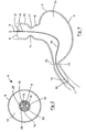
- FIG. 1 For determining the volume and the transverse cross-sectional area of a lumen or a vessel, such as a biological organ, for example, a stomach 3 of a subject, see Fig. 4 , although the apparatus 1 may be used for determining the volume and the transverse cross-sectional area of any lumen or vessel, be it a biological lumen or vessel or otherwise.
- the apparatus 1 comprises a balloon catheter also according to the invention and indicated generally by the reference numeral 4 which comprises an elongated catheter 5 extending between a proximal end 6 and a distal end 7 and having an inflatable element, namely, a balloon 8 located adjacent the distal end 7.
- the catheter 5 extends through the balloon 8 adjacent the distal end 7 of the catheter 5 and defines with the balloon 8 an annular hollow interior region 10 extending around the catheter 5.
- the balloon catheter 4 is adapted for inserting into the stomach 3 of the subject or a pouch formed in the stomach by bariatric surgery with the balloon 8 located in the stomach 3 or the pouch formed in the stomach.
- the balloon 8 is inflatable as will be described below by a liquid inflating medium, which in this case is an electrically conductive liquid medium, such as a saline solution, to define the interior volume of the stomach 3, so that the volume of the stomach 3 can be determined, as will also be described below.
- the balloon 8 is adapted so that in its unrestrained inflated state it is of circular transverse cross-section, and of substantially cylindrical configuration, defining a central longitudinally extending central axis, which coincides with the longitudinal central axis of the catheter 5.
- a pair of stimulating electrodes 12 for receiving an electric current stimulus signal of known constant value are located axially spaced apart on the catheter 5 within the hollow interior region 10 of the balloon 8.
- a plurality of axially spaced apart sensing electrodes 14 are located on the catheter 5 between and axially spaced apart from the stimulating electrodes 12 on which voltage signals are produced in response to the stimulus signal applied to the stimulating electrodes 12 when the balloon 8 is inflated with the electrically conductive liquid inflating medium.
- the voltage signals produced on the sensing electrodes 14 are indicative of the transverse cross-sectional area of the balloon 8 adjacent the respective sensing electrodes 14 when the balloon 8 is inflated with the electrically conductive liquid inflating medium.
- the stimulating electrodes 12 and the sensing electrodes 14 in this embodiment of the invention are band electrodes which extend completely around the catheter 5.
- a wire accommodating lumen 15 extending through the catheter 5 accommodates a communicating means, namely, a plurality of mutually insulated wires 16 from corresponding ones of the stimulating electrodes 12 and the sensing electrodes 14 to a multi-pin socket connector 17 at the proximal end 6 of the catheter 5.
- Wire accommodating bores 19 extending radially through the catheter 5 within the balloon 8 accommodate the wires 16 from the wire accommodating lumen 15 to the respective stimulating and sensing electrodes 12 and 14.
- a multi-pin plug connector 18 coupled to the socket connector 17 couples the wires 16 and in turn the stimulating electrodes 12 and the sensing electrodes 14 to a monitoring and control unit 22 for controlling the operation of the balloon catheter 4 for determining the volume and the transverse cross-sectional area of the balloon 8 as will be described below.
- a visual display means namely, a visual display screen 24 coupled to the monitoring and control unit 22 displays an approximate visual representation of a cross-section of the inflated balloon 8 as will also be described below.
- a keyboard 25 and a mouse 26 coupled to the monitoring and control unit 22 are provided for facilitating inputting of signals and commands to the monitoring and control unit 22 for controlling operation of the balloon catheter 4 for determining the volume and the transverse cross-sectional area of the balloon 8 and in turn the stomach 3.
- a flow lumen 28 extends through the catheter 5 from the proximal end 6 to the balloon 4 and communicates with the balloon 4 through radially extending flow bores 29 for accommodating the liquid inflating medium into the balloon 8 for inflating thereof.
- a return lumen 30 also extends through the catheter 5 from the proximal end 6 thereof to the balloon 8 and communicates with the balloon 8 through radially extending return bores 31 for accommodating the liquid inflating medium from the balloon 8 during deflating of the balloon 8 as will be described below.
- the flow lumen 28 and the return lumen 30 terminate in a coupler 33 adjacent the proximal end 6 of the catheter 5.
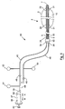
- a system also according to the invention and indicated generally by the reference numeral 35 for inflating the balloon 8 of the balloon catheter 4 with the liquid inflating medium comprises a pump means, which in this embodiment of the invention comprises a syringe 36.
- the syringe 36 comprises a syringe barrel 37 of circular transverse cross-section, which acts as a reservoir for the liquid inflating medium.
- the syringe barrel 37 terminates in a communicating port 38 through which the liquid inflating medium is accommodated during inflating and deflating of the balloon 8.
- a piston 39 carried on a distal end of a handle 40 is slideable within the syringe barrel 37 in a first direction in the direction of the arrow A into the syringe barrel 37 towards the communicating port 38 for discharging the liquid inflating medium from the syringe barrel 37 to the balloon 8 for inflating thereof, and in a second direction in the direction of the arrow B outwardly of the syringe barrel 37 for drawing the liquid inflating medium into the syringe barrel 37 from the balloon 8 for deflating the balloon 8.
- the syringe barrel 37 is configured with the syringe barrel 37 vertically orientated so that when the piston 39 is being urged in the first direction in the direction of the arrow A, the piston 39 is moved vertically downwardly within the syringe barrel 37, and when the piston 39 is being urged in the second direction in the direction of the arrow B, the piston 39 is moved vertically upwardly within the syringe barrel 37.
- the top surface of the liquid inflating medium in the syringe barrel 37 interfaces with the piston 39 so that any gaseous medium, typically, air in the liquid inflating medium rises through the liquid inflating medium in the syringe barrel 37 to the top surface thereof so that such gaseous medium is trapped between the top surface of the liquid inflating medium in the syringe barrel 37 and the piston 39.
- the syringe 36 as well as acting as a reservoir for the liquid inflating medium and a pump means for delivering and withdrawing the liquid inflating medium to and from the balloon 8, also acts as a separating means for separating the liquid inflating medium from gaseous medium in or entrained in the liquid inflating medium.
- a graduated scale 42 on the syringe barrel 37 is provided for indicating the volume of liquid inflating medium in the syringe barrel 37 or discharged therefrom.
- the main fluid line 44 is connected to the flow line 45 and the return line 46 by a valving means which comprises a first non-return valve 48 in the return line 46, and a second non-return valve 49 in the flow line 45.
- the first non-return valve 48 is configured to permit return flow of the liquid inflating medium from the balloon 8 to the syringe 36 through the return line 46 and the return lumen 30, and to prevent flow of the liquid inflating medium from the syringe 36 to the balloon 8 through the return lumen 30 and the return line 46.
- the second non-return valve 49 is configured to permit flow of the liquid inflating medium from the syringe 36 to the balloon 8 through the flow lumen 28 and the flow line 45, and to prevent flow of the liquid inflating medium from the balloon 8 to the syringe 36 through the flow line 45 and the flow lumen 28.
- a pressure sensing means for monitoring the pressure of the liquid inflating medium in the balloon 8 and in the flow and return lines 45 and 46 comprises a first pressure sensing means provided by a first main pressure sensor 50 and a first secondary pressure sensor 51, and a second pressure sensing means provided by a second main pressure sensor 52 and a second secondary pressure sensor 53.
- the first main pressure sensor 50 is a fine pressure sensor
- the first secondary pressure sensor 51 is a coarse pressure sensor.
- Both the first main pressure sensor 50 and the first secondary pressure sensor 51 are coupled to the return line 46 adjacent the first non-return valve 48 for monitoring the pressure of the liquid inflating medium in the return line 46.
- the second main pressure sensor 52 is a fine pressure sensor
- the second secondary pressure sensor 53 is a coarse pressure sensor. Both the second main pressure sensor 52 and the second secondary pressure sensor 53 are coupled to the flow line 45 adjacent the second non-return valve 49 for monitoring the pressure of the liquid inflating medium in the flow line 45.
- the monitoring and control unit 22 is coupled to the first main pressure sensor 50, the first secondary pressure sensor 51, the second main pressure sensor 52 and the second secondary pressure sensor 53 for reading signals from the respective first and second main and secondary pressure sensors 50, 51, 52 and 53 which are indicative of the pressure monitored by the respective pressure sensors 50 to 53.
- the monitoring and control unit 22 reads the signals from the first main pressure sensor 50 and the second secondary pressure sensor 53 during inflating of the balloon 8 by the syringe 36.
- the signals read from the first main pressure sensor 50 during inflating of the balloon 8 are indicative of the pressure of the liquid inflating medium in the balloon 8 during inflating thereof.
- the signals read from the second secondary pressure sensor 53 during inflating of the balloon 8 are indicative of the pressure at which the liquid inflating medium is being delivered by the syringe 36.
- the monitoring and control unit 22 determines the pressure of the liquid inflating medium in the balloon 8 during inflating thereof from the signals read from the first main pressure sensor 50, and also determines the pressure at which the liquid inflating medium is being delivered by the syringe 36 during inflating of the balloon 8 from the signals read from the second secondary pressure sensor 53.
- the monitoring and control circuit 22 reads signals from the first secondary pressure sensor 51 and the second main pressure sensor 52 during deflating of the balloon 8 by the syringe 36.
- the signals read from the second main pressure sensor 52 during deflating of the balloon 8 are indicative of the pressure of the liquid inflating medium in the balloon 8 during deflating thereof.
- the signals read from the first secondary pressure sensor 51 during deflating of the balloon 8 are indicative of the pressure at which the liquid inflating medium is being drawn into the syringe 36 during deflating of the balloon 8.
- the monitoring and control unit 22 determines the pressure of the liquid inflating medium in the balloon 8 during deflating thereof from the signals read from the second main pressure sensor 52, and also determines the pressure at which the liquid inflating medium is being drawn into the syringe 36 during deflating of the balloon 8 from the signals read from the first secondary pressure sensor 51.
- the monitoring and control circuit 22 can detect a blockage in any of the flow and return lines 45 and 46 and the flow and return lumens 28 and 30.
- a blockage in any of the flow and return lines 45 and 46 and the flow and return lumens 28 and 30 during inflating of the balloon 8 would be detected by an unusual rise in the pressure read from the second secondary pressure sensor 53.
- the monitoring and control circuit 22 can detect a blockage in any of the flow and return lines 45 and 46 and the flow and return lumens 28 and 30. A blockage in any of the flow and return lines 45 and 46 and the flow and return lumens 28 and 30 would be detected by an unusual fall in the pressure read from the first secondary pressure sensor 51.
- the pressure at which the balloon 8 is inflated during a procedure for determining the volume and/or transverse cross-sectional area of a vessel or lumen is relatively low. This is because the balloon 8 during such a procedure only has to be inflated to a state where it fills the vessel or lumen, the volume and/or transverse cross-sectional area of which is to be determined. Accordingly, the balloon catheter 4 in this embodiment of the invention is a relatively low pressure balloon catheter.
- the first main pressure sensor 50 has a workable pressure range of -50 millibars to +200 millibars.
- the first secondary pressure sensor 51 has a workable pressure range from -1,000 millibars to +1,000 millibars.
- the second main pressure sensor 52 has a workable range of -50 millibars to 200 millibars, while the second secondary pressure sensor 53 has a workable pressure range from 0 millibars to +1,000 millibars.
- the apparatus 1 according to the invention and the balloon catheter 4 also according to the invention may be provided for dilating an occlusion in a vessel or a lumen, or for ablating an occlusion in a vessel or lumen.
- one or more ablating electrodes would be provided on the outer circumferential surface of the balloon 8 of the balloon catheter 4 for carrying out the ablating procedure.
- the balloon catheter would have to operate at a relatively high pressure, and accordingly, the first main and secondary pressure sensors 50 and 51, and the second main and secondary pressure sensors 52 and 53 would be provided to operate at appropriate workable pressure ranges.
- the apparatus 1 according to the invention and the balloon catheter 4 according to the invention are provided for other high pressure operations, the first main and secondary pressure sensors 50 and 51 and the second main and secondary pressure sensors 52 and 53 would also be provided to have an appropriate workable pressure range.
- the pressure monitored by the first main pressure sensor 50 produces a true reading of the pressure of the liquid inflating medium in the balloon 8 during inflating of the balloon 8
- the second main pressure sensor 52 produce a relatively true pressure of the liquid inflating medium in the balloon 8 during deflating of the balloon 8.
- the syringe barrel 37 is fully charged with the liquid inflating medium by drawing liquid inflating medium from a suitable source (not shown) into the syringe barrel 37 through the communicating port 38 by the piston 39 while the syringe 36 is disconnected from the main fluid line 44 and is connected to the suitable source.
- the syringe 36 is disconnected from the suitable source, and is connected to the main fluid line 44.
- the piston 39 is moved in the first direction, namely, in the direction of the arrow A for discharging the liquid inflating medium from the syringe barrel 37 through the main line 44 and in turn through the flow line 45 and the flow lumen 28 to the balloon 8 for inflating thereof.
- the piston 39 is again urged in the first direction, namely, in the direction of the arrow A to deliver the liquid inflating medium in the syringe barrel 37 through the flow line 45 and the flow lumen 28 to re-inflate the balloon 8. Any residual air in the flow line 45, the flow lumen 28 and the balloon 8 during re-inflating of the balloon 8 is discharged into the return lumen 30 and the return line 46.
- the piston 39 is urged in the first direction in the direction of the arrow A until only a small amount of liquid inflating medium remains in the lower end of the syringe barrel 37 adjacent the communicating port 38.
- stage operation of the piston 39 ceases in order to avoid any danger of the air entrapped between the piston 39 and the top surface of the liquid inflating medium in the syringe barrel 37 being discharged into the main fluid line 44.
- the balloon 8 is deflated by operating the piston 39 in the second direction, namely, in the direction of the arrow B to draw the liquid inflating medium from the balloon 8 through the return lumen 30 and the return line 46 to the syringe 36.
- any residual air in the balloon 8 and the return lumen 30 and the return line 46 after the previous inflating the balloon 8 is drawn along with the liquid inflating medium into the syringe barrel 37.
- the residual air rises through the liquid inflating medium in the syringe barrel 37 to the top thereof and is entrapped with the air already entrapped between the piston 39 and the top surface of the liquid inflating medium in the syringe barrel 37.
- the balloon 8 is re-inflated with the liquid inflating medium by urging the piston 39 in the first direction, namely, in the direction of the arrow A for discharging the liquid inflating medium in the syringe barrel 37 into the balloon 8 through the flow line 45 and the flow lumen 28.
- the piston 39 is operated in the direction of the arrow A until only a small amount of the liquid inflating medium remains in the lower end of the syringe barrel 37 adjacent the communicating port 38, and further operation of the piston 39 ceases in order to avoid any danger of the air entrapped between the piston 39 and the top surface of the liquid inflating medium in the syringe barrel 37 entering the main fluid line 44.
- the balloon 8 should be inflated with the liquid inflating medium, and all the air should have been extracted from the balloon 8, the flow and return lumens 28 and 30 and the flow and return lines 45 and 46 as well as the main fluid line 44. However, if it is felt that residual air still remains in the balloon 8, the flow and return lumens 28 and 30 or the flow and return lines 45 and 46 or the main fluid line 44, the balloon 8 can be again deflated and re-inflated with the liquid inflating medium as just described.
- This sequence of deflating and re-inflating cycles of the balloon 8 with the liquid inflating medium may continue until all residual air has been removed from the balloon 8, the flow and return lumens 28 and 30, the flow and return lines 45 and 46 and the main fluid line 48, or until the level of residual air remaining in the balloon 8, the flow and return lumens 28 and 30, the flow and return lines 45 and 46 and the main fluid line 44 is sufficiently low that the pressure values read from the first and second main pressure sensors 50 and 52 as described above are true values of the pressure of the liquid inflating medium in the balloon 8 during inflating and deflating thereof, as the case may be.
- the pressure read from the first main pressure sensor 50 should be a true reading of the pressure of the liquid inflating medium in the balloon 8 during inflating thereof
- the pressure read from the second main pressure sensor 52 should be a true reading of the pressure of the liquid inflating medium in the balloon 8 during deflating of the balloon 8.
- a relatively accurate determination can be made as to when the balloon 8 has been inflated to a state where it fills the lumen or vessel, or in other words, defines the interior of the lumen or vessel within which the balloon 8 is located. It has been found that during inflating of the balloon 8 with the liquid inflating medium, the pressure of the liquid inflating medium in the balloon 8 remains substantially constant, or the rate of change of pressure of the liquid inflating medium in the balloon 8 per unit volume of liquid inflating medium delivered into the balloon 8 remains substantially constant, until the balloon 8 has been inflated to the state where it fills the lumen or vessel within which it is located.
- the pressure of the balloon 8 on the inner wall of the lumen or vessel resulting from further inflating of the balloon causes the pressure of the liquid inflating medium in the balloon 8 to increase, or alternatively, causes the rate of change of the pressure in the liquid inflating medium per unit volume of the liquid inflating medium delivered into the balloon 8 to increase.
- a determination can be made as to when the balloon 8 has been inflated to a state where it fills the lumen or vessel, in other words, defines the interior of the lumen or vessel within which it is located.
- the volume of the syringe barrel 37 is such as to contain sufficient liquid inflating medium, so that when the balloon 8 has been inflated to its maximum volume with the flow and return lumens 28 and 30 and the flow and return lines 45 and 46 as well as the main fluid line 44 filled with the liquid inflating medium, there is still liquid inflating medium remaining in the barrel 37 of the syringe 36.
- the monitoring and control unit 22 comprises a signal generator 58 for generating the constant current signal of known current for applying to the stimulating electrodes 12.
- a signal processing means namely, a microprocessor 59 is programmed for operating the signal generator 58 to generate the constant current signal, and to simultaneously read voltage signals produced on the sensing electrodes 14 in response to the constant current signal on the stimulating electrodes 12 when the balloon 8 is inflated with the liquid inflating medium, which as discussed above, is an electrically conductive medium.
- the microprocessor 59 is also programmed for determining the transverse cross-sectional area of the inflated balloon 8 adjacent the respective sensing electrodes 14 from the voltages read from the sensing electrodes 14, and to determine the volume of the inflated balloon 8.
- the volume is determined by computing the volumes of the inflated balloon 8 between adjacent sensing electrodes 14 by multiplying the computed transverse cross-sectional area adjacent each sensing electrode 14 by the spacing between that sensing electrode 14 and the next adjacent sensing electrodes 14.
- the total volume of the inflated balloon 8 between the extreme-most sensing electrodes 14 is determined by summing the computed volumes of the balloon 8 between the respective adjacent sensing electrodes 14.
- the volume of the inflated balloon 8 between any pair of sensing electrodes 14 may be computed by summing the volumes computed between the adjacent sensing electrodes 14 which are located between the two sensing electrodes 14 between which the volume of the inflated balloon 8 is to be determined.
- the microprocessor 59 is programmed to compute the volume of the inflated balloon 8 between any pair of selected sensing electrodes 14.
- the microprocessor 59 is appropriately programmed to operate the visual display screen 24 to display the value of the volume of the inflated balloon 8 between any selected pair of sensing electrodes 14.
- the microprocessor 59 is also programmed to operate the visual display screen 24 to graphically display a graphical representation of an approximate longitudinal cross-section of the inflated balloon 8 between the extreme-most sensing electrodes 14, with a representation of the locations of the sensing electrodes 14 superimposed thereon for facilitating selection of any pair of the sensing electrodes between which the volume of the balloon is to be computed.
- the microprocessor 59 also is programmed to operate the visual display screen 24 to display the transverse cross-sectional area of the inflated balloon 8 adjacent the respective sensing electrodes 14.
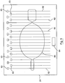
- FIG. 5 A typical display of a graphical representation 60 of an approximate longitudinal cross-section of the inflated balloon 8 when inflated which is displayed on the visual display screen 24 is illustrated in Fig. 5 .
- the locations of the sensing electrodes 14 are represented by lines 62 superimposed on the graphical representation 60 of the inflated balloon 8.
- the transverse cross-sectional area of the inflated balloon 8 at the respective sensing electrodes 14 is displayed in the windows 63 corresponding to the lines 62.
- the volume of the inflated balloon 8 between any selected pair of the sensing electrodes 14 is displayed in a window 63.
- the visual display screen 24 may be a touch screen, and in which case, the pair of sensing electrodes 14 between which the volume of the balloon 8 is to be determined would be selected by touching the relevant pair of lines 62 representative of the two sensing electrodes 14 between which the volume of the inflated balloon 8 is to be determined.
- the lines 62 representative of the pair of sensing electrodes 14 between which the volume of the inflated balloon 8 is to be determined may be selected by moving a cursor on the visual display screen 24 to the relevant lines 62 and selecting the lines 62 by the mouse 26.
- the lines 62 representative of the sensing electrodes 14 may be numbered, and the identifying numbers of the lines 62 representative of the pair of sensing electrodes 14 between which the volume of the inflated balloon 8 is to be determined would be inputted by keying in the identification numbers of the respective lines 62 via the keyboard 25.
- the microprocessor 59 is programmed to read signals from the first and second main and secondary pressure sensors 50, 51, 52 and 53 during inflating and deflating of the balloon 8 by the syringe 36, and to control the operation of the syringe 36 in response to pressure values read from the pressure sensors 50, 51, 52 and 53.
- a linear motor (not shown) operates the handle 40 and the piston 39 of the syringe 36 for inflating and deflating the balloon 8 under the control of the microprocessor 59.
- the microprocessor 59 also operates the visual display screen 24 to display the pressure values read from the first and second main and secondary pressure sensors 50, 51, 52 and 53, which are continuously updated during inflating and deflating of the balloon 8.
- the microprocessor 59 is programmed to sound an alarm in the event of a blockage being detected in any of the flow and return lines and lumens 45, 46 and 28 and 30, and to deactivate the linear motor (not shown) which operates the syringe 36.
- the microprocessor 59 is also programmed to display a message indicating the detection of the blockage on the visual display screen 24.
- the distal end 7 of the balloon catheter 4 with the balloon 8 deflated is entered nasally or orally into the oesophagus 70 of the subject and is urged downwardly through the oesophagus 70 and through the lower oesophageal sphincter 71 into the stomach 3 until the distal end of the balloon 8 passes through the lower sphincter 72 of the stomach 3.
- the balloon 8 should be located within the stomach 3 of the subject with the distal end thereof projecting through the lower sphincter 72 and the proximal end thereof projecting through the lower oesophageal sphincter 71.
- the balloon 8 is then inflated with the liquid inflating medium as already described under the control of the microprocessor 59. Initially the syringe 36 is charged with the liquid inflating medium while the communicating port 38 of the syringe barrel 37 is disconnected from the main fluid line 44 and connected to the suitable source of the liquid inflating medium.
- the piston 39 is operated under the control of the microprocessor 59 for delivering the liquid inflating medium from the syringe 36 to the balloon 8 for inflating thereof.
- the liquid inflating medium passes through the flow line 45 and the flow lumen 28 into the balloon 8, air located therein is displaced into the return lumen 30 and the return line 46.
- the piston 39 of the syringe 36 is then operated under the control of the microprocessor 59 to deflate the balloon 8 by drawing the liquid inflating medium and the air from the balloon 8 through the return lumen 30 and the return line 46. Air drawn into the syringe 36 is separated therein with the air being entrapped between the piston 39 and the top surface of the liquid inflating medium.
- the balloon 8 is then re-inflated by operating the piston 39 of the syringe 36 under the control of the microprocessor 59 to urge the liquid inflating medium from the syringe 36 to the balloon 8 through the flow line 45 and the flow lumen 28, thereby further displacing any residual air in the flow lumen 28, the flow line 45 and the balloon 8 into the return lumen 30 and the return line 46.
- the balloon is deflated by operating the piston 39 under the control of the microprocessor 59 to draw the liquid inflating medium together with any residual air remaining in the balloon 8, the return lumen 30 and the return line 46 into the syringe 36, where the residual air is again separated from the liquid inflating medium.
- the piston 39 is again operated under the control of the microprocessor 59 for delivering the liquid inflating medium from the syringe 36 to the balloon 8 for inflating thereof through the flow line 45 and the flow lumen 28.
- the flow and return lumens 28 and 30 and the flow and return lines 45 and 46 is such as to prevent a true reading of the pressure of the liquid inflating medium in the balloon 8 being obtained from the appropriate one of the first and second main pressure sensors 50 and 52, depending on whether the balloon 8 is being inflated or deflated, a further cycle of deflating the balloon 8 and re-inflating the balloon 8 is carried out as already described under the control of the microprocessor 59.
- Further cycles of deflating and re-inflating the balloon 8 may be carried out until substantially all of the residual air in the liquid inflating medium has been separated and displaced from the liquid inflating medium, or at least until the level of any residual air in the liquid inflating medium in the balloon 8, the flow and return lumens 28 and 30 and the flow and return lines 45 and 46 is at a level which permits a true reading of the pressure of the liquid inflating medium in the balloon 8 to be obtained from the appropriate one of the first and second main pressure sensors 50 and 52.
- the flow and return lumens 28 and 30 and the flow and return lines 45 and 46 are at a level which permits a true reading of the pressure of the liquid inflating medium in the balloon 8 to be read from the appropriate one of the first and second main pressure sensors 50 and 52, operation of the balloon catheter 4 under the control of the microprocessor 59 continues as follows.
- the microprocessor 59 operates the signal generator 58 to apply the constant current signal to the stimulating electrodes 12, and the voltage signals produced on the sensing electrodes 14 in response to the constant current signal are read by the microprocessor 59, which then in turn computes the transverse cross-sectional area values of the balloon 8 adjacent the respective sensing electrodes 14, and produces the graphical representation 60 of the approximate longitudinal cross-section of the balloon 8 which is displayed on the visual display screen 24 with the lines 62 representative of the,sensing electrodes 14 superimposed thereon.
- the microprocessor 59 also operates the visual display screen 24 for displaying the values of the transverse cross-sectional area of the balloon 8 in the window 63 adjacent the respective sensing electrodes 14.
- the lines 62 representative of the sensing electrodes 68 between which the volume of the balloon is to be computed corresponding to the stomach 3 are selected as already described and the microprocessor 59 computes the volume which is displayed in the window 64.
- the balloon 8 is deflated by operating the syringe 36 under the control of the microprocessor 59 to draw the liquid inflating medium from the balloon 8 through the return lumen 30 and the return line 46.
- the balloon catheter 4 is then withdrawn through the oesophagus 70 and removed from the subject.
- the microprocessor 59 determines from the signals read from the second and first secondary pressure sensors 53 and 51, respectively, that any one of the flow and return lines 45 and 46 and the flow and return lumens 28 and 30 are blocked, the microprocessor 59 deactivates the linear motor which operates the syringe 36, thereby terminating inflating or deflating of the balloon 8, sounds an alarm and operates the visual display screen 24 to display a message indicating the detection of the blockage.
- the microprocessor 59 may be programmed to apply the constant current signal to the stimulating electrodes 12, and to read the voltage signals produced on the sensing electrodes 14 simultaneously while inflating and deflating the balloon 8, in order that the transverse cross-sectional area of the balloon 8 adjacent the respective sensing electrodes 14 may be monitored during inflating and/or deflating of the balloon 8.
- the computed and monitored values of the transverse cross-sectional area of the balloon 8 adjacent the respective sensing electrodes 14 would then be displayed and continuously updated in the windows 63 on the display screen 24.
- the volume of the balloon between the extreme-most or selected ones of the sensing electrodes could also be displayed and continuously updated in the window 24 of the display screen 24 during inflating and/or deflating of the balloon 8.
- a system according to another embodiment of the invention also for inflating a balloon 8 of a balloon catheter 4 for in turn determining the volume and the transverse cross-sectional area of a vessel or lumen.
- the system 80 is substantially similar to the system 35 and similar components are identified by the same reference numerals.
- the first and second secondary pressure sensors 51 and 53 have been omitted, and a third pressure sensor 81, which in this embodiment of the invention is a coarse pressure sensor is coupled to the main fluid line 44 for monitoring the pressure of the liquid inflating medium in the main fluid line 44.
- the third pressure sensor 81 replaces the first and second secondary pressure sensors 51 and 53.
- the syringe 36 is horizontally orientated, instead of being vertically orientated.
- the communicating port 38 is offset from the central axis of the syringe barrel 37 towards a sidewall thereof, and the syringe 36 is oriented with the communicating port 38 located at a lower portion of the syringe, so that the top surface of the liquid inflating medium in the syringe barrel 37 is always above the level of the communicating port 38.
- system 80 is similar to the system 35, as is its use.
- the apparatus and the system for inflating the balloon of the balloon catheter have been described for use in determining the volume and the transverse cross-sectional area of the stomach of a subject, the apparatus and the system may be used for determining the volume and/or the transverse cross-sectional area of a pouch formed in a stomach by bariatric surgery. Indeed, it will be readily apparent to those skilled in the art that the apparatus and the system may be used for determining the volume of any lumen, vessel or organ biological or otherwise, and indeed, the apparatus may be used for determining the volume and/or transverse cross-sectional area of any other vessel be it biological or otherwise.
- an inflatable element may be used for inflating any type of inflatable element be it a balloon of a balloon catheter, or an inflatable element of any other type.
- the balloon catheter may be used for determining the transverse cross-sectional area of a sphincter, a lumen or any other such lumen or vessel. It is also envisaged that the balloon catheter may be used for determining the transverse cross-sectional area of an occlusion in a lumen or vessel, for example, an occlusion in the oesophagus, caused by a diseased part of the oesophagus.
- the balloon catheter may be used for determining the transverse cross-sectional area of the colon, the intestine, or an occlusion in the colon or intestine resulting from a diseased portion of the colon or intestine.
- the balloon catheter may also be used for determining the volume and transverse cross-sectional area of a lumen or vessel in the cardiovascular system, and for determining the transverse cross-sectional area of an occlusion in a vessel of the cardiovascular system, resulting, for example, of a build-up of plaque in the vessel.
- the balloon catheter according to the invention may be used for dilating an occlusion in a vessel or lumen, for example, for dilating an occlusion in the oesophagus, intestine or colon resulting from a diseased portion of the oesophagus, intestine or colon, and in which case, the transverse cross-sectional area of the balloon of the balloon catheter adjacent the respective sensing electrodes would be continuously monitored during inflating of the balloon, and the computed values of the transverse cross-sectional area would be displayed on the visual display screen.
- the pressure of the liquid inflating medium in the balloon would also be monitored, in order to avoid any danger of rupturing the oesophagus, intestine or colon, as the case may be.
- the balloon catheter according to the invention may be used for ablating tissue in a vessel or lumen, for example, in the oesophagus, an intestine, colon, and indeed, in the stomach or a pouch of the stomach of a subject, or in a blood vessel, or in any other vessel or lumen.
- a vessel or lumen for example, in the oesophagus, an intestine, colon, and indeed, in the stomach or a pouch of the stomach of a subject, or in a blood vessel, or in any other vessel or lumen.
- first main and secondary pressure sensors and second main and secondary pressure sensors
- first and second main pressure sensors may be provided, or alternatively, only the first and second secondary pressure sensors may be provided.
- a single pressure sensor only may be provided in the return line or lumen.
- first main pressure sensor and a second secondary pressure sensor could be provided only. Needless to say, other appropriate combinations of first and second main and secondary pressure sensors may be provided.
- any other suitable pump means for delivering and withdrawing liquid inflating medium to the inflatable element may be provided. Indeed, in certain cases, it is envisaged that separate pump means may be provided for inflating and deflating the inflatable element.
Landscapes
- Health & Medical Sciences (AREA)
- Life Sciences & Earth Sciences (AREA)
- Heart & Thoracic Surgery (AREA)
- Animal Behavior & Ethology (AREA)
- Veterinary Medicine (AREA)
- Biophysics (AREA)
- Engineering & Computer Science (AREA)
- Public Health (AREA)
- Biomedical Technology (AREA)
- General Health & Medical Sciences (AREA)
- Pulmonology (AREA)
- Hematology (AREA)
- Anesthesiology (AREA)
- Child & Adolescent Psychology (AREA)
- Dentistry (AREA)
- Oral & Maxillofacial Surgery (AREA)
- Physics & Mathematics (AREA)
- Pathology (AREA)
- Medical Informatics (AREA)
- Molecular Biology (AREA)
- Surgery (AREA)
- Media Introduction/Drainage Providing Device (AREA)
Claims (15)
- Système pour gonfler un élément gonflable (8) avec un milieu gonflable liquide, le système comprenant une conduite d'écoulement (28, 45) communiquant avec l'élément gonflable (8), une conduite de retour (30, 46) communiquant avec l'élément gonflable (8) et un moyen de pompe (39) étant fonctionnel pour délivrer le milieu gonflable liquide à l'élément gonflable (8) pour un gonflage de celui-ci, caractérisé en ce qu'un moyen de séparation (36) est prévu pour séparer le milieu gonflable liquide d'un milieu gazeux à l'intérieur de celui-ci, et les conduites d'écoulement et de retour (28, 45, 30, 46) font communiquer l'élément gonflable (8) avec le moyen de séparation (36) via un moyen de vanne (48, 49) configuré pour coupler sélectivement et alternativement le moyen de séparation (36) à la conduite d'écoulement (28, 45) et à la conduite de retour (30, 46), et le moyen de pompe (39) est sélectivement et alternativement fonctionnel pour délivrer le milieu gonflable liquide depuis le moyen de séparation (36) via la conduite d'écoulement (28, 45) jusqu'à l'élément gonflable (8) pour le gonflage de celui-ci, et pour délivrer le milieu gonflable liquide depuis l'élément gonflable (8) via la conduite de retour (30, 46) jusqu'au moyen de séparation (36) pour séparer le milieu gonflable liquide du milieu gazeux à l'intérieur de celui-ci, de sorte qu'après un gonflage initial de l'élément gonflable (8) avec le milieu gonflable liquide via la conduite d'écoulement (28, 45), l'élément gonflable (8) est dégonflé en délivrant le milieu gonflable liquide depuis l'élément gonflable (8) via la conduite de retour (30, 46) jusqu'au moyen de séparation (36) et l'élément gonflable (8) est regonflé avec le milieu gonflable liquide via la conduite d'écoulement (28, 45) depuis le moyen de séparation (36) avec le milieu gazeux séparé de celui-ci.
- Système selon la revendication 1 caractérisé en ce que le moyen de pompe (39) est fonctionnel pour délivrer séquentiellement le milieu gonflable liquide depuis l'élément gonflable (8) jusqu'au moyen de séparation (36) via la conduite de retour (30, 46), et depuis le moyen de séparation (36) jusqu'à l'élément gonflable (8) via la conduite d'écoulement (28, 45) jusqu'à ce que le niveau de milieu gazeux dans le milieu gonflable liquide eut été réduit à un niveau souhaité.
- Système selon la revendication 1 ou 2 caractérisé en ce que le moyen de vanne (48, 49) comprend un premier clapet anti-retour (40) situé dans la conduite de retour (30, 46) faisant communiquer la conduite de retour (30, 46) avec le moyen de séparation (36), un second clapet anti-retour (49) est situé dans la conduite d'écoulement (28, 45) faisant communiquer la conduite d'écoulement (28, 45) avec le moyen de séparation (36), le premier clapet anti-retour (48) étant configuré pour permettre un écoulement du milieu gonflable liquide via la conduite de retour (30, 46) depuis l'élément gonflable (8) jusqu'au moyen de séparation (36), et le second clapet anti-retour (49) étant configuré pour permettre un écoulement du milieu gonflable liquide via la conduite d'écoulement (28, 45) depuis le moyen de séparation (36) jusqu'à l'élément gonflable (8).
- Système selon l'une quelconque des revendications précédentes caractérisé en ce qu'un moyen de détection de pression (50, 51, 52, 53) est prévu pour surveiller à distance la pression du milieu gonflable liquide dans l'élément gonflable (8).
- Système selon la revendication 4 caractérisé en ce que le moyen de détection de pression (50, 51, 52, 53) comprend un premier moyen de détection de pression (50, 51) situé dans la conduite de retour (30, 46) intermédiaire du moyen de séparation (36) et de l'élément gonflable (8) adjacent au moyen de vanne (48, 49).
- Système selon la revendication 4 ou 5 caractérisé en ce que le moyen de détection de pression (50, 51, 52, 53) comprend un second moyen de détection de pression (52, 53) situé dans la conduite d'écoulement (28, 45) intermédiaire du moyen de séparation (36) et de l'élément gonflable (8) adjacent au moyen de vanne (48, 49).
- Système selon l'une quelconque des revendications précédentes caractérisé en ce que le moyen de séparation (36) comprend un réservoir (37) pour le milieu gonflable liquide, le réservoir (37) étant configuré de telle sorte que le milieu gazeux dans le milieu gonflable liquide monte jusqu'à une surface supérieure du milieu gonflable liquide dans le réservoir (37) pour séparer le milieu gonflable liquide du milieu gazeux.
- Système selon la revendication 7 caractérisé en ce que le réservoir (37) comprend un cylindre (37) allongé d'une seringue (36), le cylindre (37) présentant un orifice de communication (38) pour faire communiquer le cylindre (37) avec les conduites d'écoulement et de retour (28, 45, 30, 46), et le moyen de pompe (39) comprend un piston (39) pouvant coulisser axialement à l'intérieur du cylindre (37) de la seringue (36) dans un premier sens pour faire couler le milieu gonflable liquide jusque dans le cylindre (37), et dans un second sens opposé pour évacuer le milieu gonflable liquide depuis le cylindre (37).
- Système selon la revendication 7 caractérisé en ce que la seringue (36) est configurée de telle sorte que la surface supérieure du milieu gonflable liquide dans le cylindre (37) de seringue se situe au-dessus du niveau de l'orifice de communication (38) afin que le milieu gonflable liquide séparé du milieu gazeux puisse être évacué depuis le cylindre (37) de seringue via l'orifice de communication (38) sans le milieu gazeux.
- Système selon la revendication 8 ou 9 caractérisé en ce que la seringue (36) est configurée de telle sorte que le milieu gazeux dans le milieu gonflable liquide monte via le milieu gonflable liquide dans le cylindre (37) jusqu'à une interface milieu gonflable liquide / piston de telle sorte que le milieu gazeux soit piégé entre le piston (39) et le milieu gonflable liquide, et la seringue (36) est configurée de telle sorte que le piston (39) soit fonctionnel dans le premier sens dans un sens globalement ascendant, et dans le second sens dans un sens globalement descendant.
- Système selon la revendication 8 ou 9 caractérisé en ce que la seringue (36) est configurée de telle sorte que le piston (39) soit fonctionnel dans le premier sens et le second sens le long d'un axe essentiellement horizontal.
- Cathéter à ballonnet comprenant un cathéter (5) allongé s'étendant entre une extrémité proximale (6) et une extrémité distale (7), et un élément gonflable (8) situé sur le cathéter (5) avec le cathéter (5) s'étendant via l'élément gonflable (8), et l'élément gonflable (8) définissant avec le cathéter (5) une région intérieure creuse (10) annulaire s'étendant autour du cathéter (5), une lumière d'écoulement (28) s'étendant depuis l'extrémité proximale (6) du cathéter (5) jusqu'à l'élément gonflable (8) et communiquant avec l'élément gonflable (8), une lumière de retour (30) s'étendant depuis l'extrémité proximale (6) du cathéter (5) jusqu'à l'élément gonflable (8) et communiquant avec l'élément gonflable (8), et un système (35) selon l'une quelconque des revendications 1 à 11 avec la conduite d'écoulement (45) du système (35) couplée à la lumière d'écoulement (28) du cathéter (5) adjacente à l'extrémité proximale (6) de celui-ci, et la conduite de retour (46) du système (35) couplée à la lumière de retour (30) du cathéter (5) adjacente à l'extrémité proximale (6) de celui.
- Cathéter à ballonnet selon la revendication 12 caractérisé en ce qu'au moins une électrode de stimulation (12) est située à l'intérieur de l'élément gonflable (8) sur l'un des cathéters (5) et une surface intérieure de l'élément gonflable (8), et au moins une électrode de détection (14) est située à l'intérieur de l'élément gonflable (8) sur l'un des cathéters (5) et la surface intérieure de l'élément gonflable (8) axialement espacée de la au moins une électrode de stimulation (12), et un moyen de communication (16) est prévu pour faciliter l'application d'un signal de stimulation à la au moins une électrode de stimulation (12) et la lecture d'un signal produit sur la au moins une électrode de détection (14) en réponse au signal de stimulation appliqué à la au moins une électrode de stimulation (12) lorsque l'élément gonflable (18) est gonflé avec un milieu gonflable liquide électriquement conducteur.
- Appareil pour déterminer l'un parmi un volume et une zone à section transversale de l'un parmi une lumière et un vaisseau, l'appareil comprenant un cathéter à ballonnet (4) comprenant un cathéter (5) allongé s'étendant entre une extrémité proximale (6) et une extrémité distale (7), un élément gonflable (8) situé sur le cathéter (5) avec le cathéter (5) s'étendant via l'élément gonflable (8), et l'élément gonflable (8) définissant avec le cathéter (5) une région intérieure creuse (10) annulaire s'étendant autour du cathéter (5), une lumière d'écoulement (28) s'étendant via le cathéter (5) depuis l'extrémité proximale (6) de celui-ci jusqu'à l'élément gonflable (8) communiquant avec l'élément gonflable (8), une lumière de retour (30) s'étendant via le cathéter (5) depuis l'extrémité proximale (6) de celui-ci jusqu'à l'élément gonflable (8) communiquant avec l'élément gonflable (8), au moins une électrode de stimulation (12) située à l'intérieur de la région intérieure creuse (10) de l'élément gonflable (8) sur l'un parmi le cathéter (5) et une surface intérieure de l'élément gonflable (8), au moins une électrode de détection (14) située à l'intérieur de la région intérieure creuse (10) de l'élément gonflable (8) sur l'un parmi le cathéter (5) et la surface intérieure de l'élément gonflable (8) axialement espacée de la au moins une électrode de stimulation (12), un moyen de communication (16) pour faciliter l'application d'un signal de stimulation à la au moins une électrode de stimulation (12) et la lecture d'un signal produit sur la au moins une électrode de détection (14) en réponse au signal de stimulation appliqué à la au moins une électrode de stimulation (12) lorsque l'élément gonflable (8) est gonflé avec un milieu gonflable liquide électriquement conducteur, un système (35) selon l'une quelconque des revendications 1 à 11 pour gonfler l'élément gonflable (8) avec un milieu gonflable liquide électriquement conducteur, la conduite d'écoulement (45) du système (35) étant couplée à la lumière d'écoulement (28) du cathéter à ballonnet (4) adjacente à l'extrémité proximale (6) du cathéter (5), et la conduite de retour (46) du système (35) étant couplée à la lumière de retour (30) du cathéter à ballonnet (4) adjacente à l'extrémité proximale (6) du cathéter (5), un générateur de signal (58) en communication avec la au moins une électrode de stimulation (12) via le moyen de communication (16) pour appliquer un signal de stimulation à la au moins une électrode de stimulation (12), et un moyen de traitement de signal (59) en communication avec la au moins une électrode de détection (14) via le moyen de communication (16) pour lire un signal produit sur la au moins une électrode de détection (14) en réponse au signal de stimulation appliqué à la au moins une électrode de stimulation (12) lorsque l'élément gonflable (8) est gonflé avec le milieu gonflable liquide électriquement conducteur, le moyen de traitement de signal (59) étant conçu pour déterminer l'un parmi le volume et la zone à section transversale de l'élément gonflable (8) gonflé.
- Appareil selon la revendication 14 caractérisé en ce qu'au moins deux électrodes de stimulation (12) axialement espacées sont prévues à l'intérieur de l'élément gonflable (8), et une pluralité d'électrodes de détection (14) axialement espacées sont situées entre et espacées des électrodes de stimulation (12).
Applications Claiming Priority (2)
| Application Number | Priority Date | Filing Date | Title |
|---|---|---|---|
| IE20080265 | 2008-04-09 | ||
| PCT/IE2009/000014 WO2009125380A1 (fr) | 2008-04-09 | 2009-04-09 | Système et procédé pour gonfler un élément gonflable avec un milieu de gonflage liquide et cathéter à ballonnet gonflé par le système et le procédé |
Publications (2)
| Publication Number | Publication Date |
|---|---|
| EP2273921A1 EP2273921A1 (fr) | 2011-01-19 |
| EP2273921B1 true EP2273921B1 (fr) | 2018-10-03 |
Family
ID=40688478
Family Applications (1)
| Application Number | Title | Priority Date | Filing Date |
|---|---|---|---|
| EP09729426.8A Not-in-force EP2273921B1 (fr) | 2008-04-09 | 2009-04-09 | Système pour gonfler un élément gonflable avec un milieu de gonflage liquide et cathéter à ballonnet gonflé par le système |
Country Status (3)
| Country | Link |
|---|---|
| US (1) | US8486011B2 (fr) |
| EP (1) | EP2273921B1 (fr) |
| WO (1) | WO2009125380A1 (fr) |
Families Citing this family (35)
| Publication number | Priority date | Publication date | Assignee | Title |
|---|---|---|---|---|
| EP2405965B1 (fr) * | 2009-03-09 | 2014-02-26 | Flip Technologies Limited | Catheter a ballonnet et appareil de surveillance de la coupe transversale d'une stomie |
| EP2962770B1 (fr) * | 2009-07-24 | 2017-03-22 | Bayer Healthcare LLC | Système médical d'injection multifluide |
| US9439633B2 (en) * | 2009-10-09 | 2016-09-13 | Flip Technologies Limited | Device and a method for facilitating monitoring the cross-section of a gastric sleeve during formation thereof |
| EP2353501A1 (fr) * | 2010-02-09 | 2011-08-10 | Sanofi-Aventis Deutschland GmbH | Dispositif de post-conditionnement contrôlé d'informatique |
| US20140155684A1 (en) * | 2010-04-30 | 2014-06-05 | Abbott Cardiovascular Systems Inc. | Method for increased uptake of beneficial agent and ejection fraction by postconditioning procedures |
| US8540669B2 (en) | 2010-04-30 | 2013-09-24 | Abbott Cardiovascular Systems Inc. | Catheter system providing step reduction for postconditioning |
| US8783001B2 (en) * | 2010-12-10 | 2014-07-22 | Tie Not Incorporated | Balloon filling device |
| US9180281B2 (en) | 2011-04-08 | 2015-11-10 | Sanovas, Inc. | Adjustable balloon catheter for extravasated drug delivery |
| CN103118595B (zh) * | 2011-07-06 | 2015-09-16 | 株式会社东芝 | 医用图像诊断装置 |
| US9238125B2 (en) | 2013-01-31 | 2016-01-19 | Medtronic Xomed, Inc. | Inflation device for balloon sinus dilation |
| US9694163B2 (en) | 2013-12-17 | 2017-07-04 | Biovision Technologies, Llc | Surgical device for performing a sphenopalatine ganglion block procedure |
| US9516995B2 (en) * | 2013-12-17 | 2016-12-13 | Biovision Technologies, Llc | Surgical device for performing a sphenopalatine ganglion block procedure |
| US9510743B2 (en) | 2013-12-17 | 2016-12-06 | Biovision Technologies, Llc | Stabilized surgical device for performing a sphenopalatine ganglion block procedure |
| US10016580B2 (en) | 2013-12-17 | 2018-07-10 | Biovision Technologies, Llc | Methods for treating sinus diseases |
| EP2904967A1 (fr) | 2014-02-07 | 2015-08-12 | St. Jude Medical, Cardiology Division, Inc. | Système et procédé d'évaluation de dimensions et de l'excentricité d'un anneau de valve pour implantation de valvule trans-cathéter |
| US9770577B2 (en) | 2014-09-15 | 2017-09-26 | Medtronic Xomed, Inc. | Pressure relief for a catheter balloon device |
| USD772406S1 (en) | 2014-12-16 | 2016-11-22 | Biovision Technologies, Llc | Surgical device |
| WO2016164257A1 (fr) | 2015-04-07 | 2016-10-13 | St. Jude Medical, Cardiology Division, Inc. | Système et procédé d'évaluation intraprocédurale de géométrie et de conformité d'anneau de valvule pour implantation de valvule par transcathéter |
| CN104799802B (zh) * | 2015-05-08 | 2017-09-12 | 南京微创医学科技股份有限公司 | 自动充放气设备在oct内窥扫描成像系统中的应用 |
| EP3297522B1 (fr) * | 2015-05-21 | 2023-07-05 | Nellcor Puritan Bennett Ireland Unlimited Company | Appareil permettant de rompre et de détecter la rupture d'un muscle, d'une fibre musculaire, d'une matière de fibre ou d'un revêtement dans ou sur une lumière, un vaisseau ou un sphincter chez un sujet humain ou animal |
| US20180318555A1 (en) * | 2017-05-08 | 2018-11-08 | Matthew James Antony Brink | Smart Attachment for Urinary Catheters |
| US10857334B2 (en) | 2017-07-12 | 2020-12-08 | Edwards Lifesciences Corporation | Reduced operation force inflator |
| US10525240B1 (en) | 2018-06-28 | 2020-01-07 | Sandler Scientific LLC | Sino-nasal rinse delivery device with agitation, flow-control and integrated medication management system |
| CN109224264B (zh) * | 2018-07-30 | 2020-12-08 | 郑州大学第一附属医院 | 用于心血管介入治疗的锥形扩张球囊 |
| WO2020039083A2 (fr) * | 2018-08-24 | 2020-02-27 | Neurescue Aps | Dispositif de gonflage endovasculaire insensible aux défaillances |
| US11628282B2 (en) * | 2019-11-25 | 2023-04-18 | Neuravi Limited | No preparation balloon guide catheter |
| WO2021170694A2 (fr) * | 2020-02-27 | 2021-09-02 | Biotronik Ag | Système pour réaliser une angioplastie et procédé pour déterminer un diamètre d'un ballonnet d'un cathéter à ballonnet |
| CN111513820A (zh) * | 2020-04-29 | 2020-08-11 | 上海市第一人民医院 | 一种后腹腔入路手术空间扩张系统 |
| CN115515519A (zh) * | 2020-05-07 | 2022-12-23 | 尼普洛株式会社 | 导管系统、带回路的导管、回路和流体循环方法 |
| CN112220552B (zh) * | 2020-12-10 | 2021-03-09 | 上海安钛克医疗科技有限公司 | 冷冻消融导管及冷冻消融系统 |
| US12318553B2 (en) * | 2020-12-28 | 2025-06-03 | Convatec Technologies Inc. | Non-collapsible catheter tube |
| US12558515B2 (en) * | 2020-12-28 | 2026-02-24 | Convatec Technologies Inc. | Non-collapsible catheter tube |
| CN117849895B (zh) * | 2023-12-25 | 2024-09-10 | 北京清大天达光电科技股份有限公司 | 一种腔体异物检测装置 |
| CN118022144B (zh) * | 2024-04-11 | 2024-06-21 | 湖南圣安杰医疗科技有限公司 | 一种球囊扩张压力泵压力监测及处理系统 |
| DE102024115262A1 (de) * | 2024-05-31 | 2025-12-04 | B. Braun Melsungen Aktiengesellschaft | Angioplastievorrichtung |
Citations (2)
| Publication number | Priority date | Publication date | Assignee | Title |
|---|---|---|---|---|
| US20040059263A1 (en) * | 2002-09-24 | 2004-03-25 | Spiration, Inc. | Device and method for measuring the diameter of an air passageway |
| WO2007076463A2 (fr) * | 2005-12-27 | 2007-07-05 | Acist Medical Systems, Inc. | Dispositif de gonflement de ballonnet |
Family Cites Families (22)
| Publication number | Priority date | Publication date | Assignee | Title |
|---|---|---|---|---|
| CA1257170A (fr) * | 1984-10-31 | 1989-07-11 | Suha V. Ari | Catheter a ballonnet pouvant etre gonfle rapidement et methode d'utilisation |
| US4921483A (en) | 1985-12-19 | 1990-05-01 | Leocor, Inc. | Angioplasty catheter |
| US4740203A (en) * | 1986-06-05 | 1988-04-26 | Thomas J. Fogarty | Refillable injection device |
| US4793351A (en) * | 1987-06-15 | 1988-12-27 | Mansfield Scientific, Inc. | Multi-lumen balloon catheter |
| US5019041A (en) * | 1988-03-08 | 1991-05-28 | Scimed Life Systems, Inc. | Balloon catheter inflation device |
| US5458571A (en) * | 1989-03-17 | 1995-10-17 | Merit Medical Systems, Inc. | System and method for monitoring, displaying and recording balloon catheter condition interval data |
| US4955905A (en) * | 1989-06-26 | 1990-09-11 | Reed Andrew M | Method and apparatus for monitoring pressure of human tissue expansion devices |
| US5209731A (en) * | 1991-12-13 | 1993-05-11 | Endovascular Technologies, Inc. | Hand-held gun for inflating and aspirating large volume balloons |
| US5190046A (en) * | 1992-05-01 | 1993-03-02 | Shturman Cardiology Systems, Inc. | Ultrasound imaging balloon catheter |
| US5254092A (en) * | 1992-09-15 | 1993-10-19 | American Medical Systems, Inc. | Fluid flow check valve |
| US5372584A (en) * | 1993-06-24 | 1994-12-13 | Ovamed Corporation | Hysterosalpingography and selective salpingography |
| US5527280A (en) * | 1995-03-29 | 1996-06-18 | The Children's Seashore House | Multi-lumen enteral feeding and medicating device |
| US6110143A (en) * | 1998-06-25 | 2000-08-29 | Kamen; Jack M. | Inflation/deflation medical device |
| US6176843B1 (en) * | 1998-12-09 | 2001-01-23 | Scimed Life Systems, Inc. | Catheter with distal manifold prep valve/manifold |
| ES2205956B1 (es) | 2000-10-16 | 2005-04-01 | Probitas Pharma S.A. | Aparato para inflado y desinflado de cateteres con balon y procedimiento de utilizacion del mismo. |
| US7169161B2 (en) * | 2001-11-06 | 2007-01-30 | Possis Medical, Inc. | Guidewire having occlusive device and repeatably crimpable proximal end |
| US7220243B2 (en) * | 2001-11-06 | 2007-05-22 | Possis Medical, Inc. | Gas inflation/evacuation system and sealing system incorporating a compression sealing mechanism for guidewire assembly having occlusive device |
| JP4887138B2 (ja) | 2003-02-21 | 2012-02-29 | エレクトロ−キャット リミテッド ライアビリティ カンパニー | 内腔を有する器官の断面積および圧力勾配を測定するシステムおよび方法 |
| US8025638B2 (en) * | 2004-05-21 | 2011-09-27 | Keio University | Balloon catheter, medical apparatus and method for treating living organ |
| US20070083126A1 (en) | 2005-09-27 | 2007-04-12 | Angiometrx, Inc. | Apparatus & method for determining physiologic characteristics of body lumens |
| US7674240B2 (en) * | 2005-12-20 | 2010-03-09 | Abbott Cardiovascular Systems Inc. | Method and apparatus for controlled vessel occlusion |
| US7981078B2 (en) | 2007-07-09 | 2011-07-19 | Mego Afek Ac Ltd. | Inflation/deflation system for a catheter |
-
2009
- 2009-04-09 US US12/937,082 patent/US8486011B2/en not_active Expired - Fee Related
- 2009-04-09 EP EP09729426.8A patent/EP2273921B1/fr not_active Not-in-force
- 2009-04-09 WO PCT/IE2009/000014 patent/WO2009125380A1/fr not_active Ceased
Patent Citations (2)
| Publication number | Priority date | Publication date | Assignee | Title |
|---|---|---|---|---|
| US20040059263A1 (en) * | 2002-09-24 | 2004-03-25 | Spiration, Inc. | Device and method for measuring the diameter of an air passageway |
| WO2007076463A2 (fr) * | 2005-12-27 | 2007-07-05 | Acist Medical Systems, Inc. | Dispositif de gonflement de ballonnet |
Also Published As
| Publication number | Publication date |
|---|---|
| US20110054395A1 (en) | 2011-03-03 |
| EP2273921A1 (fr) | 2011-01-19 |
| WO2009125380A1 (fr) | 2009-10-15 |
| US8486011B2 (en) | 2013-07-16 |
Similar Documents
| Publication | Publication Date | Title |
|---|---|---|
| EP2273921B1 (fr) | Système pour gonfler un élément gonflable avec un milieu de gonflage liquide et cathéter à ballonnet gonflé par le système | |
| US20100094328A1 (en) | System, device and a method for dilating a stricture in a lumen and for determining the transverse cross-sectional area of a lumen or cavity | |
| US8827929B2 (en) | Method and apparatus for determining the distensibility of a vessel, lumen or a sphincter | |
| EP1695684B1 (fr) | Cathéter pour l'alimentation entérale, système informatique et programme informatique pour faire fonctionner le cathéter | |
| EP2160133B1 (fr) | Système mis en place dans un processus d'amélioration de la fonction d'obturation du sphincter | |
| EP1892010B1 (fr) | Cathéter pour l'alimentation entérale et dispositif pour déterminer la pression intraabdominale | |
| US20100113939A1 (en) | Smart balloon catheter | |
| EP2405965B1 (fr) | Catheter a ballonnet et appareil de surveillance de la coupe transversale d'une stomie | |
| US9439633B2 (en) | Device and a method for facilitating monitoring the cross-section of a gastric sleeve during formation thereof | |
| US10758135B2 (en) | Method and apparatus for pressure measurement | |
| DK2227143T3 (en) | A method and apparatus for determining a volume of the treatment vats | |
| CN103249447B (zh) | 用于提供和控制用于ct结肠造影的膨胀介质的供应的系统、装置和方法 | |
| WO2009001326A1 (fr) | Système d'ablation, dispositif et procédé servant à effectuer l'ablation de matière dans une lumière ou une cavité | |
| US10952677B2 (en) | Method and apparatus for rupturing and detecting rupturing of a muscle, a muscle fibre, a fibre material or a coating in or on a lumen, vessel or sphincter in a human or animal subject | |
| US20190343449A1 (en) | Method and system for monitoring cervix dilation to a desired dimension |
Legal Events
| Date | Code | Title | Description |
|---|---|---|---|
| PUAI | Public reference made under article 153(3) epc to a published international application that has entered the european phase |
Free format text: ORIGINAL CODE: 0009012 |
|
| 17P | Request for examination filed |
Effective date: 20101013 |
|
| AK | Designated contracting states |
Kind code of ref document: A1 Designated state(s): AT BE BG CH CY CZ DE DK EE ES FI FR GB GR HR HU IE IS IT LI LT LU LV MC MK MT NL NO PL PT RO SE SI SK TR |
|
| AX | Request for extension of the european patent |
Extension state: AL BA RS |
|
| DAX | Request for extension of the european patent (deleted) | ||
| 17Q | First examination report despatched |
Effective date: 20151223 |
|
| GRAP | Despatch of communication of intention to grant a patent |
Free format text: ORIGINAL CODE: EPIDOSNIGR1 |
|
| STAA | Information on the status of an ep patent application or granted ep patent |
Free format text: STATUS: GRANT OF PATENT IS INTENDED |
|
| INTG | Intention to grant announced |
Effective date: 20180426 |
|
| GRAS | Grant fee paid |
Free format text: ORIGINAL CODE: EPIDOSNIGR3 |
|
| GRAA | (expected) grant |
Free format text: ORIGINAL CODE: 0009210 |
|
| STAA | Information on the status of an ep patent application or granted ep patent |
Free format text: STATUS: THE PATENT HAS BEEN GRANTED |
|
| RIN1 | Information on inventor provided before grant (corrected) |
Inventor name: BAMBURY, EOIN Inventor name: O'DEA, JOHN |
|
| AK | Designated contracting states |
Kind code of ref document: B1 Designated state(s): AT BE BG CH CY CZ DE DK EE ES FI FR GB GR HR HU IE IS IT LI LT LU LV MC MK MT NL NO PL PT RO SE SI SK TR |
|
| REG | Reference to a national code |
Ref country code: GB Ref legal event code: FG4D |
|
| REG | Reference to a national code |
Ref country code: CH Ref legal event code: EP Ref country code: AT Ref legal event code: REF Ref document number: 1047745 Country of ref document: AT Kind code of ref document: T Effective date: 20181015 |
|
| REG | Reference to a national code |
Ref country code: DE Ref legal event code: R096 Ref document number: 602009054858 Country of ref document: DE Ref country code: IE Ref legal event code: FG4D |
|
| REG | Reference to a national code |
Ref country code: NL Ref legal event code: MP Effective date: 20181003 |
|
| REG | Reference to a national code |
Ref country code: LT Ref legal event code: MG4D |
|
| REG | Reference to a national code |
Ref country code: AT Ref legal event code: MK05 Ref document number: 1047745 Country of ref document: AT Kind code of ref document: T Effective date: 20181003 |
|
| PG25 | Lapsed in a contracting state [announced via postgrant information from national office to epo] |
Ref country code: NL Free format text: LAPSE BECAUSE OF FAILURE TO SUBMIT A TRANSLATION OF THE DESCRIPTION OR TO PAY THE FEE WITHIN THE PRESCRIBED TIME-LIMIT Effective date: 20181003 |
|
| PG25 | Lapsed in a contracting state [announced via postgrant information from national office to epo] |
Ref country code: IS Free format text: LAPSE BECAUSE OF FAILURE TO SUBMIT A TRANSLATION OF THE DESCRIPTION OR TO PAY THE FEE WITHIN THE PRESCRIBED TIME-LIMIT Effective date: 20190203 Ref country code: FI Free format text: LAPSE BECAUSE OF FAILURE TO SUBMIT A TRANSLATION OF THE DESCRIPTION OR TO PAY THE FEE WITHIN THE PRESCRIBED TIME-LIMIT Effective date: 20181003 Ref country code: LV Free format text: LAPSE BECAUSE OF FAILURE TO SUBMIT A TRANSLATION OF THE DESCRIPTION OR TO PAY THE FEE WITHIN THE PRESCRIBED TIME-LIMIT Effective date: 20181003 Ref country code: AT Free format text: LAPSE BECAUSE OF FAILURE TO SUBMIT A TRANSLATION OF THE DESCRIPTION OR TO PAY THE FEE WITHIN THE PRESCRIBED TIME-LIMIT Effective date: 20181003 Ref country code: HR Free format text: LAPSE BECAUSE OF FAILURE TO SUBMIT A TRANSLATION OF THE DESCRIPTION OR TO PAY THE FEE WITHIN THE PRESCRIBED TIME-LIMIT Effective date: 20181003 Ref country code: NO Free format text: LAPSE BECAUSE OF FAILURE TO SUBMIT A TRANSLATION OF THE DESCRIPTION OR TO PAY THE FEE WITHIN THE PRESCRIBED TIME-LIMIT Effective date: 20190103 Ref country code: PL Free format text: LAPSE BECAUSE OF FAILURE TO SUBMIT A TRANSLATION OF THE DESCRIPTION OR TO PAY THE FEE WITHIN THE PRESCRIBED TIME-LIMIT Effective date: 20181003 Ref country code: BG Free format text: LAPSE BECAUSE OF FAILURE TO SUBMIT A TRANSLATION OF THE DESCRIPTION OR TO PAY THE FEE WITHIN THE PRESCRIBED TIME-LIMIT Effective date: 20190103 Ref country code: ES Free format text: LAPSE BECAUSE OF FAILURE TO SUBMIT A TRANSLATION OF THE DESCRIPTION OR TO PAY THE FEE WITHIN THE PRESCRIBED TIME-LIMIT Effective date: 20181003 Ref country code: CZ Free format text: LAPSE BECAUSE OF FAILURE TO SUBMIT A TRANSLATION OF THE DESCRIPTION OR TO PAY THE FEE WITHIN THE PRESCRIBED TIME-LIMIT Effective date: 20181003 Ref country code: LT Free format text: LAPSE BECAUSE OF FAILURE TO SUBMIT A TRANSLATION OF THE DESCRIPTION OR TO PAY THE FEE WITHIN THE PRESCRIBED TIME-LIMIT Effective date: 20181003 |
|
| PG25 | Lapsed in a contracting state [announced via postgrant information from national office to epo] |
Ref country code: PT Free format text: LAPSE BECAUSE OF FAILURE TO SUBMIT A TRANSLATION OF THE DESCRIPTION OR TO PAY THE FEE WITHIN THE PRESCRIBED TIME-LIMIT Effective date: 20190203 Ref country code: GR Free format text: LAPSE BECAUSE OF FAILURE TO SUBMIT A TRANSLATION OF THE DESCRIPTION OR TO PAY THE FEE WITHIN THE PRESCRIBED TIME-LIMIT Effective date: 20190104 Ref country code: SE Free format text: LAPSE BECAUSE OF FAILURE TO SUBMIT A TRANSLATION OF THE DESCRIPTION OR TO PAY THE FEE WITHIN THE PRESCRIBED TIME-LIMIT Effective date: 20181003 |
|
| REG | Reference to a national code |
Ref country code: DE Ref legal event code: R097 Ref document number: 602009054858 Country of ref document: DE |
|
| PG25 | Lapsed in a contracting state [announced via postgrant information from national office to epo] |
Ref country code: IT Free format text: LAPSE BECAUSE OF FAILURE TO SUBMIT A TRANSLATION OF THE DESCRIPTION OR TO PAY THE FEE WITHIN THE PRESCRIBED TIME-LIMIT Effective date: 20181003 Ref country code: DK Free format text: LAPSE BECAUSE OF FAILURE TO SUBMIT A TRANSLATION OF THE DESCRIPTION OR TO PAY THE FEE WITHIN THE PRESCRIBED TIME-LIMIT Effective date: 20181003 |
|
| PLBE | No opposition filed within time limit |
Free format text: ORIGINAL CODE: 0009261 |
|
| STAA | Information on the status of an ep patent application or granted ep patent |
Free format text: STATUS: NO OPPOSITION FILED WITHIN TIME LIMIT |
|
| PG25 | Lapsed in a contracting state [announced via postgrant information from national office to epo] |
Ref country code: EE Free format text: LAPSE BECAUSE OF FAILURE TO SUBMIT A TRANSLATION OF THE DESCRIPTION OR TO PAY THE FEE WITHIN THE PRESCRIBED TIME-LIMIT Effective date: 20181003 Ref country code: RO Free format text: LAPSE BECAUSE OF FAILURE TO SUBMIT A TRANSLATION OF THE DESCRIPTION OR TO PAY THE FEE WITHIN THE PRESCRIBED TIME-LIMIT Effective date: 20181003 Ref country code: SK Free format text: LAPSE BECAUSE OF FAILURE TO SUBMIT A TRANSLATION OF THE DESCRIPTION OR TO PAY THE FEE WITHIN THE PRESCRIBED TIME-LIMIT Effective date: 20181003 |
|
| 26N | No opposition filed |
Effective date: 20190704 |
|
| PG25 | Lapsed in a contracting state [announced via postgrant information from national office to epo] |
Ref country code: SI Free format text: LAPSE BECAUSE OF FAILURE TO SUBMIT A TRANSLATION OF THE DESCRIPTION OR TO PAY THE FEE WITHIN THE PRESCRIBED TIME-LIMIT Effective date: 20181003 |
|
| REG | Reference to a national code |
Ref country code: CH Ref legal event code: PL |
|
| REG | Reference to a national code |
Ref country code: BE Ref legal event code: MM Effective date: 20190430 |
|
| GBPC | Gb: european patent ceased through non-payment of renewal fee |
Effective date: 20190409 |
|
| PG25 | Lapsed in a contracting state [announced via postgrant information from national office to epo] |
Ref country code: LU Free format text: LAPSE BECAUSE OF NON-PAYMENT OF DUE FEES Effective date: 20190409 Ref country code: MC Free format text: LAPSE BECAUSE OF FAILURE TO SUBMIT A TRANSLATION OF THE DESCRIPTION OR TO PAY THE FEE WITHIN THE PRESCRIBED TIME-LIMIT Effective date: 20181003 |
|
| PG25 | Lapsed in a contracting state [announced via postgrant information from national office to epo] |
Ref country code: GB Free format text: LAPSE BECAUSE OF NON-PAYMENT OF DUE FEES Effective date: 20190409 Ref country code: LI Free format text: LAPSE BECAUSE OF NON-PAYMENT OF DUE FEES Effective date: 20190430 Ref country code: CH Free format text: LAPSE BECAUSE OF NON-PAYMENT OF DUE FEES Effective date: 20190430 |
|
| PG25 | Lapsed in a contracting state [announced via postgrant information from national office to epo] |
Ref country code: BE Free format text: LAPSE BECAUSE OF NON-PAYMENT OF DUE FEES Effective date: 20190430 Ref country code: FR Free format text: LAPSE BECAUSE OF NON-PAYMENT OF DUE FEES Effective date: 20190430 |
|
| PG25 | Lapsed in a contracting state [announced via postgrant information from national office to epo] |
Ref country code: TR Free format text: LAPSE BECAUSE OF FAILURE TO SUBMIT A TRANSLATION OF THE DESCRIPTION OR TO PAY THE FEE WITHIN THE PRESCRIBED TIME-LIMIT Effective date: 20181003 |
|
| PGFP | Annual fee paid to national office [announced via postgrant information from national office to epo] |
Ref country code: IE Payment date: 20210325 Year of fee payment: 13 |
|
| PG25 | Lapsed in a contracting state [announced via postgrant information from national office to epo] |
Ref country code: CY Free format text: LAPSE BECAUSE OF FAILURE TO SUBMIT A TRANSLATION OF THE DESCRIPTION OR TO PAY THE FEE WITHIN THE PRESCRIBED TIME-LIMIT Effective date: 20181003 |
|
| PG25 | Lapsed in a contracting state [announced via postgrant information from national office to epo] |
Ref country code: HU Free format text: LAPSE BECAUSE OF FAILURE TO SUBMIT A TRANSLATION OF THE DESCRIPTION OR TO PAY THE FEE WITHIN THE PRESCRIBED TIME-LIMIT; INVALID AB INITIO Effective date: 20090409 Ref country code: MT Free format text: LAPSE BECAUSE OF FAILURE TO SUBMIT A TRANSLATION OF THE DESCRIPTION OR TO PAY THE FEE WITHIN THE PRESCRIBED TIME-LIMIT Effective date: 20181003 |
|
| PG25 | Lapsed in a contracting state [announced via postgrant information from national office to epo] |
Ref country code: MK Free format text: LAPSE BECAUSE OF FAILURE TO SUBMIT A TRANSLATION OF THE DESCRIPTION OR TO PAY THE FEE WITHIN THE PRESCRIBED TIME-LIMIT Effective date: 20181003 |
|
| PG25 | Lapsed in a contracting state [announced via postgrant information from national office to epo] |
Ref country code: IE Free format text: LAPSE BECAUSE OF NON-PAYMENT OF DUE FEES Effective date: 20220409 |
|
| PGFP | Annual fee paid to national office [announced via postgrant information from national office to epo] |
Ref country code: DE Payment date: 20240320 Year of fee payment: 16 |
|
| REG | Reference to a national code |
Ref country code: DE Ref legal event code: R119 Ref document number: 602009054858 Country of ref document: DE |
|
| PG25 | Lapsed in a contracting state [announced via postgrant information from national office to epo] |
Ref country code: DE Free format text: LAPSE BECAUSE OF NON-PAYMENT OF DUE FEES Effective date: 20251104 |