EP2274201B1 - Ausfahrmechanismus für störklappe - Google Patents
Ausfahrmechanismus für störklappe Download PDFInfo
- Publication number
- EP2274201B1 EP2274201B1 EP09742383A EP09742383A EP2274201B1 EP 2274201 B1 EP2274201 B1 EP 2274201B1 EP 09742383 A EP09742383 A EP 09742383A EP 09742383 A EP09742383 A EP 09742383A EP 2274201 B1 EP2274201 B1 EP 2274201B1
- Authority
- EP
- European Patent Office
- Prior art keywords
- pivot
- spoiler
- wing
- assembly
- actuator
- Prior art date
- Legal status (The legal status is an assumption and is not a legal conclusion. Google has not performed a legal analysis and makes no representation as to the accuracy of the status listed.)
- Not-in-force
Links
- 230000007246 mechanism Effects 0.000 title claims description 52
- 230000008901 benefit Effects 0.000 description 3
Images




Classifications
-
- B—PERFORMING OPERATIONS; TRANSPORTING
- B64—AIRCRAFT; AVIATION; COSMONAUTICS
- B64C—AEROPLANES; HELICOPTERS
- B64C9/00—Adjustable control surfaces or members, e.g. rudders
- B64C9/32—Air braking surfaces
-
- B—PERFORMING OPERATIONS; TRANSPORTING
- B64—AIRCRAFT; AVIATION; COSMONAUTICS
- B64C—AEROPLANES; HELICOPTERS
- B64C3/00—Wings
- B64C3/58—Wings provided with fences or spoilers
-
- B—PERFORMING OPERATIONS; TRANSPORTING
- B64—AIRCRAFT; AVIATION; COSMONAUTICS
- B64C—AEROPLANES; HELICOPTERS
- B64C9/00—Adjustable control surfaces or members, e.g. rudders
- B64C9/32—Air braking surfaces
- B64C9/323—Air braking surfaces associated with wings
-
- Y—GENERAL TAGGING OF NEW TECHNOLOGICAL DEVELOPMENTS; GENERAL TAGGING OF CROSS-SECTIONAL TECHNOLOGIES SPANNING OVER SEVERAL SECTIONS OF THE IPC; TECHNICAL SUBJECTS COVERED BY FORMER USPC CROSS-REFERENCE ART COLLECTIONS [XRACs] AND DIGESTS
- Y10—TECHNICAL SUBJECTS COVERED BY FORMER USPC
- Y10T—TECHNICAL SUBJECTS COVERED BY FORMER US CLASSIFICATION
- Y10T74/00—Machine element or mechanism
- Y10T74/18—Mechanical movements
- Y10T74/18888—Reciprocating to or from oscillating
- Y10T74/1892—Lever and slide
- Y10T74/18944—Link connections
Definitions
- the present invention relates to an aircraft wing assembly comprising: a wing; a spoiler pivotally attached to the wing; and a spoiler deployment mechanism.
- Conventional spoiler deployment mechanisms comprise a linear actuator pivotally attached to the wing at a proximal pivot and to the spoiler at a distal pivot.
- the actuator is oriented in a girth-wise (wing depth) direction.
- girth-wise space available behind the rear spar is becoming increasingly small, making such conventional mechanisms unsuitable.
- DE737445 describes an aircraft wing with a number of air brakes which extend partially along the span of the wing.
- a linkage mechanism can be operated to move the air brakes vertically between retracted and deployed positions. In their retracted positions, the air brakes are housed in slots formed inside the wing. In their deployed positions, some of the air brakes extend vertically from the upper surface of the wing while others extend vertically from the lower surface of the wing.
- DE705499 describes an aircraft wing with an air brake pivotally mounted to the wing.
- a linkage mechanism is provided for controlling motion of the air brake between retracted and deployed positions.
- USRE20075 describes an airfoil with a shiftable lower surface pivoted at its forward edge to a rigid upper section of the airfoil.
- the shiftable lower surface may be shifted relative to the rigid upper section by toggle joint members which are pivotally connected together, to the rigid upper section and to the shiftable lower surface.
- the toggle joint members are controlled by a crank member which is mounted on the rigid upper section and extends into the fuselage.
- FR877353 describes an air brake which is pivotally attached to a wing.
- the air brake is deployed by a chord-wise oriented deployment mechanism comprising an actuator and a linkage mechanism. When the actuator is extended, the air brake is retracted and when the actuator is contracted, the air brake is deployed.
- a first aspect of the invention provides an aircraft wing assembly comprising: a wing; a spoiler pivotally attached to the wing; and a spoiler deployment mechanism comprising: a linkage mechanism with an upper link pivotally attached to the spoiler at an upper pivot, and a lower link pivotally attached to the wing at a lower pivot and to the upper link at a central pivot; and an actuator pivotally attached to the wing at a proximal pivot and to the linkage mechanism at a distal pivot, the actuator being adjustable between expanded and contracted configurations so as to vary the distance between the proximal and distal pivots, wherein the proximal and distal pivots are spaced apart in a predominantly span-wise direction in at least one configuration of the actuator.
- a further aspect of the invention provides a method of operating the assembly of the first aspect of the invention, the method comprising: adjusting the actuator from its contracted configuration to its expanded configuration; opening up the angle between the upper and lower links of the linkage mechanism; and pushing the spoiler up into the air-stream above the wing with the upper link of the linkage mechanism.
- a linkage mechanism in combination with a pivoting actuator enables the deployment mechanism to take up less space in a girth-wise direction since the stroke of the actuator can act in a predominantly span-wise direction. It also enables a larger and more powerful actuator to be used if necessary.
- the actuator may be attached to the upper link or the lower link at a distal pivot which is spaced apart from the central pivot.
- This can provide an element of mechanical advantage.
- the distal pivot may attach the actuator to the upper link, and the central pivot is located between the distal pivot and the upper pivot.
- the distal pivot which attaches the actuator to the linkage mechanism may be co-axial with the central pivot which attaches the lower link of the linkage mechanism to the upper link of the linkage mechanism. This makes for a more compact arrangement.
- the central and distal pivots may be provided by a pivot pin which passes through the actuator and the two links.
- the pivotal attachment between the spoiler and the wing may allow a complex movement, but more preferably the spoiler is pivotally attached to the wing at a spoiler pivot which remains fixed as the spoiler is deployed.
- the lower pivot may translate during deployment but more preferably the lower pivot remains fixed as the spoiler is deployed.
- An aircraft shown in Figure 1 comprises a wing I with a series of spoilers 2 (otherwise known as air brakes or lift dumpers) on its upper surface.
- a series of spoilers 2 alsowise known as air brakes or lift dumpers
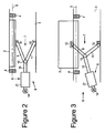
- One of these spoilers 2 is shown in Figures 2-5 .
- the wing comprises a rear spar 3 to which the spoiler 2 is pivotally attached by a pair of hinges 4.
- the spoiler pivot line 5 provided by these hinges 4 remains fixed as the spoiler is deployed.
- the spoiler 2 is rotated about the pivot line 5 by a spoiler deployment mechanism 6 comprising a scissor linkage mechanism 7 and a linear actuator 8.
- the scissor linkage mechanism 7 comprises an upper link 9 pivotally attached to the spoiler at an upper pivot 10, and a lower link 11 pivotally attached to the spar 3 at a lower pivot 12 and to the upper link 9 at a central pivot 13.
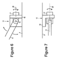
- the lower hinge mechanism at the lower pivot 12 is shown in detail in Figures 6 and 7 .
- the lower link 11 is pivotally attached to a hinge member 17 via a clevis joint which permits the link to pivot about an axis 18 as shown in Figure 6 .
- the hinge member 17 is rotatably mounted to a bracket 19 fixed to the spar 3, so that the link 11 can also rotate about an axis 20.
- the lower link 11 can rotate at the lower pivot 12 with four degrees of freedom.
- the upper hinge mechanism at the upper pivot 10 is similar to the lower hinge mechanism so that the upper link 9 can rotate about the upper pivot 10 with four degrees of freedom.
- the actuator 8 comprises a hydraulic cylinder 21 pivotally attached to a rib or other fitting (not shown) extending from the spar 3 at a proximal pivot 14, and a piston rod 15 pivotally attached to the scissor linkage mechanism at the central pivot 13.
- the cylinder 21 can be pressurised to drive the piston rod 15 out in straight line.
- the structure of the hinge mechanism at the central pivot 13 is shown in detail in Figure 8 .
- the piston rod 15 has a hole at its distal end.
- a pivot pin 16 passes through the hole in the rod 15 and also through axially aligned holes in the links 10, 11.
- the hinge mechanism shown in Figure 8 provides both a distal pivot between the actuator and the scissor linkage mechanism, and a central pivot between the scissor arms.
- the spoiler is deployed by adjusting the actuator from its contracted configuration shown in Figure 2 to its expanded configuration shown in Figure 3 , forcing the proximal and distal pivots 14,13 apart along a straight line of action. This forces the angle to open up between the upper and lower links of the scissor linkage mechanism, and the upper link 9 pushes the spoiler up into the air-stream above the wing.
- the actuator 8 rotates up about the pivot 14 to accommodate the motion of the central pivot 13 as the actuator 8 expands.
- the lower link 11 rotates about axis 18 and about axis 20 (as shown in Figures 6 and 7 ).
- the upper link 9 also rotates about two orthogonal axes at the upper hinge mechanism which attaches it to the spoiler.
- the lower pivot 12 of the scissor linkage mechanism is positioned forward of the upper pivot 10 of the scissor linkage mechanism in all positions of the spoiler.
- the pivots 13, 14 are spaced apart in a predominantly span-wise direction in both the contracted and expanded configurations of the actuator.
- the deployment mechanism takes up less space in a girth-wise direction. It also enables a large and powerful actuator 8 to be used if necessary.
- FIG. 9 An alternative configuration for the spoiler deployment mechanism is shown schematically in Figure 9 .
- This arrangement is similar to that described in Figures 2-8 , and the same reference numerals are used for equivalent features.
- the actuator 8 in its contracted state the actuator 8 is in line with the upper link 9.
- FIG. 10 A second alternative configuration is shown schematically in Figure 10 . Again, this arrangement is similar to that described in Figures 2-9 , and the same reference numerals are used for equivalent features.
- the upper link of the scissor linkage mechanism extends beyond the hinge which connects it to the lower link.
- the scissor linkage mechanism comprises an upper link 30 which is pivotally attached at its upper end to the spoiler 2 by the upper pivot 10, and pivotally attached at its lower end to the actuator piston 15 by a distal pivot 33.
- the lower link 31 of the scissor linkage mechanism is pivotally attached to the spar 3 at lower pivot 12 and to the upper link 30 at a central pivot 32.
- the central pivot 32 is not co-axial with the distal pivot 33, but rather is located on the upper link 30 between the distal pivot 33 and the upper pivot 10.
- This arrangement provides a greater mechanical advantage than the arrangement of Figure 2 .
- the benefits of the arrangement of Figure 2 are that the scissor linkage mechanism is more compact, and that the actuator is positioned in a more central position (in a girth-wise sense) so can be larger.
Landscapes
- Engineering & Computer Science (AREA)
- Aviation & Aerospace Engineering (AREA)
- Mechanical Engineering (AREA)
- Transmission Devices (AREA)
- Lighting Device Outwards From Vehicle And Optical Signal (AREA)
Claims (13)
- Flugzeugtragwerk, enthaltend:a. einen Tragflügel (1),b. eine Störklappe (2), die schwenkbar am Tragflügel (1) angebracht ist, undc. einen Störklappen-Ausfahrmechanismus (6), enthaltend:dadurch gekennzeichnet, dass der nahe (14) und der ferne (13, 33) Drehpunkt bei wenigstens einer Konfiguration des Stellantriebs (8) in einer vorwiegend der Spannweite entsprechenden Richtung beabstandet sind und dass sich das obere Verbindungsglied (9) um zwei orthogonale Achsen am oberen Gelenkmechanismus, der es an der Störklappe anfügt, drehen kann und sich das untere Verbindungsglied (11) um zwei orthogonale Achsen (18, 20) am unteren Gelenkmechanismus, der es am Tragflügel anfügt, drehen kann.i. einen Gestängemechanismus (7) mit einem oberen Verbindungsglied (9), das durch einen oberen Gelenkmechanismus schwenkbar an einem oberen Drehpunkt (10) an der Störklappe (2) angebracht ist, und einem unteren Verbindungsglied (11), das durch einen unteren Gelenkmechanismus schwenkbar an einem unteren Drehpunkt (10) am Tragflügel (1) und an einem mittleren Drehpunkt (13, 32) am oberen Verbindungsglied (10) angebracht ist, undii. einen Stellantrieb (8), der schwenkbar an einem nahen Drehpunkt (14) am Tragflügel (1) und an einem fernen Drehpunkt (13, 33) am Gestängemechanismus (7) angebracht ist, wobei der Stellantrieb (8) zwischen einer ausgefahrenen und einer eingezogenen Konfiguration einstellbar sind, so dass der Abstand zwischen dem nahen (14) und fernen (13, 33) Drehpunkt verändert wird,
- Tragwerk nach Anspruch 1, bei dem der ferne Drehpunkt (13), der den Stellantrieb am Gestängemechanismus anfügt, koaxial mit dem mittleren Drehpunkt (13) ist, der das untere Verbindungsglied (11) des Gestängemechanismus (7) an das obere Verbindungsglied (9) des Gestängemechanismus (7) anfügt.
- Tragwerk nach Anspruch 2, ferner enthaltend einen Gelenkstift (16), der durch den Stellantrieb (8) und das obere (9) und untere (11) Verbindungsglied verläuft.
- Tragwerk nach Anspruch 1, bei dem der ferne Drehpunkt (33) den Stellantrieb (8) an das obere Verbindungsglied (30) anfügt und bei dem der mittlere Drehpunkt (32) zwischen dem fernen Drehpunkt (33) und dem oberen Drehpunkt (10) angeordnet ist.
- Tragwerk nach einem der vorherigen Ansprüche, bei dem die Störklappe (2) schwenkbar an einem Störklappendrehpunkt (4), der fixiert bleibt, wenn die Störklappe ausgefahren ist, am Tragflügel (1) angefügt ist.
- Tragwerk nach einem der vorherigen Ansprüche, bei dem der untere Drehpunkt (12) fixiert bleibt, wenn die Störklappe (2) ausgefahren ist.
- Tragwerk nach einem der vorherigen Ansprüche, bei dem der Tragflügel (1) einen Hinterholm (3) enthält und die Störklappe (2) schwenkbar am Hinterholm (3) angefügt ist.
- Tragwerk nach einem der vorherigen Ansprüche, bei dem der untere Drehpunkt (12) des Gestängemechanismus (7) vor dem oberen Drehpunkt (10) des Gestängemechanismus (7) angeordnet ist.
- Tragwerk nach einem der vorherigen Ansprüche, bei dem sich der ferne Drehpunkt (13, 33) nach oben bewegt, wenn sich der Stellantrieb (8) expandiert.
- Tragwerk nach einem der vorherigen Ansprüche, bei dem sich das untere Verbindungsglied (11) mit wenigstens vier Freiheitsgraden um den unteren Drehpunkt (12) drehen kann.
- Tragwerk nach einem der vorherigen Ansprüche, bei dem sich das obere Verbindungsglied (9) mit wenigstens vier Freiheitsgraden um den oberen Drehpunkt (10) drehen kann.
- Verfahren zum Betreiben eines Tragwerks nach einem der vorherigen Ansprüche, wobei das Verfahren umfasst:a. Einstellen des Stellantriebs (8) von seiner kontrahierten Konfiguration in seine expandierte Konfiguration,b. Öffnen des Winkels zwischen dem oberen (9) und dem unteren (11) Verbindungsglied des Gestängemechanismus (7) undc. Drücken der Störklappe (2) nach oben in den Luftstrom über dem Tragflügel (1) mit dem oberen Verbindungsglied (9) des Gestängemechanismus (7).
- Verfahren nach Anspruch 12, ferner umfassend das Drehen des oberen Verbindungsglieds (9) um zwei orthogonale Achsen und Drehen des unteren Verbindungsglieds (11) um zwei orthogonale Achsen (18, 20).
Applications Claiming Priority (2)
| Application Number | Priority Date | Filing Date | Title |
|---|---|---|---|
| GBGB0808349.5A GB0808349D0 (en) | 2008-05-09 | 2008-05-09 | Spoiler deployment mechanism |
| PCT/GB2009/050432 WO2009136187A1 (en) | 2008-05-09 | 2009-04-28 | Spoiler deployment mechanism |
Publications (2)
| Publication Number | Publication Date |
|---|---|
| EP2274201A1 EP2274201A1 (de) | 2011-01-19 |
| EP2274201B1 true EP2274201B1 (de) | 2013-03-13 |
Family
ID=39570984
Family Applications (1)
| Application Number | Title | Priority Date | Filing Date |
|---|---|---|---|
| EP09742383A Not-in-force EP2274201B1 (de) | 2008-05-09 | 2009-04-28 | Ausfahrmechanismus für störklappe |
Country Status (9)
| Country | Link |
|---|---|
| US (1) | US8418954B2 (de) |
| EP (1) | EP2274201B1 (de) |
| JP (1) | JP2011519781A (de) |
| CN (1) | CN102015446A (de) |
| BR (1) | BRPI0912013A2 (de) |
| CA (1) | CA2721251A1 (de) |
| GB (1) | GB0808349D0 (de) |
| RU (1) | RU2489314C2 (de) |
| WO (1) | WO2009136187A1 (de) |
Families Citing this family (18)
| Publication number | Priority date | Publication date | Assignee | Title |
|---|---|---|---|---|
| JP5562575B2 (ja) * | 2009-04-27 | 2014-07-30 | ナブテスコ株式会社 | 航空機用アクチュエータ |
| GB201009087D0 (en) * | 2010-05-28 | 2010-07-14 | Microtecnica Actuation Technol | Actuator assembly for use in a rotor blade |
| DE102010053396B4 (de) | 2010-12-03 | 2014-12-24 | Airbus Defence and Space GmbH | Übertragung einer Steuerungskraft |
| US8998132B2 (en) * | 2011-11-30 | 2015-04-07 | Lockheed Martin Corporation | Aerodynamic wing load distribution control |
| US9193573B1 (en) * | 2012-05-11 | 2015-11-24 | The Boeing Company | Process for measuring and controlling extension of scissor linkage systems |
| US10272958B2 (en) | 2015-06-07 | 2019-04-30 | RennKit LLC | Spoiler wing extension and retraction system |
| US10563615B2 (en) | 2016-05-09 | 2020-02-18 | Mra Systems, Llc | Gas turbine engine with thrust reverser assembly and method of operating |
| EP3461745B1 (de) * | 2017-09-28 | 2021-10-27 | Hamilton Sundstrand Corporation | Auslösemechanismus für staudruckturbinenaktuator |
| US11352123B2 (en) | 2018-06-28 | 2022-06-07 | Lucas Kai-Luen Hung | Wing assembly for a high endurance aircraft |
| CN111301664A (zh) * | 2019-12-11 | 2020-06-19 | 贵州贵航飞机设计研究所 | 一种张开式翼尖减速板的驱动方法 |
| GB2590620A (en) | 2019-12-20 | 2021-07-07 | Airbus Operations Ltd | Spoiler actuation apparatus for moving an aircraft spoiler |
| US11548616B1 (en) | 2020-03-02 | 2023-01-10 | Lucas Kai-Luen Hung | Split-flap wing assembly for a high endurance aircraft |
| GB2600742B (en) * | 2020-11-09 | 2023-01-04 | Airbus Operations Ltd | Aircraft spoiler and actuation apparatus |
| CN112744300B (zh) * | 2021-02-22 | 2022-06-10 | 东风商用车有限公司 | 一种电动调节顶扰流板系统及卡车 |
| US11673646B2 (en) | 2021-04-07 | 2023-06-13 | The Boeing Company | Spoiler actuation systems and methods for aircraft |
| GB2624677A (en) | 2022-11-25 | 2024-05-29 | Airbus Operations Ltd | An aircraft control surface deployment system |
| GB2626560A (en) * | 2023-01-26 | 2024-07-31 | Airbus Operations Ltd | Spoiler |
| CN119611831A (zh) * | 2024-12-30 | 2025-03-14 | 彩虹无人机科技有限公司 | 一种无人机内嵌式阻力舵运动机构及机翼 |
Family Cites Families (46)
| Publication number | Priority date | Publication date | Assignee | Title |
|---|---|---|---|---|
| USRE20075E (en) * | 1936-08-25 | Airplane wing constructhw | ||
| US2041688A (en) * | 1934-07-30 | 1936-05-26 | George E Barnhart | Airplane construction |
| GB517422A (en) | 1938-07-19 | 1940-01-30 | Westland Aircraft Ltd | Improvements in or relating to aircraft |
| DE705499C (de) * | 1939-03-04 | 1941-04-30 | Messerschmitt A G | Gestaenge zum Ein- und Ausfahren einer Bremsflaeche an Flugzeugtragflaechen |
| DE737445C (de) * | 1939-11-17 | 1943-07-14 | Arado Flugzeugwerke G M B H | Aus senkrecht oder nahezu senkrecht aus dem Tragfluegel ausfahrbaren, rechenartigen Unterbrechern bestehende Sturzflugbremse fuer Flugzeuge |
| FR877353A (fr) * | 1940-12-16 | 1942-12-04 | Messerschmitt Boelkow Blohm | Frein de piqué pour avions, composé de surfaces perturbatrices orientables à peu près perpendiculairement au vent relatif |
| GB585564A (en) | 1945-03-02 | 1947-02-11 | Blackburn Aircraft Ltd | Improvements in or relating to aircraft |
| US2973925A (en) | 1958-03-24 | 1961-03-07 | Lockheed Aircraft Corp | Aerodynamically automatic airfoil slat mechanism |
| GB870689A (en) | 1958-05-26 | 1961-06-14 | Waclaw Czerwinski | Aircraft control surface actuating mechanism |
| US3089666A (en) * | 1961-04-13 | 1963-05-14 | Boeing Co | Airplane having changeable thrust direction |
| US3908842A (en) * | 1973-05-18 | 1975-09-30 | William Place | Tow truck |
| US4019781A (en) * | 1975-11-10 | 1977-04-26 | Ray Louis M | Hydraulic hoist for pickup bed |
| US4120470A (en) * | 1976-09-28 | 1978-10-17 | The Boeing Company | Efficient trailing edge system for an aircraft wing |
| US4100850A (en) * | 1976-12-10 | 1978-07-18 | Broan Manufacturing Co., Inc. | Drive mechanism for trash compactors |
| US4444368A (en) * | 1981-10-30 | 1984-04-24 | The United States Of America As Represented By The Administrator Of The National Aeronautics And Space Administration | Slotted variable camber flap |
| US4470569A (en) * | 1981-12-28 | 1984-09-11 | Mcdonnell Douglas Corporation | Locking, redundant slat drive mechanism |
| DE3280226D1 (de) * | 1982-09-29 | 1990-09-13 | Boeing Co | Tuervorrichtung fuer schubumkehrblockierung. |
| US4553721A (en) * | 1983-08-05 | 1985-11-19 | Lockheed Corporation | Spoiler device for attachment to a leading edge slat |
| DE3702294C1 (de) | 1987-01-27 | 1988-04-14 | Messerschmitt Boelkow Blohm | Stelleinrichtung fuer Tragflaechenklappen von Flugzeugen |
| GB8814865D0 (en) * | 1988-06-22 | 1988-07-27 | Bridport Aviat Products Ltd | Safety visor for overhead luggage bin of passenger aircraft |
| US4930598A (en) * | 1988-07-25 | 1990-06-05 | 501 Sky Climber, Inc. | Scissors lift apparatus |
| GB8915487D0 (en) * | 1989-07-06 | 1989-08-23 | Short Brothers Plc | A flap assembly |
| US5092542A (en) * | 1991-02-19 | 1992-03-03 | Teleflex Incorporated | Ordnance ejector system for an aircraft |
| US5308357A (en) * | 1992-08-21 | 1994-05-03 | Microsurge, Inc. | Handle mechanism for manual instruments |
| US5487216A (en) * | 1994-01-13 | 1996-01-30 | Ethicon, Inc. | Control system for an automatic needle-suture assembly and packaging machine |
| US5501698A (en) * | 1994-02-14 | 1996-03-26 | Heartport, Inc. | Endoscopic microsurgical instruments and methods |
| ES2136475B1 (es) * | 1994-05-20 | 2000-05-16 | Sener Ing & Sist | Perfeccionamientos en toberas axisimetricas de geometria variable y orientacion del flujo destinadas a propulsores de turbina de gas. |
| US6097978A (en) * | 1997-07-03 | 2000-08-01 | Medtronic Inc. | Measurement confirmation devices and methods for fluoroscopically directed surgery |
| US6010097A (en) * | 1997-10-16 | 2000-01-04 | Northrop Grumman Corporation | Scissor linkage type slotted flap mechanism |
| US6224146B1 (en) * | 1998-11-09 | 2001-05-01 | Asc Incorporated | Spoiler sunroof mechanism |
| US6491261B1 (en) * | 2000-04-17 | 2002-12-10 | The United States Of America As Represented By The Secretary Of The Air Force | Wing mounted aircraft yaw control device |
| FR2815933B1 (fr) * | 2000-10-26 | 2003-01-24 | Eads Airbus Sa | Organe et dispositif de transmission d'efforts radiaux entre des regions centrale et d'extremite de cet organe |
| US6808194B2 (en) * | 2002-05-17 | 2004-10-26 | Floyd G. Martin | Pivot linkage for truck recovery unit |
| FR2840877B1 (fr) * | 2002-06-13 | 2004-08-06 | Airbus France | Dispositif d'articulation d'un volet sur une surface aerodynamique d'aeronef |
| DE10328717B3 (de) * | 2003-06-25 | 2004-12-02 | Eads Deutschland Gmbh | Betätigungseinrichtung für eine an der Hinterkante des Tragflügels eines Flugzeugs angeordnete Ruderklappe |
| US20050165429A1 (en) * | 2004-01-23 | 2005-07-28 | Peter Douglas | Surgical clamp possessing a combined parallel and scissor style clamp head |
| US7097148B2 (en) * | 2004-07-21 | 2006-08-29 | Battelle Energy Alliance, Llc | Scissor thrust valve actuator |
| US7338018B2 (en) * | 2005-02-04 | 2008-03-04 | The Boeing Company | Systems and methods for controlling aircraft flaps and spoilers |
| US8011617B2 (en) * | 2005-06-17 | 2011-09-06 | Curry James M | Compact cargo lift for commerical aircraft |
| DE102005044549B4 (de) | 2005-09-17 | 2008-04-17 | Eads Deutschland Gmbh | Flugzeugflügel mit ausfahrbarer Nasenklappe |
| US7841829B2 (en) * | 2006-11-15 | 2010-11-30 | Sikorsky Aircraft Corporation | Rotor system with pitch flap coupling |
| DE102006059724B4 (de) * | 2006-12-18 | 2011-03-17 | Hs Genion Gmbh | Luftleitvorrichtung für ein Fahrzeug |
| CA2682680C (en) * | 2007-04-24 | 2015-11-03 | Airbus Operations Gmbh | Aircraft |
| US8104710B2 (en) * | 2007-04-25 | 2012-01-31 | Goodrich Actuation Systems Limited | Actuator arrangement |
| GB0708334D0 (en) * | 2007-04-30 | 2007-06-06 | Airbus Uk Ltd | Method and apparatus for deploying an auxiliary airfoil |
| GB0722415D0 (en) * | 2007-11-15 | 2007-12-27 | Airbus Uk Ltd | Aircraft wing and flap deployment system |
-
2008
- 2008-05-09 GB GBGB0808349.5A patent/GB0808349D0/en not_active Ceased
-
2009
- 2009-04-28 RU RU2010148409/11A patent/RU2489314C2/ru not_active IP Right Cessation
- 2009-04-28 CA CA2721251A patent/CA2721251A1/en not_active Abandoned
- 2009-04-28 EP EP09742383A patent/EP2274201B1/de not_active Not-in-force
- 2009-04-28 CN CN2009801162903A patent/CN102015446A/zh active Pending
- 2009-04-28 BR BRPI0912013A patent/BRPI0912013A2/pt not_active IP Right Cessation
- 2009-04-28 JP JP2011507994A patent/JP2011519781A/ja active Pending
- 2009-04-28 US US12/936,750 patent/US8418954B2/en not_active Expired - Fee Related
- 2009-04-28 WO PCT/GB2009/050432 patent/WO2009136187A1/en not_active Ceased
Also Published As
| Publication number | Publication date |
|---|---|
| RU2489314C2 (ru) | 2013-08-10 |
| US8418954B2 (en) | 2013-04-16 |
| WO2009136187A1 (en) | 2009-11-12 |
| CN102015446A (zh) | 2011-04-13 |
| BRPI0912013A2 (pt) | 2015-10-06 |
| RU2010148409A (ru) | 2012-06-20 |
| CA2721251A1 (en) | 2009-11-12 |
| EP2274201A1 (de) | 2011-01-19 |
| GB0808349D0 (en) | 2008-06-18 |
| JP2011519781A (ja) | 2011-07-14 |
| US20110031347A1 (en) | 2011-02-10 |
Similar Documents
| Publication | Publication Date | Title |
|---|---|---|
| US8418954B2 (en) | Spoiler deployment mechanism | |
| CN110435872B (zh) | 飞行器的机翼 | |
| EP1607324B1 (de) | Vorflügel für ein Flugzeug und entsprechende Verfahren | |
| US5836550A (en) | Mechanism for streamwise fowler deployment of the wing trailing or leading edge | |
| RU2695253C1 (ru) | Заднее крыло транспортного средства с регулируемым сечением и выдвижным щитком (варианты) | |
| JP5284794B2 (ja) | 航空機用の引き込み可能な揚力ブレード | |
| US8070106B2 (en) | Aircraft wing and flap deployment system | |
| RU2438927C2 (ru) | Увеличивающая подъемную силу крыла система для летательного аппарата | |
| CN109789920B (zh) | 对飞行器上的多功能后缘操纵面进行驱动和引导的系统 | |
| CA2992561C (en) | Load-resistant spoiler mechanism for vehicle | |
| CA2727828C (en) | Slat assembly | |
| CA2742167C (en) | Landing gear bay door with double hook mechanism | |
| CN103010455A (zh) | 具有提供多种巡航位置的紧凑大福勒运动的飞行器襟翼机构 | |
| US4202519A (en) | Airfoil leading edge slat apparatus | |
| EP3461738B1 (de) | Fowler-klappenbetätigungsvorrichtung und zugehörige verfahren | |
| EP3434583B1 (de) | Gelenkanordnungen zum einziehen von flugzeugklappenträgerverkleidungen und zugehörige verfahren | |
| US11214354B2 (en) | Control surface actuation mechanism | |
| US11161595B2 (en) | Wing flap mechanism for high fowler, drooping spoilers and high efficiency | |
| EP4269233B1 (de) | Flügel für ein flugzeug | |
| WO2001056878A1 (en) | Landing gear doors | |
| CN119611831A (zh) | 一种无人机内嵌式阻力舵运动机构及机翼 |
Legal Events
| Date | Code | Title | Description |
|---|---|---|---|
| PUAI | Public reference made under article 153(3) epc to a published international application that has entered the european phase |
Free format text: ORIGINAL CODE: 0009012 |
|
| 17P | Request for examination filed |
Effective date: 20101101 |
|
| AK | Designated contracting states |
Kind code of ref document: A1 Designated state(s): AT BE BG CH CY CZ DE DK EE ES FI FR GB GR HR HU IE IS IT LI LT LU LV MC MK MT NL NO PL PT RO SE SI SK TR |
|
| AX | Request for extension of the european patent |
Extension state: AL BA RS |
|
| DAX | Request for extension of the european patent (deleted) | ||
| GRAP | Despatch of communication of intention to grant a patent |
Free format text: ORIGINAL CODE: EPIDOSNIGR1 |
|
| GRAP | Despatch of communication of intention to grant a patent |
Free format text: ORIGINAL CODE: EPIDOSNIGR1 |
|
| GRAS | Grant fee paid |
Free format text: ORIGINAL CODE: EPIDOSNIGR3 |
|
| GRAA | (expected) grant |
Free format text: ORIGINAL CODE: 0009210 |
|
| AK | Designated contracting states |
Kind code of ref document: B1 Designated state(s): AT BE BG CH CY CZ DE DK EE ES FI FR GB GR HR HU IE IS IT LI LT LU LV MC MK MT NL NO PL PT RO SE SI SK TR |
|
| REG | Reference to a national code |
Ref country code: GB Ref legal event code: FG4D |
|
| REG | Reference to a national code |
Ref country code: AT Ref legal event code: REF Ref document number: 600637 Country of ref document: AT Kind code of ref document: T Effective date: 20130315 Ref country code: CH Ref legal event code: EP |
|
| REG | Reference to a national code |
Ref country code: IE Ref legal event code: FG4D |
|
| REG | Reference to a national code |
Ref country code: DE Ref legal event code: R096 Ref document number: 602009013912 Country of ref document: DE Effective date: 20130508 |
|
| PG25 | Lapsed in a contracting state [announced via postgrant information from national office to epo] |
Ref country code: LT Free format text: LAPSE BECAUSE OF FAILURE TO SUBMIT A TRANSLATION OF THE DESCRIPTION OR TO PAY THE FEE WITHIN THE PRESCRIBED TIME-LIMIT Effective date: 20130313 Ref country code: NO Free format text: LAPSE BECAUSE OF FAILURE TO SUBMIT A TRANSLATION OF THE DESCRIPTION OR TO PAY THE FEE WITHIN THE PRESCRIBED TIME-LIMIT Effective date: 20130613 Ref country code: SE Free format text: LAPSE BECAUSE OF FAILURE TO SUBMIT A TRANSLATION OF THE DESCRIPTION OR TO PAY THE FEE WITHIN THE PRESCRIBED TIME-LIMIT Effective date: 20130313 Ref country code: BG Free format text: LAPSE BECAUSE OF FAILURE TO SUBMIT A TRANSLATION OF THE DESCRIPTION OR TO PAY THE FEE WITHIN THE PRESCRIBED TIME-LIMIT Effective date: 20130613 Ref country code: ES Free format text: LAPSE BECAUSE OF FAILURE TO SUBMIT A TRANSLATION OF THE DESCRIPTION OR TO PAY THE FEE WITHIN THE PRESCRIBED TIME-LIMIT Effective date: 20130624 |
|
| REG | Reference to a national code |
Ref country code: AT Ref legal event code: MK05 Ref document number: 600637 Country of ref document: AT Kind code of ref document: T Effective date: 20130313 |
|
| REG | Reference to a national code |
Ref country code: NL Ref legal event code: VDEP Effective date: 20130313 |
|
| REG | Reference to a national code |
Ref country code: LT Ref legal event code: MG4D |
|
| PG25 | Lapsed in a contracting state [announced via postgrant information from national office to epo] |
Ref country code: GR Free format text: LAPSE BECAUSE OF FAILURE TO SUBMIT A TRANSLATION OF THE DESCRIPTION OR TO PAY THE FEE WITHIN THE PRESCRIBED TIME-LIMIT Effective date: 20130614 Ref country code: SI Free format text: LAPSE BECAUSE OF FAILURE TO SUBMIT A TRANSLATION OF THE DESCRIPTION OR TO PAY THE FEE WITHIN THE PRESCRIBED TIME-LIMIT Effective date: 20130313 Ref country code: LV Free format text: LAPSE BECAUSE OF FAILURE TO SUBMIT A TRANSLATION OF THE DESCRIPTION OR TO PAY THE FEE WITHIN THE PRESCRIBED TIME-LIMIT Effective date: 20130313 Ref country code: FI Free format text: LAPSE BECAUSE OF FAILURE TO SUBMIT A TRANSLATION OF THE DESCRIPTION OR TO PAY THE FEE WITHIN THE PRESCRIBED TIME-LIMIT Effective date: 20130313 |
|
| PG25 | Lapsed in a contracting state [announced via postgrant information from national office to epo] |
Ref country code: HR Free format text: LAPSE BECAUSE OF FAILURE TO SUBMIT A TRANSLATION OF THE DESCRIPTION OR TO PAY THE FEE WITHIN THE PRESCRIBED TIME-LIMIT Effective date: 20130313 Ref country code: BE Free format text: LAPSE BECAUSE OF FAILURE TO SUBMIT A TRANSLATION OF THE DESCRIPTION OR TO PAY THE FEE WITHIN THE PRESCRIBED TIME-LIMIT Effective date: 20130313 |
|
| PG25 | Lapsed in a contracting state [announced via postgrant information from national office to epo] |
Ref country code: SK Free format text: LAPSE BECAUSE OF FAILURE TO SUBMIT A TRANSLATION OF THE DESCRIPTION OR TO PAY THE FEE WITHIN THE PRESCRIBED TIME-LIMIT Effective date: 20130313 Ref country code: PT Free format text: LAPSE BECAUSE OF FAILURE TO SUBMIT A TRANSLATION OF THE DESCRIPTION OR TO PAY THE FEE WITHIN THE PRESCRIBED TIME-LIMIT Effective date: 20130715 Ref country code: RO Free format text: LAPSE BECAUSE OF FAILURE TO SUBMIT A TRANSLATION OF THE DESCRIPTION OR TO PAY THE FEE WITHIN THE PRESCRIBED TIME-LIMIT Effective date: 20130313 Ref country code: AT Free format text: LAPSE BECAUSE OF FAILURE TO SUBMIT A TRANSLATION OF THE DESCRIPTION OR TO PAY THE FEE WITHIN THE PRESCRIBED TIME-LIMIT Effective date: 20130313 Ref country code: IS Free format text: LAPSE BECAUSE OF FAILURE TO SUBMIT A TRANSLATION OF THE DESCRIPTION OR TO PAY THE FEE WITHIN THE PRESCRIBED TIME-LIMIT Effective date: 20130713 Ref country code: CZ Free format text: LAPSE BECAUSE OF FAILURE TO SUBMIT A TRANSLATION OF THE DESCRIPTION OR TO PAY THE FEE WITHIN THE PRESCRIBED TIME-LIMIT Effective date: 20130313 Ref country code: NL Free format text: LAPSE BECAUSE OF FAILURE TO SUBMIT A TRANSLATION OF THE DESCRIPTION OR TO PAY THE FEE WITHIN THE PRESCRIBED TIME-LIMIT Effective date: 20130313 Ref country code: EE Free format text: LAPSE BECAUSE OF FAILURE TO SUBMIT A TRANSLATION OF THE DESCRIPTION OR TO PAY THE FEE WITHIN THE PRESCRIBED TIME-LIMIT Effective date: 20130313 |
|
| PG25 | Lapsed in a contracting state [announced via postgrant information from national office to epo] |
Ref country code: CY Free format text: LAPSE BECAUSE OF FAILURE TO SUBMIT A TRANSLATION OF THE DESCRIPTION OR TO PAY THE FEE WITHIN THE PRESCRIBED TIME-LIMIT Effective date: 20130313 Ref country code: PL Free format text: LAPSE BECAUSE OF FAILURE TO SUBMIT A TRANSLATION OF THE DESCRIPTION OR TO PAY THE FEE WITHIN THE PRESCRIBED TIME-LIMIT Effective date: 20130313 |
|
| REG | Reference to a national code |
Ref country code: CH Ref legal event code: PL |
|
| PG25 | Lapsed in a contracting state [announced via postgrant information from national office to epo] |
Ref country code: MC Free format text: LAPSE BECAUSE OF FAILURE TO SUBMIT A TRANSLATION OF THE DESCRIPTION OR TO PAY THE FEE WITHIN THE PRESCRIBED TIME-LIMIT Effective date: 20130313 |
|
| PLBE | No opposition filed within time limit |
Free format text: ORIGINAL CODE: 0009261 |
|
| STAA | Information on the status of an ep patent application or granted ep patent |
Free format text: STATUS: NO OPPOSITION FILED WITHIN TIME LIMIT |
|
| REG | Reference to a national code |
Ref country code: IE Ref legal event code: MM4A |
|
| PG25 | Lapsed in a contracting state [announced via postgrant information from national office to epo] |
Ref country code: DK Free format text: LAPSE BECAUSE OF FAILURE TO SUBMIT A TRANSLATION OF THE DESCRIPTION OR TO PAY THE FEE WITHIN THE PRESCRIBED TIME-LIMIT Effective date: 20130313 Ref country code: LI Free format text: LAPSE BECAUSE OF NON-PAYMENT OF DUE FEES Effective date: 20130430 Ref country code: CH Free format text: LAPSE BECAUSE OF NON-PAYMENT OF DUE FEES Effective date: 20130430 |
|
| 26N | No opposition filed |
Effective date: 20131216 |
|
| PG25 | Lapsed in a contracting state [announced via postgrant information from national office to epo] |
Ref country code: IT Free format text: LAPSE BECAUSE OF FAILURE TO SUBMIT A TRANSLATION OF THE DESCRIPTION OR TO PAY THE FEE WITHIN THE PRESCRIBED TIME-LIMIT Effective date: 20130313 |
|
| REG | Reference to a national code |
Ref country code: DE Ref legal event code: R097 Ref document number: 602009013912 Country of ref document: DE Effective date: 20131216 |
|
| PG25 | Lapsed in a contracting state [announced via postgrant information from national office to epo] |
Ref country code: IE Free format text: LAPSE BECAUSE OF NON-PAYMENT OF DUE FEES Effective date: 20130428 |
|
| REG | Reference to a national code |
Ref country code: DE Ref legal event code: R082 Ref document number: 602009013912 Country of ref document: DE Representative=s name: TETZNER & PARTNER MBB PATENT- UND RECHTSANWAEL, DE |
|
| PG25 | Lapsed in a contracting state [announced via postgrant information from national office to epo] |
Ref country code: MT Free format text: LAPSE BECAUSE OF FAILURE TO SUBMIT A TRANSLATION OF THE DESCRIPTION OR TO PAY THE FEE WITHIN THE PRESCRIBED TIME-LIMIT Effective date: 20130313 |
|
| REG | Reference to a national code |
Ref country code: FR Ref legal event code: PLFP Year of fee payment: 7 |
|
| PG25 | Lapsed in a contracting state [announced via postgrant information from national office to epo] |
Ref country code: TR Free format text: LAPSE BECAUSE OF FAILURE TO SUBMIT A TRANSLATION OF THE DESCRIPTION OR TO PAY THE FEE WITHIN THE PRESCRIBED TIME-LIMIT Effective date: 20130313 |
|
| PG25 | Lapsed in a contracting state [announced via postgrant information from national office to epo] |
Ref country code: HU Free format text: LAPSE BECAUSE OF FAILURE TO SUBMIT A TRANSLATION OF THE DESCRIPTION OR TO PAY THE FEE WITHIN THE PRESCRIBED TIME-LIMIT; INVALID AB INITIO Effective date: 20090428 Ref country code: LU Free format text: LAPSE BECAUSE OF NON-PAYMENT OF DUE FEES Effective date: 20130428 Ref country code: MK Free format text: LAPSE BECAUSE OF FAILURE TO SUBMIT A TRANSLATION OF THE DESCRIPTION OR TO PAY THE FEE WITHIN THE PRESCRIBED TIME-LIMIT Effective date: 20130313 |
|
| PGFP | Annual fee paid to national office [announced via postgrant information from national office to epo] |
Ref country code: DE Payment date: 20150421 Year of fee payment: 7 Ref country code: GB Payment date: 20150420 Year of fee payment: 7 |
|
| PGFP | Annual fee paid to national office [announced via postgrant information from national office to epo] |
Ref country code: FR Payment date: 20150421 Year of fee payment: 7 |
|
| REG | Reference to a national code |
Ref country code: DE Ref legal event code: R119 Ref document number: 602009013912 Country of ref document: DE |
|
| GBPC | Gb: european patent ceased through non-payment of renewal fee |
Effective date: 20160428 |
|
| REG | Reference to a national code |
Ref country code: FR Ref legal event code: ST Effective date: 20161230 |
|
| PG25 | Lapsed in a contracting state [announced via postgrant information from national office to epo] |
Ref country code: FR Free format text: LAPSE BECAUSE OF NON-PAYMENT OF DUE FEES Effective date: 20160502 Ref country code: DE Free format text: LAPSE BECAUSE OF NON-PAYMENT OF DUE FEES Effective date: 20161101 Ref country code: GB Free format text: LAPSE BECAUSE OF NON-PAYMENT OF DUE FEES Effective date: 20160428 |