EP2274468B1 - Haushaltsstandgerät - Google Patents
Haushaltsstandgerät Download PDFInfo
- Publication number
- EP2274468B1 EP2274468B1 EP09727889A EP09727889A EP2274468B1 EP 2274468 B1 EP2274468 B1 EP 2274468B1 EP 09727889 A EP09727889 A EP 09727889A EP 09727889 A EP09727889 A EP 09727889A EP 2274468 B1 EP2274468 B1 EP 2274468B1
- Authority
- EP
- European Patent Office
- Prior art keywords
- domestic
- appliance according
- mounting
- standing appliance
- mounting aid
- Prior art date
- Legal status (The legal status is an assumption and is not a legal conclusion. Google has not performed a legal analysis and makes no representation as to the accuracy of the status listed.)
- Active
Links
Images

Classifications
-
- D—TEXTILES; PAPER
- D06—TREATMENT OF TEXTILES OR THE LIKE; LAUNDERING; FLEXIBLE MATERIALS NOT OTHERWISE PROVIDED FOR
- D06F—LAUNDERING, DRYING, IRONING, PRESSING OR FOLDING TEXTILE ARTICLES
- D06F39/00—Details of washing machines not specific to a single type of machines covered by groups D06F9/00 - D06F27/00
- D06F39/001—Arrangements for transporting, moving, or setting washing machines; Protective arrangements for use during transport
-
- A—HUMAN NECESSITIES
- A47—FURNITURE; DOMESTIC ARTICLES OR APPLIANCES; COFFEE MILLS; SPICE MILLS; SUCTION CLEANERS IN GENERAL
- A47L—DOMESTIC WASHING OR CLEANING; SUCTION CLEANERS IN GENERAL
- A47L15/00—Washing or rinsing machines for crockery or tableware
- A47L15/42—Details
- A47L15/4214—Water supply, recirculation or discharge arrangements; Devices therefor
- A47L15/4217—Fittings for water supply, e.g. valves or plumbing means to connect to cold or warm water lines, aquastops
-
- A—HUMAN NECESSITIES
- A47—FURNITURE; DOMESTIC ARTICLES OR APPLIANCES; COFFEE MILLS; SPICE MILLS; SUCTION CLEANERS IN GENERAL
- A47L—DOMESTIC WASHING OR CLEANING; SUCTION CLEANERS IN GENERAL
- A47L15/00—Washing or rinsing machines for crockery or tableware
- A47L15/42—Details
- A47L15/4214—Water supply, recirculation or discharge arrangements; Devices therefor
- A47L15/4223—Devices for water discharge, e.g. devices to prevent siphoning, non-return valves
-
- A—HUMAN NECESSITIES
- A47—FURNITURE; DOMESTIC ARTICLES OR APPLIANCES; COFFEE MILLS; SPICE MILLS; SUCTION CLEANERS IN GENERAL
- A47L—DOMESTIC WASHING OR CLEANING; SUCTION CLEANERS IN GENERAL
- A47L15/00—Washing or rinsing machines for crockery or tableware
- A47L15/42—Details
- A47L15/4251—Details of the casing
- A47L15/427—Arrangements for setting the machine, e.g. anti-tip devices therefor, fixing of integrated machines
Definitions
- the invention relates to a household appliance, in particular a dishwasher, according to the preamble of claim 1.
- Household appliances such as Dishwashers, washing machines, dryers, refrigerators or ovens are built-in or as a stand alone with separate, each fulfill a function assembly aids, such as a hose holder for water-bearing appliances such as dishwashers or washing machines, instructions for use, a tilt protection part or a mounting bracket for base units , delivered to the end customer.
- a function assembly aids such as a hose holder for water-bearing appliances such as dishwashers or washing machines, instructions for use, a tilt protection part or a mounting bracket for base units , delivered to the end customer.
- the number of mounting aids to be supplied increases.
- the DE 197 48 703 A1 discloses a water-bearing household appliance with a holding element for water hoses, which are connected before operation with a water supply or water disposal. While the holding element serves to fix the hoses during the transport of the household machine, it can be used according to the invention during operation of the household appliance for an alternative function fulfillment, for example for attaching the hoses to a sink or bath rim.
- the invention relates to a household appliance, in particular a dishwasher, at least comprising a mounting aid.
- the solution of the object of the invention is characterized in that the assembly aid has at least two functional parts, which are formed by means of at least one separation point separable from each other.
- the number of using the household appliance delivered items is thereby advantageously reduced in a surprisingly simple manner.
- the separation points may be formed as, for example, as releasable snap connections.
- the at least one separation point is designed as a predetermined breaking or bending point. If necessary, the respective functional part can be moved from its assembly position into a position of use separated from the assembly aid. For this purpose, the functional part is separated at the separation point of the mounting aid.
- the mounting aid is formed of the same material and in one piece. This makes it possible to produce the mounting aid without mounting the functions associated sections of the mounting aid. In addition, so more functional parts can be captively formed on the hose holding member.
- a functional part is designed as a hose holder.
- the functional part designed as a hose holder allows for installation or assembly of a water-conducting household appliance such. a dishwasher or washing machine positioning of inlet and / or drain hose or formation of a siphon.
- a functional part is designed as a mounting bracket for securing the household appliance from being pulled out of its installation position.
- the fastener secures in its position of use a household appliance designed as a household appliance, such. Dishwashers, refrigerators or ovens before pulling out of its installed position. The operation of the fastener is known as such.
- a functional part is designed as a tilt protection part.
- the anti-tip part may be in its, separated from the mounting tool position of use adjacent to a household appliance wall and at the same time in engagement with the household appliance.
- Kippschsers The function of Kipp Klischsers is well known. It should be a tilting moment counteract that can be applied to the household appliance such as a dishwasher or a refrigerator when the household appliance door.
- the anti-tip part may preferably be L-shaped with a securing leg and a mounting leg.
- the securing leg can be in a position of use in engagement with the feed container of the household appliance.
- the mounting leg can be used for wall mounting.
- an additional mounting flange for screwing with the wall can be formed on the mounting leg.
- the securing leg of Kipp Rundsmaschines mounting technology is easy to bring into engagement with the household appliance.
- the securing leg can have a downwardly pointing bulge into which a rear connecting flange of the household appliance charging container can be inserted by means of a corresponding oblique position of the household appliance. In the end position of the connecting flange protrudes positively into the bulge of the securing leg.
- a functional part is designed as a hook for attaching additional parts in order to be able to hook in appropriate additional parts.
- the assembly aid may preferably have at least a first attachment point for mounting on the household appliance.
- This attachment point can be, for example, a hook portion, with which the mounting aid can be hung on a connecting flange of a charging container of the household appliance.
- the above-mentioned first attachment point of the mounting tool may be provided on a functional part.
- the mounting tool may also preferably have a second attachment point for a household appliance independent wall mounting.
- the second attachment point can be used when the functional part has been separated from the body of the assembly tool. In this case, the above-mentioned first attachment point separated together with the functional part of the body of the mounting tool.
- the main body of the hose holding element may preferably be a base plate, on the narrow sides of which preferably functional elements are formed.
- the functional elements and the base plate can merge flush with each other.
- the base plate together with the functional elements provide a common abutment surface, which can be brought, for example, into contact with a rear wall of the charging container of the household appliance.
- bulges may be provided on the securing leg of the anti-tip device and preferably offset in relation to one another in a depth direction.
- the assembly tool can therefore be used for differently sized feed container.
- the first or the second attachment point can be used.
- the assembly aid is a plastic injection-molded part.
- the injection molding tools are to be designed such that in the limited injection molding chamber of the base body is moldable together with the functional parts integrated therewith.
- the assembly aid is a plastic injection molded part.
- the mounting aid is arranged on the outside of the housing of the household appliance, for example. On a rear wall of the housing of the household appliance.
- the number of functional parts of the mounting aid is equal to or higher than the number of separation points. That is, the assembly tool can be separated by means of the separation points into a number of elements, wherein at least one of the elements associated with more than one functional part is. This allows a particularly simple construction of the assembly aid, since the number of separation points is minimized.
- the invention includes an assembly aid for a household appliance according to the invention.
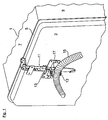
- FIG. 1 is shown in a perspective partial view of the back of a washing container 1 a dishwasher.
- the back of the washing compartment 1 is closed by a rear wall 3.
- the rear wall 3 is connected via a connecting flange 5 with a box-shaped metal jacket in combination, which forms the top wall 7 and the side walls 9 and the bottom wall of the washing compartment 1, not shown.
- the assembly aid 11 is a plastic injection-molded part and has as functional parts two hose holders 13 arranged one above the other, in each of which a water inlet hose 15 shown and a drain hose, not shown, can be held.
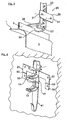
- the assembly aid 11 is in the Fig. 2 shown in isolation. Accordingly, the mounting aid 11 as a base body on a base plate 17, on the front side 18, the two tube holder 13 are formed. At its two narrow edge sides 19, a mounting bracket 20 is formed in each case as a further functional part, which is provided in the region of the edge sides 19 with a separation point 21.
- the separation point 21 is a predetermined breaking point or bending point, which may be designed as a material taper.
- the two mounting brackets 20 serve to secure the dishwasher from being pulled out of its installed position.
- the installation and operation of the mounting bracket 21 will be described later with reference to Fig. 5 described.
- the base plate 17 is vertically upwardly of the same material and integrally extended with a mounting leg 23 of an L-shaped Kipp Klischsmaschines 25, which serves as another functional part.
- the mounting leg 23 passes into an angled securing leg 27, which has formed as bulges 27 first attachment points for suspending the mounting tool 11 on the dishwasher, as shown in the Fig. 1 is shown.
- the mounting tool 11 is mounted on one of the two bulges 27 on the securing leg 26 of the anti-tip device 25.
- the mounting aid 11 is also provided with a stiffening rib 28. This extends along a longitudinal center axis of the base plate 17, the mounting leg 23 and the securing leg 26 and increases the dimensional stability of the mounting aid 11th
- the molded on the base body 17 Kippschsteil 25 can be separated at the separation point 21.
- the thus separated anti-tip part 25 is then rotated by 180 ° with its upwardly facing mounting leg 23 mounted on a wall.
- the use position of the separated Kipptechnischsers 25 is in the Fig. 3 shown.
- the mounting leg 23 additionally has a mounting flange 29 with screw holes, which are in the indicated screw 31 with a mounting wall, not shown.
- Fig. 3 is a downwardly facing recess 33 provided in the securing leg 26, in which the connecting flange 5 of the washing compartment 1 protrudes.
- the dishwasher is placed in an inclined position and poured with the connecting flange 5 in the bulge 33.
- the remaining base plate 17 of the mounting tool 11 can according to the Fig. 4 be attached to an adjacent mounting wall 35 regardless of the dishwasher.
- a fastening tab is integrally formed directly on the base plate 17 as a second attachment point 37, which is fastened via a screw 39 to the mounting wall 35.
- the inlet and outlet hoses can be held at a distance from the dishwasher on adjacent furniture walls or on the kitchen wall.
- a hook portion 41 is provided, which extends the base plate 17 vertically downwards.
- the hook portion 41 is formed in contrast to the other functional parts 20, 25 without intermediate separation point on the base plate 17 and is used for attaching other additional parts, such as a bag for an instruction manual.
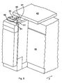
- the Fig. 5 shows a mounting situation of a dishwasher designed as a base unit.
- the dishwasher is pulled in a depth direction y halfway from a sub-space, which is bounded by an upper-side worktop 43 and an adjacent piece of furniture 45.
- a rectangular receiving element 47 is provided in the front corner region, of which one of the two fastening angles 20 is shown at a distance.
- the fastening angle shown 20 has two downwardly projecting insertion tabs 49, which are used in arrow directions in receiving slots 51 of the receiving element 47. Subsequently, the dishwasher is pushed in the Bautiefencardi y in its installed position, so that the mounting bracket 20 of the underside of the worktop 43 is opposite and can be screwed with this.
Landscapes
- Engineering & Computer Science (AREA)
- Water Supply & Treatment (AREA)
- Textile Engineering (AREA)
- Washing And Drying Of Tableware (AREA)
- Combinations Of Kitchen Furniture (AREA)
- Liquid Crystal Substances (AREA)
- Food-Manufacturing Devices (AREA)
Description
- Die Erfindung betrifft ein Haushaltsstandgerät, insbesondere eine Geschirrspülmaschine, nach dem Oberbegriff des Patentanspruches 1.
- Haushaltsstandgeräte wie z.B. Geschirrspülmaschinen, Waschmaschinen, Trockner, Kühlschränke oder Öfen werden als Einbau- oder als Standgeräte zusammen mit separaten, je eine Funktion erfüllenden Montagehilfen, etwa einem Schlauchhalter bei wasserführenden Haushaltsgeräten wie Geschirrspül- oder Waschmaschinen, einer Gebrauchsanweisung, einem Kippsicherungsteil oder einem Befestigungswinkel für Unterbau-Geräte, an den Endkunden ausgeliefert. Entsprechend der Vielzahl von Funktionen erhöht sich die Anzahl der mit zu liefernden Montagehilfen.
- Die
DE 197 48 703 A1 offenbart eine wasserführende Haushaltsmaschine mit einem Halteelement für Wasserschläuche, die vor dem Betrieb mit einer Wasserver- oder Wasserentsorgung verbunden werden. Während das Halteelement während des Transports der Haushaltsmaschine der Fixierung der Schläuche dient, kann es erfindungsgemäß während des Betriebes der Haushaltsmaschine zu einer alternativen Funktionserfüllung, beispielsweise zum Anhängen der Schläuche an einen Waschbecken- oder Badewannenrand, eingesetzt werden. - Es ist daher Aufgabe der Erfindung, die Anzahl der mit zu liefernden Montagehilfen zu reduzieren.
- Die Aufgabe ist durch die Merkmale des Patentanspruches 1 gelöst. Vorteilhafte Weiterbildungen der Erfindung sind in den Unteransprüchen offenbart.
- Die Erfindung geht aus von einem Haushaltsstandgerät, insbesondere einer Geschirrspülmaschine, wenigstens aufweisend ein Montagehilfsmittel.
- Die Lösung der Aufgabe der Erfindung ist dadurch gekennzeichnet, dass das Montagehilfsmittel wenigstens zwei Funktionsteile aufweist, die mittels wenigstens einer Trennstelle voneinander trennbar ausgebildet sind. Die Anzahl der mit dem Haushaltsgerät gelieferten Einzelteile ist dadurch auf überraschend einfache Weise vorteilhaft reduziert.
- Dabei können die Trennstellen als bspw. als lösbare Schnappverbindungen ausgebildet sein. Vorzugsweise ist jedoch vorgesehen, dass die wenigstens eine Trennstelle als Sollbruch- oder Biegestelle ausgebildet ist. Bei Bedarf kann das jeweilige Funktionsteil von seiner Zusammenbaulage in eine von der Montagehilfe separierte Gebrauchslage verbracht werden. Hierzu wird das Funktionsteil an der Trennstelle von der Montagehilfe abgetrennt.
- Ferner ist vorzugsweise vorgesehen, dass das Montagehilfsmittel materialeinheitlich und einstückig ausgebildet ist. Dies erlaubt es, die Montagehilfe ohne Montage der Funktionen zugeordneten Abschnitte der Montagehilfe herzustellen. Außerdem können so weitere Funktionsteile verliersicher am Schlauchhalteelement angeformt sein.
- In einer bevorzugten Ausführungsform ist vorgesehen, dass ein Funktionsteil als Schlauchhalter ausgebildet ist. Dabei erlaubt das als Schlauchhalter ausgebildete Funktionsteil bei Aufstellung bzw. Montage eines wasserführenden Haushaltsgeräts wie z.B. einer Geschirrspülmaschine oder Waschmaschine eine Positionierung von Zu- und/oder Ablaufschlauch oder Bildung eines Siphons.
- In einer weiteren, bevorzugten Ausführungsform ist vorgesehen, dass ein Funktionsteil als Befestigungswinkel zur Sicherung des Haushaltsgerätes vor einem Herausziehen aus seiner Einbaulage ausgebildet ist. Damit sichert das Befestigungselement in seiner Gebrauchslage ein als Einbau-Haushaltsgerät ausgebildetes Haushaltsgerät, wie z.B. Geschirrspülmaschinen, Kühlschränke oder Öfen vor einem Herausziehen aus seiner Einbaulage. Die Funktionsweise des Befestigungselementes ist als solche bekannt.
- In einer weiteren, bevorzugten Ausführungsform ist vorgesehen, dass ein Funktionsteil als Kippsicherungsteil ausgebildet ist. Das Kippsicherungsteil kann in seiner, vom Montagehilfsmittel abgetrennten Gebrauchslage an einer zum Haushaltsgerät angrenzenden Wand und gleichzeitig auch in Eingriff mit dem Haushaltsgerät sein. Die Funktion des Kippsicherungsteiles ist allgemein bekannt. Es soll einem Kippmoment entgegenwirken, das bei Beaufschlagung der Haushaltsgerätetür auf das Haushaltsgerät wie z.B. einer Geschirrspülmaschine oder einem Kühlschrank aufgebracht werden kann.
- Das Kippsicherungsteil kann bevorzugt L-förmig mit einem Sicherungsschenkel und einem Montageschenkel ausgebildet sein. Der Sicherungsschenkel kann in einer Gebrauchslage in Eingriff mit dem Beschickungsbehälter des Haushaltsgerätes sein. Demgegenüber kann der Montageschenkel für eine Wandmontage eingesetzt werden. Hierzu kann am Montageschenkel ein zusätzlicher Befestigungsflansch zum Verschrauben mit der Wand angeformt sein.
- Von Vorteil ist es, wenn der Sicherungsschenkel des Kippsicherungsteiles montagetechnisch einfach in Eingriff mit dem Haushaltsgerät bringbar ist. Hierzu kann der Sicherungsschenkel eine nach unten weisende Ausbuchtung aufweisen, in die durch entsprechende Schrägstellung des Haushaltsgerätes ein rückseitiger Verbindungsflansch des Haushaltsgeräte-Beschickungsbehälter einsetzbar ist. In der Endlage ragt der Verbindungsflansch formschlüssig in die Ausbuchtung des Sicherungsschenkels ein.
- In einer weiteren, bevorzugten Ausführungsform ist vorgesehen, dass ein Funktionsteil als Haken zum Einhängen von Zusatzteilen ausgebildet ist, um entsprechende Zusatzteile einhängen zu können.
- Das Montagehilfsmittel kann vorzugsweise zumindest einen ersten Befestigungspunkt zur Halterung am Haushaltsgerät aufweisen. Dieser Befestigungspunkt kann beispielhaft ein Hakenabschnitt sein, mit dem das Montagehilfsmittel an einem Verbindungsflansch eines Beschickungsbehälters des Haushaltsgerätes eingehängt werden kann. Der oben erwähnte erste Befestigungspunkt des Montagehilfsmittels kann an einem Funktionsteil vorgesehen sein.
- Das Montagehilfsmittel kann darüber hinaus vorzugsweise einen zweiten Befestigungspunkt für eine vom Haushaltsgerät unabhängige Wandmontage aufweisen. Der zweite Befestigungspunkt kann zum Einsatz kommen, wenn das Funktionsteil vom Grundkörper des Montagehilfsmittels separiert worden ist. In diesem Fall ist der oben erwähnte erste Befestigungspunkt zusammen mit dem Funktionsteil vom Grundkörper des Montagehilfsmittels abgetrennt.
- Der Grundkörper des Schlauchhalteelementes kann vorzugsweise eine Grundplatte sein, an deren Schmalseiten vorzugsweise Funktionselemente angeformt sind. Dabei können vorzugsweise die Funktionselemente und die Grundplatte flächenbündig ineinander übergehen. Auf diese Weise stellen die Grundplatte zusammen mit den Funktionselementen eine gemeinsame Anlagefläche bereit, die beispielsweise in Kontakt mit einer Rückwand des Beschickungsbehälters des Haushaltsgerätes gebracht werden kann.
- Vorzugsweise können am Sicherungsschenkel des Kippsicherungsteiles Ausbuchtungen vorgesehen sein und vorzugsweise in einer Bautiefenrichtung versetzt zueinander angeordnet sein. Das Montagehilfsmittel kann daher für unterschiedlich dimensionierte Beschickungsbehälter eingesetzt werden. Je nach Ausführung des Beschickungsbehälters kann der erste oder der zweite Befestigungspunkt zum Einsatz kommen.
- Ferner ist vorzugsweise vorgesehen, dass das Montagehilfsmittel ein Kunststoffspritzgussteil ist. Hierzu sind die Spritzgusswerkzeuge derart auszulegen, dass in der davon begrenzten Spritzgusskammer der Grundkörper gemeinsam mit den daran integrierten Funktionsteilen formbar ist.
- Außerdem ist vorzugsweise vorgesehen, dass das Montagehilfsmittel ein Kunststoffspritzteil ist.
- Es ist ferner vorzugsweise vorgesehen, dass das Montagehilfsmittel außenseitig am Gehäuse des Haushaltsstandgeräts angeordnet ist, bspw. an einer Rückwand des Gehäuses des Haushaltsstandgeräts.
- Schließlich ist vorzugsweise vorgesehen, dass die Anzahl der Funktionsteile des Montagehilfsmittels gleich oder höher als die Anzahl der Trennstellen ist. D.h., das Montagehilfsmittel kann mittels der Trennstellen in eine Anzahl von Elementen zerlegt werden, wobei wenigstens einem der Elemente mehr als ein Funktionsteil zugeordnet ist. Dies erlaubt einen besonders einfachen Aufbau des Montagehilfsmittels, da die Anzahl der Trennstellen minimiert ist.
- Ferner gehört zur Erfindung ein Montagehilfsmittel für ein erfindungsgemäßes Haushaltsstandgerät.
- Nachfolgend ist ein Ausführungsbeispiel der Erfindung anhand der beigefügten Figuren beschrieben. Es zeigen:
- Fig. 1
- in einer perspektivischen Teilansicht die Einbaulage eines Montagehilfsmittels an der Rückwand eines Spülbehälters einer Geschirrspülmaschine;
- Fig. 2
- in perspektivischer Ansicht das Montagehilfsmittel in Alleinstellung;
- Fig. 3
- ein vom Montagehilfsmittel separiertes Kippsicherungsteil in seiner Gebrauchslage;
- Fig. 4
- einen Grundkörper des Montagehilfsmittels in seiner Gebrauchslage; und
- Fig. 5
- die Montage eines vom Grundkörper des Montagehitfsmittels separierten Befestigungselementes.
- In der
Fig. 1 ist in perspektivischer Teilansicht die Rückseite eines Spülbehälters 1 einer Geschirrspülmaschine gezeigt. Die Rückseite des Spülbehälters 1 ist durch eine Rückwand 3 geschlossen. Die Rückwand 3 ist über einen Verbindungsflansch 5 mit einem kastenförmigen Blechmantel in Verbindung, der die Deckwand 7 sowie die Seitenwände 9 und die nicht dargestellte Bodenwand des Spülbehälters 1 bildet. - Auf der Oberseite des Spülbehälters 1 ist am Verbindungsflansch 5 ein Montagehilfsmittel 11 eingehängt. Das Montagehilfsmittel 11 ist ein Kunststoffspritzgussteil und weist als Funktionsteile zwei übereinander angeordnete Schlauchhalter 13 auf, in denen jeweils ein gezeigter Wasserzulaufschlauch 15 sowie ein nicht dargestellter Ablaufschlauch gehaltert werden können.
- Das Montagehilfsmittel 11 ist in der
Fig. 2 in Alleinstellung gezeigt. Demzufolge weist das Montagehilfsmittel 11 als Grundkörper eine Grundplatte 17 auf, an deren Frontseite 18 die beiden Schlauchhalter 13 ausgebildet sind. An ihren beiden schmalen Randseiten 19 ist jeweils als weiteres Funktionsteil ein Befestigungswinkel 20 angeformt, der im Bereich der Randseiten 19 mit einer Trennstelle 21 versehen ist. Die Trennstelle 21 ist eine Sollbruch- oder -biegestelle, die als eine Materialverjüngung ausgeführt sein kann. - Die beiden Befestigungswinkel 20 dienen der Sicherung der Geschirrspülmaschine vor einem Herausziehen aus ihrer Einbaulage. Die Montage sowie die Funktionsweise der Befestigungswinkel 21 werden später anhand der
Fig. 5 beschrieben. - Wie aus der
Fig. 2 weiter hervorgeht, ist die Grundplatte 17 vertikal nach oben materialeinheitlich und einstückig mit einem Montageschenkel 23 eines L-förmigen Kippsicherungsteiles 25 verlängert, das als weiteres Funktionsteil dient. Der Montageschenkel 23 geht in einen abgewinkelten Sicherungsschenkel 27 über, der als Ausbuchtungen 27 gestaltete erste Befestigungspunkte zum Einhängen des Montagehilfsmittels 11 an der Geschirrspülmaschine aufweist, wie es in derFig. 1 gezeigt ist. Gemäß derFig. 1 ist das Montagehilfsmittel 11 über eine der beiden Ausbuchtungen 27 am Sicherungsschenkel 26 des Kippsicherungsteiles 25 eingehängt. - Das Montagehilfsmittel 11 ist außerdem mit einer Versteifungsrippe 28 versehen. Diese erstreckt sich entlang einer Längsmittelachse der Grundplatte 17, des Montageschenkels 23 und des Sicherungsschenkels 26 und erhöht die Formstabilität des Montagehilfsmittels 11.
- Bei Bedarf kann das am Grundkörper 17 angeformte Kippsicherungsteil 25 an der Trennstelle 21 abgetrennt werden. Das somit separierte Kippsicherungsteil 25 wird dann um 180° gedreht mit seinem nach oben weisenden Montageschenkel 23 an eine Wand montiert. Die Gebrauchsstellung des separierten Kippsicherungsteiles 25 ist in der
Fig. 3 gezeigt. Demzufolge weist der Montageschenkel 23 zusätzlich einen Befestigungsflansch 29 mit Schraublöchern auf, die in angedeuteter Schraubverbindung 31 mit einer nicht gezeigten Montagewand sind. - Gemäß der
Fig. 3 ist eine nach unten weisende Ausbuchtung 33 im Sicherungsschenkel 26 vorgesehen, in die der Verbindungsflansch 5 des Spülbehälters 1 einragt. Zum Einsetzen des Verbindungsflansches 5 in die Ausbuchtung 33 des Kippsicherungsteiles 25 wird die Geschirrspülmaschine in eine Schrägstellung verbracht und mit dem Verbindungsflansch 5 in die Ausbuchtung 33 eingeschenkt. - Die verbleibende Grundplatte 17 des Montagehilfsmittels 11 kann gemäß der
Fig. 4 unabhängig von der Geschirrspülmaschine an eine angrenzende Montagewand 35 befestigt werden. Hierzu ist unmittelbar an der Grundplatte 17 als ein zweiter Befestigungspunkt 37 eine Befestigungslasche angeformt, die über eine Schraubverbindung 39 an der Montagewand 35 befestigt ist. Je nach Einbauverhältnisse können daher die Zu- und Ablaufschläuche beabstandet von dem Geschirrspüler an angrenzenden Möbelwänden bzw. an der Küchenwand gehaltert werden. - Als weiteres Funktionsteil ist ein Hakenabschnitt 41 vorgesehen, der die Grundplatte 17 vertikal nach unten verlängert. Der Hakenabschnitt 41 ist im Gegensatz zu den anderen Funktionsteilen 20, 25 ohne zwischengeschaltete Trennstelle an der Grundplatte 17 angeformt und dient zum Einhängen weiterer Zusatzteile, etwa eines Beutels für eine Gebrauchsanleitung.
- Wie bereits erwähnt, ist in der
Fig. 5 die Einbaulage und die Funktionsweise der seitlich an der Grundplatte 17 angeformten Befestigungswinkel 20 beschrieben. DieFig. 5 zeigt eine Einbausituation einer als Unterbau-Gerät ausgeführten Geschirrspülmaschine. Die Geschirrspülmaschine ist in einer Bautiefenrichtung y zur Hälfte aus einem Unterbauraum herausgezogen, der von einer oberseitigen Arbeitsplatte 43 und einem benachbarten Möbelstück 45 begrenzt ist. In der freigelegten Oberseite der Geschirrspülmaschine ist im vorderen Eckbereich ein rechtwinkliges Aufnahmeelement 47 vorgesehen, von dem beabstandet eines der beiden Befestigungswinkel 20 dargestellt ist. - Wie aus der
Fig. 5 hervorgeht, weist der gezeigte Befestigungswinkel 20 zwei nach unten abragende Einführlaschen 49 auf, die in Pfeilrichtungen in Aufnahmeschlitze 51 des Aufnahmeelementes 47 eingesetzt werden. Anschließend wird die Geschirrspülmaschine in der Bautiefenrichtung y in ihre Einbauposition geschoben, so dass der Befestigungswinkel 20 der Unterseite der Arbeitsplatte 43 gegenüberliegt und mit dieser verschraubt werden kann. - Für den Fall, dass die Arbeitsplatte 43 beispielsweise aus Marmorstein gefertigt ist, ist eine Verschraubung der Befestigungswinkel 20 nicht möglich. Aus diesem Grund weisen die beiden Befestigungswinkel 20 Filmscharniere 53 auf, mit denen Schraubansätze 55 von den Befestigungswinkeln 20 abgeklappt werden können. Auf diese Weise ist es ermöglicht, die Befestigungswinkel 20, anstelle der Arbeitsplatte 43, mit seitlich angrenzenden, vertikalen Möbelwänden zu verschrauben.
-
- 1
- Spülbehälter
- 3
- Rückwand
- 5
- Verbindungsflansch
- 7
- Deckwand
- 9
- Seitenwand
- 11
- Montagehilfsmittel
- 13
- Schlauchhalter
- 15
- Zulaufschlauch
- 17
- Grundplatte
- 18
- Frontseite
- 19
- Schmale Randseiten
- 20
- Befestigungswinkel
- 21
- Trennstelle
- 23
- Montageschenkel
- 25
- Kippsicherungsteil
- 26
- Sicherungsschenkel
- 27
- Erste Befestigungspunkte
- 28
- Versteifungsrippe
- 29
- Befestigungsflansch
- 31
- Schraubverbindung
- 33
- Ausbuchtung
- 35
- Montagewand
- 37
- Befestigungslasche
- 39
- Schraubverbindung
- 41
- Hakenabschnitt
- 43
- Arbeitsplatte
- 45
- Möbelstück
- 47
- Aufnahmeelement
- 49
- Einführlaschen
- 51
- Aufnahmeschlitze
- 53
- Filmscharnier
- 55
- Schraubansätze
- y
- Bautiefenrichtung
Claims (21)
- Haushaltsstandgerät, insbesondere Geschirrspülmaschine, wenigstens aufweisend ein Montagehilfsmittel (11), dadurch gekennzeichnet, dass das Montagehilfsmittel (11) wenigstens zwei Funktionsteile (13, 20, 25, 41) aufweist, die mittels wenigstens einer Trennstelle (21) voneinander trennbar ausgebildet sind.
- Haushaltsstandgerät nach Anspruch 1, dadurch gekennzeichnet, dass die wenigstens eine Trennstelle (21) als Sollbruch- oder Biegestelle ausgebildet ist.
- Haushaltsstandgerät nach Anspruch 2, dadurch gekennzeichnet, dass das Montagehilfsmittel (11) materialeinheitlich und einstückig ausgebildet ist.
- Haushaltsstandgerät nach einem der Ansprüche 1 bis 3, dadurch gekennzeichnet, dass ein erstes Funktionsteil (13, 20, 25, 41) als Schlauchhalter (13) ausgebildet ist.
- Haushaltsstandgerät nach einem der Ansprüche 1 bis 4, dadurch gekennzeichnet, dass ein zweites Funktionsteil(13, 20, 25, 41) als Befestigungswinkel (20) zur Sicherung des Haushaltsgerätes vor einem Herausziehen aus seiner Einbaulage ausgebildet ist.
- Haushaltsstandgerät nach einem der Ansprüche 1 bis 5, dadurch gekennzeichnet, dass ein drittes Funktionsteil(13, 20, 25, 41) als Kippsicherungsteil (25) ausgebildet ist.
- Haushaltsstandgerät nach einem der Ansprüche 1 bis 6, dadurch gekennzeichnet, dass ein viertes Funktionsteil (13, 20, 25, 41) als Haken (41) zum Einhängen von Zusatzteilen ausgebildet ist.
- Haushaltsstandgerät nach einem der vorhergehenden Ansprüche, dadurch gekennzeichnet, dass das Montagehilfsmittel (11) zumindest einen ersten Befestigungspunkt (27) zur Halterung am Haushaltsgerät aufweist.
- Haushaltsstandgerät nach Anspruch 8, dadurch gekennzeichnet, dass der erste Befestigungspunkt (27) des Montagehilfsmittel (11) am als Kippsicherungsteil ausgebildeten Funktionsteil (25) vorgesehen ist.
- Haushaltsstandgerät nach einem der vorhergehenden Ansprüche, dadurch gekennzeichnet, dass das Montagehilfsmittel (11) zumindest einen zweiten Befestigungspunkt (37) für eine vom Haushaltsgerät unabhängige Wandmontage aufweist.
- Haushaltsstandgerät nach Anspruch 10, dadurch gekennzeichnet, dass das Montagehilfsmittel (11) als Grundkörper eine Grundplatte (17) aufweist, an deren Schmalseite (19) Funktionselemente (20, 25, 41) angeformt ist.
- Haushaltsstandgerät nach einem der vorhergehenden Ansprüche 1 bis 11, dadurch gekennzeichnet, dass der zweite Befestigungspunkt (37) unmittelbar am Grundkörper (17) vorgesehen ist.
- Haushaltsstandgerät nach Anspruch 12, dadurch gekennzeichnet, dass Funktionselemente (20, 25, 41) und die Grundplatte (17) flächenbündig zueinander ausgerichtet sind.
- Haushaltsstandgerät nach einem der Ansprüche 6 bis 13, dadurch gekennzeichnet, dass das Kippsicherungsteil (25) einen Sicherungsschenkel (26) aufweist, der in Gebrauchslage in Eingriff mit dem Haushaltsgerät ist,
- Haushaltsstandgerät nach einem der Ansprüche 6 bis 14, dadurch gekennzeichnet, dass das Kippsicherungsteil (25) einen Montageschenkel (23) zur Wandmontage aufweist.
- Haushaltsstandgerät nach Anspruch 15, dadurch gekennzeichnet, dass der Montageschenkel (23) einen Befestigungsflansch (29) zur Wandmontage aufweist.
- Haushaltsstandgerät nach Anspruch 14, 15 oder 16, dadurch gekennzeichnet, dass der Sicherungsschenkel (26) wenigstens eine Ausbuchtung (33) aufweist, die in der Gebrauchslage einen rückseitigen Verbindungsflansch (5) eines Beschickungsbehälters (1) des Haushaltsgerätes übergreift.
- Haushaltsstandgerät nach einem der Ansprüche 14 bis 17, dadurch gekennzeichnet, dass der erste Befestigungspunkt (27) zur Halterung des Montagehilfsmittels (11) am Sicherungsschenkel (26) des Kippsicherungsteils (25) angeordnet ist.
- Haushaltsstandgerät nach einem der vorhergehenden Ansprüche, dadurch gekennzeichnet, dass das Montagehilfsmittel (11) ein Kunststoffspritzgussteil ist.
- Haushaltsstandgerät nach einem der vorhergehenden Ansprüche, dadurch gekennzeichnet, dass das Montagehilfsmittel (11) außenseitig am Gehäuse des Haushaltsstandgeräts angeordnet ist.
- Haushaltsstandgerät nach einem der vorhergehenden Ansprüche, dadurch gekennzeichnet, dass die Anzahl der Trennstellen (21) gleich oder höher als die Anzahl der Funktionsteile (13, 20, 25, 41) des Montagehilfsmittels (11) ist.
Priority Applications (1)
| Application Number | Priority Date | Filing Date | Title |
|---|---|---|---|
| PL09727889T PL2274468T3 (pl) | 2008-03-31 | 2009-03-27 | Stojące urządzenie gospodarstwa domowego |
Applications Claiming Priority (2)
| Application Number | Priority Date | Filing Date | Title |
|---|---|---|---|
| DE102008016483A DE102008016483A1 (de) | 2008-03-31 | 2008-03-31 | Haushaltsstandgerät |
| PCT/EP2009/053695 WO2009121818A1 (de) | 2008-03-31 | 2009-03-27 | Haushaltsstandgerät |
Publications (2)
| Publication Number | Publication Date |
|---|---|
| EP2274468A1 EP2274468A1 (de) | 2011-01-19 |
| EP2274468B1 true EP2274468B1 (de) | 2011-11-30 |
Family
ID=40911998
Family Applications (1)
| Application Number | Title | Priority Date | Filing Date |
|---|---|---|---|
| EP09727889A Active EP2274468B1 (de) | 2008-03-31 | 2009-03-27 | Haushaltsstandgerät |
Country Status (7)
| Country | Link |
|---|---|
| US (1) | US8807151B2 (de) |
| EP (1) | EP2274468B1 (de) |
| AT (1) | ATE535640T1 (de) |
| DE (1) | DE102008016483A1 (de) |
| ES (1) | ES2374702T3 (de) |
| PL (1) | PL2274468T3 (de) |
| WO (1) | WO2009121818A1 (de) |
Families Citing this family (14)
| Publication number | Priority date | Publication date | Assignee | Title |
|---|---|---|---|---|
| DE102008055014B4 (de) * | 2008-12-19 | 2011-06-30 | BSH Bosch und Siemens Hausgeräte GmbH, 81739 | Einbau-Haushaltsgerät sowie Bausatz zur Sicherung eines solchen Einbau-Haushaltsgerätes in seiner Einbaulage |
| AU2012307276B2 (en) * | 2011-09-16 | 2015-07-23 | Arcelik Anonim Sirketi | A washer |
| US9267633B2 (en) * | 2013-03-12 | 2016-02-23 | Bsh Home Appliances Corporation | Hose lock with living hinge, home appliance including hose lock with living hinge and method of assembling home appliance including hose lock with living hinge |
| US9750391B2 (en) * | 2013-03-13 | 2017-09-05 | BSH Hausgeräte GmbH | Water-bearing domestic appliance, in particular domestic dish washer |
| KR102119538B1 (ko) * | 2013-04-03 | 2020-06-08 | 삼성전자주식회사 | 의류건조기 |
| WO2015082139A1 (en) * | 2013-12-04 | 2015-06-11 | Arcelik Anonim Sirketi | A household appliance comprising a locking element |
| KR102266570B1 (ko) | 2014-05-30 | 2021-06-18 | 엘지전자 주식회사 | 의류처리장치 |
| KR102487097B1 (ko) | 2014-05-30 | 2023-01-11 | 엘지전자 주식회사 | 의류처리장치 |
| EP3250087B1 (de) | 2015-01-26 | 2020-09-16 | Professional Disposables International, Inc. | Kanister und klammersystem und verfahren |
| JP6304111B2 (ja) * | 2015-04-17 | 2018-04-04 | コニカミノルタ株式会社 | ノイズ低減部材の保持部材及びノイズ低減部材の保持方法 |
| US9974425B2 (en) * | 2016-05-28 | 2018-05-22 | Leland W. Sass | Method and means for positioning a high rise loop for a dishwasher's discharge hose |
| USD904859S1 (en) | 2019-02-08 | 2020-12-15 | M-R Products, Inc. | High drain loop bracket |
| CN117308466A (zh) * | 2022-06-23 | 2023-12-29 | 青岛海尔电冰箱有限公司 | 一种防倾倒组件及冰箱 |
| EP4298980B1 (de) * | 2022-06-30 | 2025-03-26 | Arçelik Anonim Sirketi | Wärmepumpengeschirrspüler |
Family Cites Families (13)
| Publication number | Priority date | Publication date | Assignee | Title |
|---|---|---|---|---|
| US4669695A (en) * | 1986-02-18 | 1987-06-02 | General Electric Company | Appliance anti-tip system |
| US5076525A (en) | 1990-08-23 | 1991-12-31 | General Electric Company | Anti-tip apparatus for appliances |
| DE9014188U1 (de) | 1990-10-12 | 1990-12-20 | Miele & Cie. GmbH & Co., 33332 Gütersloh | Vorrichtung zur Halterung von Wasserzulauf- und Wasserablaufschläuchen von Haushaltsgeräten |
| US5624098A (en) * | 1995-04-11 | 1997-04-29 | Whirlpool Corporation | Anti-tip anchor device for an appliance in combination with an interlock switch |
| DE19748703A1 (de) | 1997-11-04 | 1999-05-06 | Bosch Siemens Hausgeraete | Wasserführende Haushaltmaschine |
| US6220562B1 (en) * | 1998-11-30 | 2001-04-24 | B. Walter & Co., Inc. | Furniture tipping restraint |
| DE19912452B4 (de) * | 1999-03-19 | 2007-10-25 | BSH Bosch und Siemens Hausgeräte GmbH | Einbauleiste für ein Kochfeld |
| FR2811405B1 (fr) * | 2000-07-05 | 2002-10-04 | Esswein Sa | Dispositif anti-basculement pour appareil electromenager |
| US6533238B2 (en) * | 2001-07-11 | 2003-03-18 | Maytag Corporation | Versatile anti-tip bracket for an appliance |
| JP4689427B2 (ja) | 2005-09-30 | 2011-05-25 | 株式会社ハーマンプロ | 位置決め用型紙およびそれを用いた設置固定用治具の取り付け方法 |
| DE102005057153A1 (de) | 2005-11-30 | 2007-05-31 | BSH Bosch und Siemens Hausgeräte GmbH | Vorrichtung zum Verdecken eines Spalts |
| US7775498B2 (en) * | 2007-06-26 | 2010-08-17 | Electrolux Home Products, Inc. | Anti-tip device for an appliance with an interlock switch |
| US20090074535A1 (en) * | 2007-09-19 | 2009-03-19 | Roberts Christopher D | Fastener assembly |
-
2008
- 2008-03-31 DE DE102008016483A patent/DE102008016483A1/de not_active Ceased
-
2009
- 2009-03-27 EP EP09727889A patent/EP2274468B1/de active Active
- 2009-03-27 AT AT09727889T patent/ATE535640T1/de active
- 2009-03-27 WO PCT/EP2009/053695 patent/WO2009121818A1/de not_active Ceased
- 2009-03-27 ES ES09727889T patent/ES2374702T3/es active Active
- 2009-03-27 PL PL09727889T patent/PL2274468T3/pl unknown
- 2009-03-27 US US12/922,867 patent/US8807151B2/en active Active
Also Published As
| Publication number | Publication date |
|---|---|
| US8807151B2 (en) | 2014-08-19 |
| DE102008016483A1 (de) | 2009-10-01 |
| ATE535640T1 (de) | 2011-12-15 |
| PL2274468T3 (pl) | 2012-04-30 |
| WO2009121818A1 (de) | 2009-10-08 |
| ES2374702T3 (es) | 2012-02-21 |
| US20110012485A1 (en) | 2011-01-20 |
| EP2274468A1 (de) | 2011-01-19 |
Similar Documents
| Publication | Publication Date | Title |
|---|---|---|
| EP2274468A1 (de) | Haushaltsstandgerät | |
| EP2236683B1 (de) | Duschrinnenanordnung für Wandeinbau | |
| EP2158435B1 (de) | Tragboden sowie kühl- und/oder gefriergerät mit wenigstens einem tragboden | |
| WO2002087408A1 (de) | Vorrichtung zum verstellen der höhenposition eines aus dem spülbehälter einer geschirrspülmaschine ausziehbaren geschirrkorbs | |
| AT521965B1 (de) | Möbelscharnier | |
| EP2281938B1 (de) | Wasserführendes Hausgerät mit einer Schale | |
| WO2009068395A1 (de) | Haushaltsgerät, insbesondere geschirrspülmaschine | |
| EP1857018B1 (de) | Unterbau-Haushaltsgerät | |
| DE112005000755B4 (de) | Trommelwaschmaschine | |
| EP2219508B1 (de) | Wasserführendes haushaltsgerät | |
| WO2003053191A1 (de) | Befestigungselement zum befestigen eines haushaltgeräts | |
| EP2197318A1 (de) | Haushaltsstandgerät mit einer kippschutzvorrichtung | |
| EP2420177B1 (de) | Geschirrspülmaschine, insbesondere Haushalts-Geschirrspülmaschine | |
| EP2354294B1 (de) | Wäschebehandlungsmaschine oder Spülmaschine mit einem Gehäuse | |
| EP0769261A1 (de) | Einbau-Möbelteil für Wohnwagen oder dergleichen | |
| DE102020125759B4 (de) | Möbelkomponente | |
| DE69904976T2 (de) | Haushaltsgerät, insbesondere Waschmaschine oder Geschirrspülmaschine, mit einem Gehäuse aus vorgefertigten Wänden aus Metallplatten | |
| EP2537441B1 (de) | Nischenabschlussteil mit Positionierelement | |
| EP0571723A1 (de) | Tableau für Unterputzmontage | |
| DE102007041304A1 (de) | Haushaltsstandgerät mit einer Kippschutzvorrichtung | |
| EP0915197A2 (de) | Wasserführende Haushaltmaschine | |
| DE102008042944B4 (de) | Geschirrspülmaschine mit einem Frontelement | |
| DE102008055014B4 (de) | Einbau-Haushaltsgerät sowie Bausatz zur Sicherung eines solchen Einbau-Haushaltsgerätes in seiner Einbaulage | |
| DE2806323C2 (de) | Haushaltgerät, wie Geschirrspülmaschine oder dgl. | |
| DE9401322U1 (de) | Waschtischkombination mit Becken und Trägerplatte |
Legal Events
| Date | Code | Title | Description |
|---|---|---|---|
| PUAI | Public reference made under article 153(3) epc to a published international application that has entered the european phase |
Free format text: ORIGINAL CODE: 0009012 |
|
| 17P | Request for examination filed |
Effective date: 20101102 |
|
| AK | Designated contracting states |
Kind code of ref document: A1 Designated state(s): AT BE BG CH CY CZ DE DK EE ES FI FR GB GR HR HU IE IS IT LI LT LU LV MC MK MT NL NO PL PT RO SE SI SK TR |
|
| AX | Request for extension of the european patent |
Extension state: AL BA RS |
|
| GRAP | Despatch of communication of intention to grant a patent |
Free format text: ORIGINAL CODE: EPIDOSNIGR1 |
|
| DAX | Request for extension of the european patent (deleted) | ||
| GRAS | Grant fee paid |
Free format text: ORIGINAL CODE: EPIDOSNIGR3 |
|
| GRAA | (expected) grant |
Free format text: ORIGINAL CODE: 0009210 |
|
| AK | Designated contracting states |
Kind code of ref document: B1 Designated state(s): AT BE BG CH CY CZ DE DK EE ES FI FR GB GR HR HU IE IS IT LI LT LU LV MC MK MT NL NO PL PT RO SE SI SK TR |
|
| REG | Reference to a national code |
Ref country code: GB Ref legal event code: FG4D Free format text: NOT ENGLISH Ref country code: CH Ref legal event code: EP |
|
| REG | Reference to a national code |
Ref country code: IE Ref legal event code: FG4D Free format text: LANGUAGE OF EP DOCUMENT: GERMAN |
|
| REG | Reference to a national code |
Ref country code: DE Ref legal event code: R096 Ref document number: 502009002072 Country of ref document: DE Effective date: 20120209 |
|
| REG | Reference to a national code |
Ref country code: ES Ref legal event code: FG2A Ref document number: 2374702 Country of ref document: ES Kind code of ref document: T3 Effective date: 20120221 |
|
| REG | Reference to a national code |
Ref country code: NL Ref legal event code: VDEP Effective date: 20111130 |
|
| LTIE | Lt: invalidation of european patent or patent extension |
Effective date: 20111130 |
|
| PG25 | Lapsed in a contracting state [announced via postgrant information from national office to epo] |
Ref country code: IS Free format text: LAPSE BECAUSE OF FAILURE TO SUBMIT A TRANSLATION OF THE DESCRIPTION OR TO PAY THE FEE WITHIN THE PRESCRIBED TIME-LIMIT Effective date: 20120330 Ref country code: NO Free format text: LAPSE BECAUSE OF FAILURE TO SUBMIT A TRANSLATION OF THE DESCRIPTION OR TO PAY THE FEE WITHIN THE PRESCRIBED TIME-LIMIT Effective date: 20120229 Ref country code: LT Free format text: LAPSE BECAUSE OF FAILURE TO SUBMIT A TRANSLATION OF THE DESCRIPTION OR TO PAY THE FEE WITHIN THE PRESCRIBED TIME-LIMIT Effective date: 20111130 |
|
| REG | Reference to a national code |
Ref country code: PL Ref legal event code: T3 |
|
| PG25 | Lapsed in a contracting state [announced via postgrant information from national office to epo] |
Ref country code: HR Free format text: LAPSE BECAUSE OF FAILURE TO SUBMIT A TRANSLATION OF THE DESCRIPTION OR TO PAY THE FEE WITHIN THE PRESCRIBED TIME-LIMIT Effective date: 20111130 Ref country code: NL Free format text: LAPSE BECAUSE OF FAILURE TO SUBMIT A TRANSLATION OF THE DESCRIPTION OR TO PAY THE FEE WITHIN THE PRESCRIBED TIME-LIMIT Effective date: 20111130 Ref country code: SI Free format text: LAPSE BECAUSE OF FAILURE TO SUBMIT A TRANSLATION OF THE DESCRIPTION OR TO PAY THE FEE WITHIN THE PRESCRIBED TIME-LIMIT Effective date: 20111130 Ref country code: SE Free format text: LAPSE BECAUSE OF FAILURE TO SUBMIT A TRANSLATION OF THE DESCRIPTION OR TO PAY THE FEE WITHIN THE PRESCRIBED TIME-LIMIT Effective date: 20111130 Ref country code: GR Free format text: LAPSE BECAUSE OF FAILURE TO SUBMIT A TRANSLATION OF THE DESCRIPTION OR TO PAY THE FEE WITHIN THE PRESCRIBED TIME-LIMIT Effective date: 20120301 Ref country code: PT Free format text: LAPSE BECAUSE OF FAILURE TO SUBMIT A TRANSLATION OF THE DESCRIPTION OR TO PAY THE FEE WITHIN THE PRESCRIBED TIME-LIMIT Effective date: 20120330 Ref country code: LV Free format text: LAPSE BECAUSE OF FAILURE TO SUBMIT A TRANSLATION OF THE DESCRIPTION OR TO PAY THE FEE WITHIN THE PRESCRIBED TIME-LIMIT Effective date: 20111130 |
|
| REG | Reference to a national code |
Ref country code: IE Ref legal event code: FD4D |
|
| PG25 | Lapsed in a contracting state [announced via postgrant information from national office to epo] |
Ref country code: CY Free format text: LAPSE BECAUSE OF FAILURE TO SUBMIT A TRANSLATION OF THE DESCRIPTION OR TO PAY THE FEE WITHIN THE PRESCRIBED TIME-LIMIT Effective date: 20111130 |
|
| PG25 | Lapsed in a contracting state [announced via postgrant information from national office to epo] |
Ref country code: BG Free format text: LAPSE BECAUSE OF FAILURE TO SUBMIT A TRANSLATION OF THE DESCRIPTION OR TO PAY THE FEE WITHIN THE PRESCRIBED TIME-LIMIT Effective date: 20120229 Ref country code: SK Free format text: LAPSE BECAUSE OF FAILURE TO SUBMIT A TRANSLATION OF THE DESCRIPTION OR TO PAY THE FEE WITHIN THE PRESCRIBED TIME-LIMIT Effective date: 20111130 Ref country code: EE Free format text: LAPSE BECAUSE OF FAILURE TO SUBMIT A TRANSLATION OF THE DESCRIPTION OR TO PAY THE FEE WITHIN THE PRESCRIBED TIME-LIMIT Effective date: 20111130 Ref country code: IE Free format text: LAPSE BECAUSE OF FAILURE TO SUBMIT A TRANSLATION OF THE DESCRIPTION OR TO PAY THE FEE WITHIN THE PRESCRIBED TIME-LIMIT Effective date: 20111130 Ref country code: DK Free format text: LAPSE BECAUSE OF FAILURE TO SUBMIT A TRANSLATION OF THE DESCRIPTION OR TO PAY THE FEE WITHIN THE PRESCRIBED TIME-LIMIT Effective date: 20111130 Ref country code: CZ Free format text: LAPSE BECAUSE OF FAILURE TO SUBMIT A TRANSLATION OF THE DESCRIPTION OR TO PAY THE FEE WITHIN THE PRESCRIBED TIME-LIMIT Effective date: 20111130 |
|
| PG25 | Lapsed in a contracting state [announced via postgrant information from national office to epo] |
Ref country code: RO Free format text: LAPSE BECAUSE OF FAILURE TO SUBMIT A TRANSLATION OF THE DESCRIPTION OR TO PAY THE FEE WITHIN THE PRESCRIBED TIME-LIMIT Effective date: 20111130 |
|
| BERE | Be: lapsed |
Owner name: BSH BOSCH UND SIEMENS HAUSGERATE G.M.B.H. Effective date: 20120331 |
|
| PLBE | No opposition filed within time limit |
Free format text: ORIGINAL CODE: 0009261 |
|
| STAA | Information on the status of an ep patent application or granted ep patent |
Free format text: STATUS: NO OPPOSITION FILED WITHIN TIME LIMIT |
|
| PG25 | Lapsed in a contracting state [announced via postgrant information from national office to epo] |
Ref country code: MC Free format text: LAPSE BECAUSE OF NON-PAYMENT OF DUE FEES Effective date: 20120331 |
|
| 26N | No opposition filed |
Effective date: 20120831 |
|
| REG | Reference to a national code |
Ref country code: DE Ref legal event code: R097 Ref document number: 502009002072 Country of ref document: DE Effective date: 20120831 |
|
| PG25 | Lapsed in a contracting state [announced via postgrant information from national office to epo] |
Ref country code: BE Free format text: LAPSE BECAUSE OF NON-PAYMENT OF DUE FEES Effective date: 20120331 |
|
| PG25 | Lapsed in a contracting state [announced via postgrant information from national office to epo] |
Ref country code: MK Free format text: LAPSE BECAUSE OF FAILURE TO SUBMIT A TRANSLATION OF THE DESCRIPTION OR TO PAY THE FEE WITHIN THE PRESCRIBED TIME-LIMIT Effective date: 20111130 |
|
| PG25 | Lapsed in a contracting state [announced via postgrant information from national office to epo] |
Ref country code: FI Free format text: LAPSE BECAUSE OF FAILURE TO SUBMIT A TRANSLATION OF THE DESCRIPTION OR TO PAY THE FEE WITHIN THE PRESCRIBED TIME-LIMIT Effective date: 20111130 |
|
| PG25 | Lapsed in a contracting state [announced via postgrant information from national office to epo] |
Ref country code: MT Free format text: LAPSE BECAUSE OF FAILURE TO SUBMIT A TRANSLATION OF THE DESCRIPTION OR TO PAY THE FEE WITHIN THE PRESCRIBED TIME-LIMIT Effective date: 20111130 |
|
| REG | Reference to a national code |
Ref country code: CH Ref legal event code: PL |
|
| GBPC | Gb: european patent ceased through non-payment of renewal fee |
Effective date: 20130327 |
|
| PG25 | Lapsed in a contracting state [announced via postgrant information from national office to epo] |
Ref country code: CH Free format text: LAPSE BECAUSE OF NON-PAYMENT OF DUE FEES Effective date: 20130331 Ref country code: GB Free format text: LAPSE BECAUSE OF NON-PAYMENT OF DUE FEES Effective date: 20130327 Ref country code: LI Free format text: LAPSE BECAUSE OF NON-PAYMENT OF DUE FEES Effective date: 20130331 |
|
| PG25 | Lapsed in a contracting state [announced via postgrant information from national office to epo] |
Ref country code: LU Free format text: LAPSE BECAUSE OF NON-PAYMENT OF DUE FEES Effective date: 20120327 |
|
| PG25 | Lapsed in a contracting state [announced via postgrant information from national office to epo] |
Ref country code: HU Free format text: LAPSE BECAUSE OF FAILURE TO SUBMIT A TRANSLATION OF THE DESCRIPTION OR TO PAY THE FEE WITHIN THE PRESCRIBED TIME-LIMIT Effective date: 20090327 |
|
| REG | Reference to a national code |
Ref country code: FR Ref legal event code: PLFP Year of fee payment: 7 |
|
| REG | Reference to a national code |
Ref country code: DE Ref legal event code: R081 Ref document number: 502009002072 Country of ref document: DE Owner name: BSH HAUSGERAETE GMBH, DE Free format text: FORMER OWNER: BSH BOSCH UND SIEMENS HAUSGERAETE GMBH, 81739 MUENCHEN, DE Effective date: 20150407 |
|
| REG | Reference to a national code |
Ref country code: AT Ref legal event code: MM01 Ref document number: 535640 Country of ref document: AT Kind code of ref document: T Effective date: 20140327 |
|
| REG | Reference to a national code |
Ref country code: ES Ref legal event code: PC2A Owner name: BSH HAUSGERATE GMBH Effective date: 20150529 |
|
| PG25 | Lapsed in a contracting state [announced via postgrant information from national office to epo] |
Ref country code: AT Free format text: LAPSE BECAUSE OF NON-PAYMENT OF DUE FEES Effective date: 20140327 |
|
| REG | Reference to a national code |
Ref country code: FR Ref legal event code: CD Owner name: BSH HAUSGERATE GMBH, DE Effective date: 20151022 |
|
| REG | Reference to a national code |
Ref country code: FR Ref legal event code: PLFP Year of fee payment: 8 |
|
| REG | Reference to a national code |
Ref country code: FR Ref legal event code: PLFP Year of fee payment: 9 |
|
| REG | Reference to a national code |
Ref country code: FR Ref legal event code: PLFP Year of fee payment: 10 |
|
| PGFP | Annual fee paid to national office [announced via postgrant information from national office to epo] |
Ref country code: ES Payment date: 20250416 Year of fee payment: 17 |
|
| PGFP | Annual fee paid to national office [announced via postgrant information from national office to epo] |
Ref country code: IT Payment date: 20250331 Year of fee payment: 17 |
|
| PGFP | Annual fee paid to national office [announced via postgrant information from national office to epo] |
Ref country code: DE Payment date: 20260331 Year of fee payment: 18 |
|
| PGFP | Annual fee paid to national office [announced via postgrant information from national office to epo] |
Ref country code: FR Payment date: 20260325 Year of fee payment: 18 |
|
| PGFP | Annual fee paid to national office [announced via postgrant information from national office to epo] |
Ref country code: TR Payment date: 20260325 Year of fee payment: 18 |
|
| PGFP | Annual fee paid to national office [announced via postgrant information from national office to epo] |
Ref country code: PL Payment date: 20260325 Year of fee payment: 18 |