EP2274534B1 - Procédé d identification des positions des dispositifs de surveillance de freins - Google Patents
Procédé d identification des positions des dispositifs de surveillance de freins Download PDFInfo
- Publication number
- EP2274534B1 EP2274534B1 EP08724174A EP08724174A EP2274534B1 EP 2274534 B1 EP2274534 B1 EP 2274534B1 EP 08724174 A EP08724174 A EP 08724174A EP 08724174 A EP08724174 A EP 08724174A EP 2274534 B1 EP2274534 B1 EP 2274534B1
- Authority
- EP
- European Patent Office
- Prior art keywords
- brake
- monitors
- control apparatus
- units
- vehicle
- Prior art date
- Legal status (The legal status is an assumption and is not a legal conclusion. Google has not performed a legal analysis and makes no representation as to the accuracy of the status listed.)
- Not-in-force
Links
Images


Classifications
-
- B—PERFORMING OPERATIONS; TRANSPORTING
- B60—VEHICLES IN GENERAL
- B60T—VEHICLE BRAKE CONTROL SYSTEMS OR PARTS THEREOF; BRAKE CONTROL SYSTEMS OR PARTS THEREOF, IN GENERAL; ARRANGEMENT OF BRAKING ELEMENTS ON VEHICLES IN GENERAL; PORTABLE DEVICES FOR PREVENTING UNWANTED MOVEMENT OF VEHICLES; VEHICLE MODIFICATIONS TO FACILITATE COOLING OF BRAKES
- B60T17/00—Component parts, details, or accessories of power brake systems not covered by groups B60T8/00, B60T13/00 or B60T15/00, or presenting other characteristic features
- B60T17/18—Safety devices; Monitoring
- B60T17/22—Devices for monitoring or checking brake systems; Signal devices
-
- F—MECHANICAL ENGINEERING; LIGHTING; HEATING; WEAPONS; BLASTING
- F16—ENGINEERING ELEMENTS AND UNITS; GENERAL MEASURES FOR PRODUCING AND MAINTAINING EFFECTIVE FUNCTIONING OF MACHINES OR INSTALLATIONS; THERMAL INSULATION IN GENERAL
- F16D—COUPLINGS FOR TRANSMITTING ROTATION; CLUTCHES; BRAKES
- F16D66/00—Arrangements for monitoring working conditions, e.g. wear, temperature
- F16D2066/003—Position, angle or speed
Definitions
- the present invention relates to methods of identifying positions of brake monitors in relation to wheel brake units of vehicles. Moreover, the present invention also concerns brake monitoring systems operable to execute aforesaid methods. Furthermore, the present invention relates to software products recording on data carriers, wherein the software products are executable on computing hardware to implement aforesaid methods.
- Vehicle brakes are safety-critical components of vehicles, such that dangerous situations are susceptible to arising when vehicle brakes fail in operation.
- PCT/SE2006/000470 WO 2006/112784 A1
- the devices are operable to sense states of wear of the brake pads, and to communicate by wireless signals indicative of the states of wear.
- the wireless signals are receivable at control apparatus operable to generate driver information indicative of brake pad wear.
- a first problem is that brake pads are operable to dissipate in operation significant amounts of energy which results in the brake pads momentarily being heated to elevated temperatures of potentially several hundred degrees Centigrade. Such elevated temperatures are susceptible to exceeding a maximum operating temperature of semiconductor components, for example electronic integrated circuits and electro-chemical batteries, included in the monitoring devices.
- a second problem is that, after installation of brake pads including corresponding wireless monitoring devices onto wheel assemblies of a vehicle, the control apparatus requires programming regarding where the brake monitors are installed on the vehicle so that a wheel assembly corresponding to a worn brake pad can be subsequently identified for purposes of replacing the worn brake pad.
- the first and second problems have prevented such brake pads including monitoring devices embedded therein from finding general widespread use, despite brake pad wear continuing to be a major safety issue, especially for heavy road vehicles intended to haul freight containers and similar.
- a dual tire equalizer having a remote indicator for a vehicle.
- the equalizer includes a diaphragm provided with an axial probe which is operable to selectively actuate a switch in a radio frequency transmitter circuit mounted on a wheel.
- the transmitter is operable to send a signal which varies in response to a condition of the switch.
- a radio frequency receiver on a vehicle and connected to an indicator in a driver's cab of the vehicle responds to the signal and issues appropriate information to the driver concerning condition of the equalizer.
- An object of the present invention is to provide a method of identifying positions of brake monitors for rendering use of such brake monitors easier.
- the invention is of advantage in that sequential actuation of the brake units and corresponding monitoring of associated signals generated by their brake monitors is capable of enabling installation positions of the brake monitors to be identified automatically.
- the method includes a step of providing each brake monitor with at least one identification code for use when communicating from the brake monitor to the at least one control apparatus, the at least one identification code enabling the brake monitor to be uniquely individually or group-wise identified by the at least one control apparatus when in communication therewith.
- the identification code enables actuation signals subsequently generated by the brake monitor to be associated with a corresponding brake unit to which the brake monitor has been installed.
- the brake monitors are uniquely identified in groups of brake monitors, for example pairs of brake monitors.
- each brake monitor is operable to monitor movement of at least one brake block of its corresponding brake unit during actuation of the brake unit.
- the brake monitor is thereby potentially capable of not only sensing correct actuation but also a degree of wear which the brake block has undergone in operation.
- the method is implemented such that the brake monitors are operable to function in a first hibernating state to conserve power, and a second active state for communicating an indication of actuation of their associated brake units, wherein switching between the first hibernating state and the second active state occurs for each brake monitor in association with actuation of its corresponding braking unit.
- Such operation of the brake monitors is of benefit when the brake monitors are powered from electrochemical batteries local thereto and also need to function from electrical energy supplied from the batteries for a period of many months or even several years.
- the method is implemented such that the brake monitors are coupled to actuators of their corresponding brake units which are operable to apply associated brake blocks, the brake monitors being mounted at locations spaced apart from the brake blocks for reducing exposure of the brake monitors to heat generated in the brake blocks when in operation.
- Such mounting of the brake monitors assists to reduce exposure of the brake monitors to heat generated by the brake units when in operation to absorb kinetic energy of the vehicle.
- a software product stored on a data carrier the software product being executable on computing hardware for performing a method pursuant to the first aspect of the invention.
- the present invention is concerned with a method of identifying positions of brake monitors 10 in relation to wheel brake units 20 of a vehicle 30.
- the brake monitors 10 are operable to communicate by wireless to at least one control apparatus 40 of the vehicle 30.
- the method includes a first step of installing the brake monitors 10 in association with the brake units 20.
- the method includes a second step of individually or group-wise actuating the brake units 20 in a sequence whilst monitoring corresponding brake unit 20 actuations by using the brake monitors 10 and generating corresponding brake unit actuation signals.
- the method includes a third step of communicating the brake unit actuation signals from the brake monitors 10 to the at least one control apparatus 40.
- the method includes a fourth step of receiving the brake unit actuation signals at the at least one control apparatus 40, and identifying from the received brake unit actuation signals positions where the brake monitors 10 are installed on the vehicle 30.
- the at least one control apparatus 40 is optionally a part of a safety system of the vehicle 30.
- the at least one control apparatus 40 includes a data bus, for example implemented using a proprietary CAN bus as proposed by Philips NV in the Netherlands, through which diverse operating functions of the vehicle 30 are communicated in operation.
- the present invention is, for example, relevant when the brake monitors 10 are being installed to the brake units 20.
- Each brake monitor 10 is provided or allocated a reference identification code ID which the brake monitor 10 is operable to communicate to the at least one apparatus 40 by which the at least one apparatus 40 is able to uniquely identify each of the brake monitors 10.
- the brake monitors 10 are susceptible to being identified in groups, for example in pairs, identification codes uniquely identifying such groups.
- the brake units 20 are permanently coupled, namely hardwired, in communication with a braking system 50 of the vehicle 30 so that each brake unit 20, or a group of brake units 20 such as a pair of brake units 20, is capable of being specifically actuated.
- each brake monitor 10 is provided with at least one reference identification code ID for use when communicating from the brake monitor 10 to the at least one control apparatus 40, wherein the at least one identification code enables the brake monitor 10 to be uniquely identified by the at least one control apparatus 40 when in communication therewith.
- each brake monitor 10 is operable to monitor movement of at least one brake block 100 of its corresponding brake unit 20 during actuation of the brake unit 20.
- the brake block 100 is actuated in operation towards a braking surface 110 which revolves together with a corresponding wheel 120 of the vehicle 30.
- Each brake monitor 10 is optionally operable using a sensor 150 to sense a distance that its brake block 100 moves under actuation to provide a sensed indication of a degree of wear that the brake lock 100 has undergone.
- Such sensing using the sensor 150 is optionally achieved by using one or more of: a potentiometer, a magnetic proximity sensor, an electrostatic proximity sensor, an optical sensor, a capacitive sensor.
- the brake monitors 10 are beneficially energized by a source of power which is local thereto, for example the source of power being implemented as a battery of electrochemical cells denoted by 130. However, it is not necessary for wheel monitoring purposes that the brake monitors 10 are continuously energized for sensing operation of their respective brake units 20.
- the brake monitors 10 are operable to function in a first hibernating state to conserve power, and a second active state for communicating an indication of actuation of their associated brake units 20, wherein switching between the first hibernating state and the second active state occurs for each brake monitor 10 in association with actuation of its corresponding braking unit 20.
- the brake monitors 10 are at least partially isolated and protected from heat-generated by operation of their corresponding brake units 20, for example from their one or more brake blocks 100.
- the brake monitors 10 are coupled to actuators 140 of their corresponding brake units 20 which are operable to apply associated one or more brake blocks 100, wherein the brake monitors 10 are mounted at locations spaced apart from the brake blocks 100 for reducing exposure of the brake monitors 10 to heat generated in the brake blocks 100 when in operation.
- the at least one control apparatus 40 and the brake units 20 together with their brake monitors 10 are beneficially considered to comprise a brake monitoring system.
- the at least one control apparatus 40 and the brake units 20 of the system are susceptible to being individually or group-wise actuated in sequence, and the system beneficially further comprises the brake monitors 10 coupled to the brake units 20 for monitoring operation of the brake units 20; the brake units 20 are coupled in communication with the at least one control apparatus 40 of the system, and the system is operable to implement the aforementioned method.
- the method is beneficially implemented using one or more software products executable on computing hardware included at one or more of the brake monitors 10 and the at least one control apparatus 40.
- the one or more software products are susceptible to being conveyed on a data carrier, for example via a signal, a solid state memory, an optical memory medium to mention a few implementations.
- each brake monitor 10 is provided with an associated computing device 160 for directing sensing operations, sensed actuation signal conditioning and protocols for wireless communication with the at least one control apparatus 40.
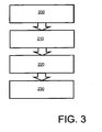
- Steps of the aforementioned method are shown in Figure 3 .
- the first step of installing the brake monitors 10 in association with the brake units 20 is denoted by 200.
- the second step of individually or group-wise actuating the brake units 20 in a sequence whilst monitoring corresponding brake unit 20 actuations by using the brake monitors 10 and generating corresponding brake unit actuation signals is denoted by 210.
- the third step of communicating the brake unit actuation signals from the brake monitors 10 to the at least one control apparatus 40 is denoted by 220.
- the fourth step of receiving the brake unit actuation signals at the at least one control apparatus 40, and identifying from the received brake unit actuation signals positions where the brake monitors 10 are installed on the vehicle 30 is denoted by 230.
- alternative communication routes are alternatively or additionally employed.
- Such alternative communication routes optionally include one or more of: optical communication, acoustic communication, hardwired connection.
- the at least one control apparatus 40 is beneficially implemented as an arrangements of one or more monitoring apparatus, for example implemented as a brake integrity monitoring system or apparatus.
Landscapes
- Engineering & Computer Science (AREA)
- Transportation (AREA)
- Mechanical Engineering (AREA)
- Valves And Accessory Devices For Braking Systems (AREA)
- Braking Arrangements (AREA)
Abstract
Claims (6)
- Procédé d'identification de positions de dispositifs de surveillance de frein (10) par rapport à des unités de freinage de roue (20) d'un véhicule, les dispositifs de surveillance de frein (10) pouvant être activés pour communiquer sans fil avec au moins un appareil de commandes (40) du véhicule (30),
caractérisé en ce que le procédé comprend les étapes consistant à :(a) installer les dispositifs de surveillance de frein (10) en association avec les unités de freinage (20) ;(b) actionner de manière individuelle ou par groupe les unités de freinage (20) dans une séquence tout en surveillant les actionnements de l'unité de freinage correspondante en utilisant les dispositifs de surveillance de frein (10) et en produisant des signaux d'actionnement de l'unité de freinage correspondante ;(c) communiquer les signaux d'actionnement d'unité de freinage provenant des dispositifs de surveillance de frein (10) au au moins un appareil de commande (40) ; et(d) recevoir les signaux d'actionnement d'unité de freinage au niveau du au moins un appareil de commande (40), et identifier à partir des signaux d'actionnement d'unité de freinage reçus les positions dans lesquelles les dispositifs de surveillance de frein (10) sont installés sur le véhicule (30). - Procédé selon la revendication 1, dans lequel le procédé comprend une étape consistant à munir chaque dispositif de surveillance de frein (10) d'au moins un code d'identification destiné à être utilisé lors d'une communication depuis le dispositif de surveillance de frein (10) vers le au moins un appareil de commande (40), le au moins un code d'identification validant le dispositif de surveillance de frein (10) pour être identifié uniquement individuellement ou à la manière d'un groupe par le au moins un appareil de commande (40) lors d'une communication avec celui-ci.
- Procédé selon les revendications 1 ou 2, dans lequel chaque dispositif de surveillance de frein (10) peut être actionné pour surveiller un mouvement d'au moins un bloc de frein (100) de son unité de freinage correspondante (20) pendant l'actionnement de l'unité de freinage (20).
- Procédé selon les revendications 1, 2 ou 3, dans lequel les dispositifs de surveillance de frein (10) peuvent être actionnés pour agir dans un premier état de veille pour conserver une puissance, et un second état actif pour communiquer une indication d'actionnement de leurs unités de freinage associées (20), dans lequel une commutation entre le premier état de veille et le second état actif survient pour chaque dispositif de surveillance de frein (10) en association avec un actionnement de son unité de freinage correspondante (20).
- Procédé selon l'une quelconque des revendications précédentes, dans lequel les dispositifs de surveillance de frein (10) sont reliés à des actionneurs (140) de leur unité de freinage correspondante (20) qui peut être actionnée pour appliquer le bloc de frein associé (100), les dispositifs de surveillance de frein étant montés dans des emplacements écartés des blocs de frein (100) pour réduire une exposition des dispositifs de surveillance de frein à une chaleur produite dans les blocs de frein lors d'un fonctionnement.
- Produit logiciel mémorisé sur un support de données, le produit logiciel pouvant être exécuté sur un matériel informatique pour mettre en oeuvre un procédé selon l'une quelconque des revendications 1 à 5.
Applications Claiming Priority (1)
| Application Number | Priority Date | Filing Date | Title |
|---|---|---|---|
| PCT/SE2008/000261 WO2009126068A1 (fr) | 2008-04-10 | 2008-04-10 | Procédé d’identification des positions des dispositifs de surveillance de freins |
Publications (3)
| Publication Number | Publication Date |
|---|---|
| EP2274534A1 EP2274534A1 (fr) | 2011-01-19 |
| EP2274534A4 EP2274534A4 (fr) | 2011-08-31 |
| EP2274534B1 true EP2274534B1 (fr) | 2012-08-15 |
Family
ID=41162072
Family Applications (1)
| Application Number | Title | Priority Date | Filing Date |
|---|---|---|---|
| EP08724174A Not-in-force EP2274534B1 (fr) | 2008-04-10 | 2008-04-10 | Procédé d identification des positions des dispositifs de surveillance de freins |
Country Status (5)
| Country | Link |
|---|---|
| US (1) | US20110029212A1 (fr) |
| EP (1) | EP2274534B1 (fr) |
| JP (1) | JP2011516339A (fr) |
| CN (1) | CN101999049A (fr) |
| WO (1) | WO2009126068A1 (fr) |
Families Citing this family (2)
| Publication number | Priority date | Publication date | Assignee | Title |
|---|---|---|---|---|
| US9416835B2 (en) * | 2014-11-13 | 2016-08-16 | GM Global Technology Operations LLC | Method of estimating brake pad wear and vehicle having a controller that implements the method |
| JP6879179B2 (ja) * | 2017-11-28 | 2021-06-02 | トヨタ自動車株式会社 | ブレーキシステム |
Family Cites Families (14)
| Publication number | Priority date | Publication date | Assignee | Title |
|---|---|---|---|---|
| DE4205911A1 (de) * | 1992-02-26 | 1993-09-02 | Uwatec Ag | Kontrollvorrichtung fuer den luftdruck von luftbereiften fahrzeugraedern |
| DE4214181C2 (de) * | 1992-04-30 | 1995-07-13 | Daimler Benz Ag | Verfahren zur Bremsbelagverschleißregelung im Sinne eines Ausgleichs von Bremsbelagverschleißunterschieden in einer druckmittelbetätigten Kraftfahrzeug-Bremsanlage |
| US5302939A (en) * | 1992-09-08 | 1994-04-12 | Schrader Automotive Inc. | Dual tire equalizer having remote indicator |
| DE19618658A1 (de) * | 1996-05-09 | 1997-11-13 | Continental Ag | Luftdruckkontrollsystem |
| KR100525577B1 (ko) * | 1996-10-11 | 2006-06-08 | 인디안헤드 인더스트리즈 인 코포레이티드 | 브레이크모니터링시스템 |
| DE10025502A1 (de) * | 2000-05-23 | 2001-11-29 | Bosch Gmbh Robert | Sensorsystem zur Erfassung von Meßgrößen an einem rotierenden Gegenstand |
| US20020116992A1 (en) * | 2001-02-26 | 2002-08-29 | Trw Inc. | System and method for monitoring wear of a vehicle component |
| US6696937B1 (en) * | 2001-05-14 | 2004-02-24 | Karl F. Kiefer | Wireless brake condition monitor |
| CN1206121C (zh) * | 2001-11-05 | 2005-06-15 | 黄添财 | 刹车衬片磨耗及胎压异常警示系统 |
| DE10207014A1 (de) * | 2002-02-19 | 2003-08-28 | Pex Kabeltechnik Gmbh | Fahrzeug |
| US6753771B2 (en) * | 2002-05-14 | 2004-06-22 | Indian Head Industries, Inc. | Vehicle monitoring system |
| US20040150516A1 (en) * | 2003-02-05 | 2004-08-05 | Delphi Technologies, Inc. | Wireless wheel speed sensor system |
| US20060042734A1 (en) * | 2004-08-24 | 2006-03-02 | Turner Douglas D | Wear component and warning system |
| SE530423C2 (sv) * | 2005-04-21 | 2008-06-03 | Volvo Lastvagnar Ab | System för identifiering av bromsbelägg |
-
2008
- 2008-04-10 JP JP2011503932A patent/JP2011516339A/ja not_active Ceased
- 2008-04-10 CN CN2008801285788A patent/CN101999049A/zh active Pending
- 2008-04-10 EP EP08724174A patent/EP2274534B1/fr not_active Not-in-force
- 2008-04-10 US US12/934,671 patent/US20110029212A1/en not_active Abandoned
- 2008-04-10 WO PCT/SE2008/000261 patent/WO2009126068A1/fr not_active Ceased
Also Published As
| Publication number | Publication date |
|---|---|
| CN101999049A (zh) | 2011-03-30 |
| WO2009126068A1 (fr) | 2009-10-15 |
| EP2274534A1 (fr) | 2011-01-19 |
| EP2274534A4 (fr) | 2011-08-31 |
| JP2011516339A (ja) | 2011-05-26 |
| US20110029212A1 (en) | 2011-02-03 |
Similar Documents
| Publication | Publication Date | Title |
|---|---|---|
| US8897957B2 (en) | Control and monitoring device of a vehicle having a tire-monitoring control unit and a brake control unit integrated in a subassembly | |
| RU2457131C2 (ru) | Система мониторинга железнодорожного поезда | |
| AU2018208682B2 (en) | Sensor system | |
| US10495168B2 (en) | Sensor-equipped vehicle braking systems, devices, and methods | |
| CN100429087C (zh) | 车辆车轮信息处理设备及其方法 | |
| JP4289561B2 (ja) | 車両の異常検出方法及びその装置並びにそのセンサユニット | |
| EP2817187B1 (fr) | Point d'accès de remorque | |
| US20160146279A1 (en) | Brake Pad Wear Monitoring System | |
| CN107667046A (zh) | 用于避免车辆的制动器的过热的方法和控制器 | |
| US20120006633A1 (en) | Vehicle Brake | |
| US8198993B2 (en) | System for monitoring the tire pressure in vehicles | |
| JP2008195384A (ja) | タイヤコントロールシステムおよび方法 | |
| JP2008260526A (ja) | タイヤ識別システム、それを応用したタイヤ空気圧モニタリングシステム及びタイヤ識別方法 | |
| CN101071304A (zh) | 用于车辆的电子控制系统及其控制方法 | |
| US20170307036A1 (en) | Brake telemetry systems and methods | |
| CN102371858A (zh) | 用于在双后轮胎车辆中识别轮胎位置的方法和系统 | |
| CN201105725Y (zh) | 一种汽车轮胎气压监测系统 | |
| CN112533807B (zh) | 电子制动系统 | |
| US20110029212A1 (en) | Method of identifying positions of brake monitors | |
| JP2007320423A (ja) | タイヤ位置検出システム | |
| CN109968923B (zh) | 轮胎压力监视单元 | |
| CN103648871A (zh) | 用于车辆的电子制动控制装置以及诊断仪器、接收站和电脑程序 | |
| CN103909794A (zh) | 一种轮胎压力传感器自动定位方法及对应的监测系统 | |
| US7565232B2 (en) | Control electronics integrated in a brake, preferably a disc brake | |
| CN203344666U (zh) | 多路汽车车轮温度实时监测装置 |
Legal Events
| Date | Code | Title | Description |
|---|---|---|---|
| PUAI | Public reference made under article 153(3) epc to a published international application that has entered the european phase |
Free format text: ORIGINAL CODE: 0009012 |
|
| 17P | Request for examination filed |
Effective date: 20101110 |
|
| AK | Designated contracting states |
Kind code of ref document: A1 Designated state(s): AT BE BG CH CY CZ DE DK EE ES FI FR GB GR HR HU IE IS IT LI LT LU LV MC MT NL NO PL PT RO SE SI SK TR |
|
| AX | Request for extension of the european patent |
Extension state: AL BA MK RS |
|
| DAX | Request for extension of the european patent (deleted) | ||
| A4 | Supplementary search report drawn up and despatched |
Effective date: 20110803 |
|
| RIC1 | Information provided on ipc code assigned before grant |
Ipc: F16D 66/00 20060101ALI20110728BHEP Ipc: B60T 17/22 20060101ALI20110728BHEP Ipc: F16D 66/02 20060101AFI20110728BHEP |
|
| GRAP | Despatch of communication of intention to grant a patent |
Free format text: ORIGINAL CODE: EPIDOSNIGR1 |
|
| GRAS | Grant fee paid |
Free format text: ORIGINAL CODE: EPIDOSNIGR3 |
|
| GRAA | (expected) grant |
Free format text: ORIGINAL CODE: 0009210 |
|
| AK | Designated contracting states |
Kind code of ref document: B1 Designated state(s): AT BE BG CH CY CZ DE DK EE ES FI FR GB GR HR HU IE IS IT LI LT LU LV MC MT NL NO PL PT RO SE SI SK TR |
|
| REG | Reference to a national code |
Ref country code: GB Ref legal event code: FG4D Ref country code: CH Ref legal event code: EP Ref country code: AT Ref legal event code: REF Ref document number: 571011 Country of ref document: AT Kind code of ref document: T Effective date: 20120815 |
|
| REG | Reference to a national code |
Ref country code: IE Ref legal event code: FG4D |
|
| REG | Reference to a national code |
Ref country code: DE Ref legal event code: R096 Ref document number: 602008018018 Country of ref document: DE Effective date: 20121011 |
|
| REG | Reference to a national code |
Ref country code: NL Ref legal event code: VDEP Effective date: 20120815 |
|
| REG | Reference to a national code |
Ref country code: AT Ref legal event code: MK05 Ref document number: 571011 Country of ref document: AT Kind code of ref document: T Effective date: 20120815 |
|
| PG25 | Lapsed in a contracting state [announced via postgrant information from national office to epo] |
Ref country code: NO Free format text: LAPSE BECAUSE OF FAILURE TO SUBMIT A TRANSLATION OF THE DESCRIPTION OR TO PAY THE FEE WITHIN THE PRESCRIBED TIME-LIMIT Effective date: 20121115 Ref country code: HR Free format text: LAPSE BECAUSE OF FAILURE TO SUBMIT A TRANSLATION OF THE DESCRIPTION OR TO PAY THE FEE WITHIN THE PRESCRIBED TIME-LIMIT Effective date: 20120815 Ref country code: FI Free format text: LAPSE BECAUSE OF FAILURE TO SUBMIT A TRANSLATION OF THE DESCRIPTION OR TO PAY THE FEE WITHIN THE PRESCRIBED TIME-LIMIT Effective date: 20120815 Ref country code: LT Free format text: LAPSE BECAUSE OF FAILURE TO SUBMIT A TRANSLATION OF THE DESCRIPTION OR TO PAY THE FEE WITHIN THE PRESCRIBED TIME-LIMIT Effective date: 20120815 Ref country code: IS Free format text: LAPSE BECAUSE OF FAILURE TO SUBMIT A TRANSLATION OF THE DESCRIPTION OR TO PAY THE FEE WITHIN THE PRESCRIBED TIME-LIMIT Effective date: 20121215 Ref country code: AT Free format text: LAPSE BECAUSE OF FAILURE TO SUBMIT A TRANSLATION OF THE DESCRIPTION OR TO PAY THE FEE WITHIN THE PRESCRIBED TIME-LIMIT Effective date: 20120815 |
|
| PG25 | Lapsed in a contracting state [announced via postgrant information from national office to epo] |
Ref country code: PT Free format text: LAPSE BECAUSE OF FAILURE TO SUBMIT A TRANSLATION OF THE DESCRIPTION OR TO PAY THE FEE WITHIN THE PRESCRIBED TIME-LIMIT Effective date: 20121217 Ref country code: LV Free format text: LAPSE BECAUSE OF FAILURE TO SUBMIT A TRANSLATION OF THE DESCRIPTION OR TO PAY THE FEE WITHIN THE PRESCRIBED TIME-LIMIT Effective date: 20120815 Ref country code: PL Free format text: LAPSE BECAUSE OF FAILURE TO SUBMIT A TRANSLATION OF THE DESCRIPTION OR TO PAY THE FEE WITHIN THE PRESCRIBED TIME-LIMIT Effective date: 20120815 Ref country code: BE Free format text: LAPSE BECAUSE OF FAILURE TO SUBMIT A TRANSLATION OF THE DESCRIPTION OR TO PAY THE FEE WITHIN THE PRESCRIBED TIME-LIMIT Effective date: 20120815 Ref country code: SI Free format text: LAPSE BECAUSE OF FAILURE TO SUBMIT A TRANSLATION OF THE DESCRIPTION OR TO PAY THE FEE WITHIN THE PRESCRIBED TIME-LIMIT Effective date: 20120815 Ref country code: SE Free format text: LAPSE BECAUSE OF FAILURE TO SUBMIT A TRANSLATION OF THE DESCRIPTION OR TO PAY THE FEE WITHIN THE PRESCRIBED TIME-LIMIT Effective date: 20120815 Ref country code: GR Free format text: LAPSE BECAUSE OF FAILURE TO SUBMIT A TRANSLATION OF THE DESCRIPTION OR TO PAY THE FEE WITHIN THE PRESCRIBED TIME-LIMIT Effective date: 20121116 |
|
| PG25 | Lapsed in a contracting state [announced via postgrant information from national office to epo] |
Ref country code: NL Free format text: LAPSE BECAUSE OF FAILURE TO SUBMIT A TRANSLATION OF THE DESCRIPTION OR TO PAY THE FEE WITHIN THE PRESCRIBED TIME-LIMIT Effective date: 20120815 |
|
| PG25 | Lapsed in a contracting state [announced via postgrant information from national office to epo] |
Ref country code: CZ Free format text: LAPSE BECAUSE OF FAILURE TO SUBMIT A TRANSLATION OF THE DESCRIPTION OR TO PAY THE FEE WITHIN THE PRESCRIBED TIME-LIMIT Effective date: 20120815 Ref country code: DK Free format text: LAPSE BECAUSE OF FAILURE TO SUBMIT A TRANSLATION OF THE DESCRIPTION OR TO PAY THE FEE WITHIN THE PRESCRIBED TIME-LIMIT Effective date: 20120815 Ref country code: EE Free format text: LAPSE BECAUSE OF FAILURE TO SUBMIT A TRANSLATION OF THE DESCRIPTION OR TO PAY THE FEE WITHIN THE PRESCRIBED TIME-LIMIT Effective date: 20120815 Ref country code: RO Free format text: LAPSE BECAUSE OF FAILURE TO SUBMIT A TRANSLATION OF THE DESCRIPTION OR TO PAY THE FEE WITHIN THE PRESCRIBED TIME-LIMIT Effective date: 20120815 Ref country code: ES Free format text: LAPSE BECAUSE OF FAILURE TO SUBMIT A TRANSLATION OF THE DESCRIPTION OR TO PAY THE FEE WITHIN THE PRESCRIBED TIME-LIMIT Effective date: 20121126 |
|
| PG25 | Lapsed in a contracting state [announced via postgrant information from national office to epo] |
Ref country code: SK Free format text: LAPSE BECAUSE OF FAILURE TO SUBMIT A TRANSLATION OF THE DESCRIPTION OR TO PAY THE FEE WITHIN THE PRESCRIBED TIME-LIMIT Effective date: 20120815 |
|
| PLBE | No opposition filed within time limit |
Free format text: ORIGINAL CODE: 0009261 |
|
| STAA | Information on the status of an ep patent application or granted ep patent |
Free format text: STATUS: NO OPPOSITION FILED WITHIN TIME LIMIT |
|
| 26N | No opposition filed |
Effective date: 20130516 |
|
| PG25 | Lapsed in a contracting state [announced via postgrant information from national office to epo] |
Ref country code: BG Free format text: LAPSE BECAUSE OF FAILURE TO SUBMIT A TRANSLATION OF THE DESCRIPTION OR TO PAY THE FEE WITHIN THE PRESCRIBED TIME-LIMIT Effective date: 20121115 |
|
| REG | Reference to a national code |
Ref country code: DE Ref legal event code: R097 Ref document number: 602008018018 Country of ref document: DE Effective date: 20130516 |
|
| PG25 | Lapsed in a contracting state [announced via postgrant information from national office to epo] |
Ref country code: CY Free format text: LAPSE BECAUSE OF FAILURE TO SUBMIT A TRANSLATION OF THE DESCRIPTION OR TO PAY THE FEE WITHIN THE PRESCRIBED TIME-LIMIT Effective date: 20120815 Ref country code: MC Free format text: LAPSE BECAUSE OF FAILURE TO SUBMIT A TRANSLATION OF THE DESCRIPTION OR TO PAY THE FEE WITHIN THE PRESCRIBED TIME-LIMIT Effective date: 20120815 |
|
| REG | Reference to a national code |
Ref country code: CH Ref legal event code: PL |
|
| GBPC | Gb: european patent ceased through non-payment of renewal fee |
Effective date: 20130410 |
|
| REG | Reference to a national code |
Ref country code: IE Ref legal event code: MM4A |
|
| PG25 | Lapsed in a contracting state [announced via postgrant information from national office to epo] |
Ref country code: LI Free format text: LAPSE BECAUSE OF NON-PAYMENT OF DUE FEES Effective date: 20130430 Ref country code: DE Free format text: LAPSE BECAUSE OF NON-PAYMENT OF DUE FEES Effective date: 20131101 Ref country code: GB Free format text: LAPSE BECAUSE OF NON-PAYMENT OF DUE FEES Effective date: 20130410 Ref country code: CH Free format text: LAPSE BECAUSE OF NON-PAYMENT OF DUE FEES Effective date: 20130430 |
|
| REG | Reference to a national code |
Ref country code: FR Ref legal event code: ST Effective date: 20131231 |
|
| REG | Reference to a national code |
Ref country code: DE Ref legal event code: R119 Ref document number: 602008018018 Country of ref document: DE Effective date: 20131101 |
|
| PG25 | Lapsed in a contracting state [announced via postgrant information from national office to epo] |
Ref country code: FR Free format text: LAPSE BECAUSE OF NON-PAYMENT OF DUE FEES Effective date: 20130430 Ref country code: IT Free format text: LAPSE BECAUSE OF NON-PAYMENT OF DUE FEES Effective date: 20130410 |
|
| PG25 | Lapsed in a contracting state [announced via postgrant information from national office to epo] |
Ref country code: IE Free format text: LAPSE BECAUSE OF NON-PAYMENT OF DUE FEES Effective date: 20130410 |
|
| PG25 | Lapsed in a contracting state [announced via postgrant information from national office to epo] |
Ref country code: MT Free format text: LAPSE BECAUSE OF FAILURE TO SUBMIT A TRANSLATION OF THE DESCRIPTION OR TO PAY THE FEE WITHIN THE PRESCRIBED TIME-LIMIT Effective date: 20120815 |
|
| PG25 | Lapsed in a contracting state [announced via postgrant information from national office to epo] |
Ref country code: TR Free format text: LAPSE BECAUSE OF FAILURE TO SUBMIT A TRANSLATION OF THE DESCRIPTION OR TO PAY THE FEE WITHIN THE PRESCRIBED TIME-LIMIT Effective date: 20120815 |
|
| PG25 | Lapsed in a contracting state [announced via postgrant information from national office to epo] |
Ref country code: HU Free format text: LAPSE BECAUSE OF FAILURE TO SUBMIT A TRANSLATION OF THE DESCRIPTION OR TO PAY THE FEE WITHIN THE PRESCRIBED TIME-LIMIT; INVALID AB INITIO Effective date: 20080410 Ref country code: LU Free format text: LAPSE BECAUSE OF NON-PAYMENT OF DUE FEES Effective date: 20130410 |