EP2274660B1 - Kraftrückkoppelungsschnittstelle mit verbesserten wahrnehmungen - Google Patents
Kraftrückkoppelungsschnittstelle mit verbesserten wahrnehmungen Download PDFInfo
- Publication number
- EP2274660B1 EP2274660B1 EP09738100.8A EP09738100A EP2274660B1 EP 2274660 B1 EP2274660 B1 EP 2274660B1 EP 09738100 A EP09738100 A EP 09738100A EP 2274660 B1 EP2274660 B1 EP 2274660B1
- Authority
- EP
- European Patent Office
- Prior art keywords
- magnetic field
- generating
- fluid
- interface according
- shaft
- Prior art date
- Legal status (The legal status is an assumption and is not a legal conclusion. Google has not performed a legal analysis and makes no representation as to the accuracy of the status listed.)
- Active
Links
Images



Classifications
-
- G—PHYSICS
- G05—CONTROLLING; REGULATING
- G05G—CONTROL DEVICES OR SYSTEMS INSOFAR AS CHARACTERISED BY MECHANICAL FEATURES ONLY
- G05G1/00—Controlling members, e.g. knobs or handles; Assemblies or arrangements thereof; Indicating position of controlling members
- G05G1/08—Controlling members for hand actuation by rotary movement, e.g. hand wheels
-
- B—PERFORMING OPERATIONS; TRANSPORTING
- B60—VEHICLES IN GENERAL
- B60K—ARRANGEMENT OR MOUNTING OF PROPULSION UNITS OR OF TRANSMISSIONS IN VEHICLES; ARRANGEMENT OR MOUNTING OF PLURAL DIVERSE PRIME-MOVERS IN VEHICLES; AUXILIARY DRIVES FOR VEHICLES; INSTRUMENTATION OR DASHBOARDS FOR VEHICLES; ARRANGEMENTS IN CONNECTION WITH COOLING, AIR INTAKE, GAS EXHAUST OR FUEL SUPPLY OF PROPULSION UNITS IN VEHICLES
- B60K35/00—Instruments specially adapted for vehicles; Arrangement of instruments in or on vehicles
- B60K35/10—Input arrangements, i.e. from user to vehicle, associated with vehicle functions or specially adapted therefor
-
- B—PERFORMING OPERATIONS; TRANSPORTING
- B60—VEHICLES IN GENERAL
- B60K—ARRANGEMENT OR MOUNTING OF PROPULSION UNITS OR OF TRANSMISSIONS IN VEHICLES; ARRANGEMENT OR MOUNTING OF PLURAL DIVERSE PRIME-MOVERS IN VEHICLES; AUXILIARY DRIVES FOR VEHICLES; INSTRUMENTATION OR DASHBOARDS FOR VEHICLES; ARRANGEMENTS IN CONNECTION WITH COOLING, AIR INTAKE, GAS EXHAUST OR FUEL SUPPLY OF PROPULSION UNITS IN VEHICLES
- B60K35/00—Instruments specially adapted for vehicles; Arrangement of instruments in or on vehicles
- B60K35/20—Output arrangements, i.e. from vehicle to user, associated with vehicle functions or specially adapted therefor
- B60K35/25—Output arrangements, i.e. from vehicle to user, associated with vehicle functions or specially adapted therefor using haptic output
-
- F—MECHANICAL ENGINEERING; LIGHTING; HEATING; WEAPONS; BLASTING
- F16—ENGINEERING ELEMENTS AND UNITS; GENERAL MEASURES FOR PRODUCING AND MAINTAINING EFFECTIVE FUNCTIONING OF MACHINES OR INSTALLATIONS; THERMAL INSULATION IN GENERAL
- F16F—SPRINGS; SHOCK-ABSORBERS; MEANS FOR DAMPING VIBRATION
- F16F9/00—Springs, vibration-dampers, shock-absorbers, or similarly-constructed movement-dampers using a fluid or the equivalent as damping medium
- F16F9/32—Details
- F16F9/53—Means for adjusting damping characteristics by varying fluid viscosity, e.g. electromagnetically
- F16F9/535—Magnetorheological [MR] fluid dampers
-
- G—PHYSICS
- G05—CONTROLLING; REGULATING
- G05G—CONTROL DEVICES OR SYSTEMS INSOFAR AS CHARACTERISED BY MECHANICAL FEATURES ONLY
- G05G5/00—Means for preventing, limiting or returning the movements of parts of a control mechanism, e.g. locking controlling member
- G05G5/03—Means for enhancing the operator's awareness of arrival of the controlling member at a command or datum position; Providing feel, e.g. means for creating a counterforce
-
- B—PERFORMING OPERATIONS; TRANSPORTING
- B60—VEHICLES IN GENERAL
- B60K—ARRANGEMENT OR MOUNTING OF PROPULSION UNITS OR OF TRANSMISSIONS IN VEHICLES; ARRANGEMENT OR MOUNTING OF PLURAL DIVERSE PRIME-MOVERS IN VEHICLES; AUXILIARY DRIVES FOR VEHICLES; INSTRUMENTATION OR DASHBOARDS FOR VEHICLES; ARRANGEMENTS IN CONNECTION WITH COOLING, AIR INTAKE, GAS EXHAUST OR FUEL SUPPLY OF PROPULSION UNITS IN VEHICLES
- B60K2360/00—Indexing scheme associated with groups B60K35/00 or B60K37/00 relating to details of instruments or dashboards
- B60K2360/126—Rotatable input devices for instruments
Definitions
- the present invention relates to sensory interfaces offering a return of effort to the user, used in particular in the field of haptic devices and in the fields of virtual reality and the automobile.
- This type of haptic interface is for example used in motor vehicles, forming an onboard haptic interface assisting the automotive driver.
- This interface takes the form of a rotary button with force feedback, and allows the user to interact with various equipment or accessories of the vehicle such as GPS (Global Positioning System in English terminology or Global positioning system), the radio, air conditioning ...
- Such a button is currently used in high-end motor vehicles.
- This button has no sensory feedback in effort. Indeed, the resistance felt by the user to switch from one notch to another is invariable, the latter being predefined during the design of the button. Thus, the return force has a constant intensity regardless of the speed of manipulation of the button or the type of control desired.
- the resistance applied by the button is obtained by means of a DC motor associated with gearboxes.
- this type of generator resistance does not allow to offer a high sensitivity in the effort felt by the user.
- it is bulky and of a significant mass. This limits its application in embedded systems.
- haptic interfaces in which the force feedback is obtained by using a magnetorheological fluid. By applying a magnetic field to this fluid, the apparent viscosity thereof increases and allows to exert a braking force to an integral element of the button and bathed in this fluid.
- Such interfaces are described in the document US 2002/0057152 .
- the known interfaces do not allow, in the known structure, to achieve an interesting compromise between their size, the resistive torque provided by the button, and the power consumption for generate the magnetic field in the magneto-rheological fluid.
- a haptic interface in which the resistance to the movement of a button manipulated by a user is generated by means of a magnetorheological fluid, the change in the apparent viscosity thereof being achieved by means a magnetic circuit comprising one or more permanent magnets associated with a system for generating a variable magnetic field.
- a resistor is applied in the absence of power supply, unlike magneto-rheological fluid interfaces of the state of the art. Moreover, it is possible to cancel or strengthen the magnetic field of the permanent magnet by the system for generating a variable magnetic field, which makes it possible to have a wide range of resistant couples, adaptable to each type of magnet. operation of the interface, unlike current interfaces with electric motors, whose return efforts are frozen.
- the magnetic field generated by the magnet is sufficient so that the apparent viscosity of the fluid is such that the movement of the button is prevented, thus locking the interface in the absence of current.
- the interface is unlocked by applying a magnetic field by means of the system for generating a variable magnetic field. This avoids, unlike the existing interfaces, to continuously supply the magnetic field generation system to block the button, or to provide a complex mechanism for lock and unlock the button, making the use of the interface less user-friendly and intuitive.
- the usage range is doubled.
- the developed haptic interface thus allows a semi-active control of the button in effort to generate different sensations, and this through a magneto-rheological fluid while providing a footprint and reduced power consumption.
- the term "semi-active system” means a system that forms a compromise between an "active" system and a "passive” system. It can be controlled in real time but can not inject energy into the controlled system. It controls the haptic feedback felt by the user by reaction by absorbing / dissipating energy according to a predefined control law.
- the interaction element comprises a circular section cylindrical element and the magnetic field generating means generates a radial field with respect to this interaction element.
- the present invention therefore mainly relates to a haptic interface comprising an interaction element with a user, a rotation shaft of which is integral in rotation said interaction element with the user, an interaction element with a fluid, said interaction element with the fluid being rotatably connected to said shaft, said fluid being of the magnetorheological type, a system for generating a magnetic field in said fluid, and a control unit able to generate orders to said generating system magnetic field to modify the magnetic field, said system comprising means for generating a variable magnetic field and means for generating a permanent magnetic field.
- the haptic interface according to the invention may comprise at least one sensor for angular position, angular velocity and / or angular acceleration of said shaft, said control unit generating the commands according to the information provided by said at least one sensor. position, velocity and / or angular acceleration.
- control unit generates commands to the magnetic field generation system at fixed or variable time intervals.
- Said magnetic field generation system advantageously generates a radial magnetic field, which makes it possible to increase the damping forces.
- the means for generating a permanent magnetic field comprise, for example at least one permanent magnet; and the means for generating a variable magnetic field comprise for example at least one electromagnetic coil. These two elements are associated with a magnetic circuit made of ferromagnetic materials. The axis of the coil is advantageously coincident with that of the rotation shaft.
- the element for interaction with the fluid comprises at least one cylindrical wall of revolution of longitudinal axis and a bottom, said bottom being fixed to the rotation shaft, the fluid coming into contact on an inner face and a outer face of said side wall.
- the fluid interaction element comprises a plurality of concentric lateral walls spaced from each other and integral with the bottom, which increases the shear forces applied to the fluid.
- the means for generating a permanent magnetic field are arranged inside the element for interaction with the fluid, immobile with respect thereto and in which the means for generating a variable magnetic field are arranged inside the fluid interaction element, immobile with respect to this one.
- the coil can then surround the permanent magnet.
- the permanent magnet may be formed of at least one sleeve surrounding the coil
- the means for generating a permanent magnetic field are arranged between two concentric lateral walls of the interaction element and are immobile with respect thereto.
- the means for generating a permanent magnetic field are fixed on the interaction element with the fluid and the means for generating a variable magnetic field are immobile with respect thereto.
- the means for generating a variable magnetic field are arranged inside the interaction element and immobile with respect thereto.
- the means for generating a permanent magnetic field and the means for generating a variable magnetic field can also be fixed on the element for interaction with the fluid.
- the shaft passes through the magnetic field generation system.
- the position sensor may, for example be provided at a longitudinal end of the shaft and comprise a portion integral in rotation with the shaft and a stationary portion relative to the shaft.
- the integral part of the shaft can then be an optical wheel and the stationary part an optical fork.
- the interface according to the invention comprises a rod passing right through the shaft, said rod being able to move longitudinally and a device for detecting the displacement of said rod.
- the interface may also include a thermal device capable of modifying the temperature of the interaction element with the user, the thermal device comprising at least one Pelletier cell and / or a device able to vibrate the interaction element. with the user.
- the present invention also relates to a haptic assembly comprising a frame and the interface according to the present invention mounted on this frame, said interface being movable along the axis of the shaft.
- the interface may be mobile in translation in at least one direction orthogonal to the longitudinal axis, and / or is rotatable about at least one direction orthogonal to the longitudinal axis.
- the haptic assembly according to the invention may comprise force feedback devices for opposing a resistance during a movement along at least one axis orthogonal to the longitudinal axis or around it.
- the haptic interface has at least one degree of rotation about an axis X generally forming an axis of revolution for the interface.
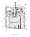
- FIG. 1A and 1B we can see a first embodiment of an interface according to the invention comprising an element 1 intended to be manipulated by a user and which will be designated later "button", this button is rotatably mounted on a shaft 2 X axis, and a force-generating device 4 resistant to the rotation of the shaft 2.
- the device 4 comprises a fluid whose characteristics can be modified by means of a magnetic field and a system for generating a magnetic field 6 received in a housing 8.
- the fluid is for example a magneto-rheological liquid 5.
- the casing 8 of cylindrical shape is formed by a side wall 8.1, a lower bottom 8.2 and an upper bottom 8.3.
- the shaft 2 passes through the upper bottom 8.3 and penetrates inside the housing 8.
- the housing 8 delimits a sealed chamber 10 confining the magnetorheological fluid 5, this chamber being subjected to a magnetic field generated by the system 6.
- the device 4 also comprises an element 12 integral in rotation with the shaft 2 and housed in the sealed chamber 10. This element is able to interact with the magnetorheological fluid 5, the rotation of the element 12 being more or less braked. by the magneto-rheological fluid 5 as a function of its apparent viscosity.
- the element 12 has the shape of a cylindrical bell of circular cross section formed of a side wall 12.1 and a bottom 12.2.
- the sealed chamber has a shape corresponding to that of the bell 12, which reduces the amount of fluid required.
- the element 12 interacting with the fluid has the shape of an inverted U.
- the bottom 12.2 is fixed on the end of the shaft 2 penetrating into the sealed chamber 10, as well as the chamber 10.
- the side wall 12.1 is made of material capable of driving a magnetic field, advantageously made of ferromagnetic material, thus the magnetic permeability of the side wall is reduced, improving the conduction of the magnetic field.
- the sealed chamber 10 is completely filled with magnetorheological fluid 5.
- the bell 12 is thus completely immersed in the magnetorheological fluid 5. More particularly, the inner and outer faces of the wall 12.1 are in contact with the magnetorheological fluid 5. But it could be expected that only the lateral wall 12.1 is immersed in the magneto-rheological fluid 5.
- the shaft 2 is supported by bearings 14.1, 14.2, sealingly insulated from the magnetorheological fluid 5.
- a sealing element 16, visible on the Figure 1B is provided between the sealed chamber 10 and the zone containing the bearings 14.1, 14.2.
- the sealing means surrounds the rotation shaft 2, which comprises an inner lip 16.1 bordering the rotation shaft 2 and providing a dynamic seal and an outer lip 16.2 in static contact with the housing. Sealing can be provided by any other type of joint, conventional or not, such as a ferrofluid held in place with a permanent magnet.
- the magnetic field generation system 6 is capable of generating a variable magnetic field so as to vary the viscosity of the magnetorheological fluid 5.
- the system 6 comprises a means 18 capable of generating a permanent magnetic field in the absence of an electrical supply, for example a permanent magnet, and means 20 capable of generating a variable magnetic field.
- the permanent magnetization means 18 will be designated by magnet permanent, but any other device offering such magnetization is not beyond the scope of the present invention.
- the magnet is, in the example shown, formed by a disk disposed inside the bell 12.
- the means for generating a variable magnetic field 20 is formed, for example by at least one coil disposed inside the bell 12 and surrounding the permanent magnet 20.
- the coil (s) has (have) a axis coincident with the longitudinal axis X.
- the system 6 comprises a magnetic circuit for guiding the magnetic field so that the field lines pass through the side wall 12.1 of the bell 12 and close inside the side wall 8.1, so that the fluid magneto-rheological 5 on either side of the side wall 12.1 is actually subject to the magnetic field.
- the permanent magnet 18 and the coil 20 are able to generate a magnetic field passing through the fluid and closing on the magnet and the coil.
- the magnetic circuit comprises a piece 22 of material capable of conducting the magnetic field forming a core, disposed inside the bell and in which the permanent magnet 18 and the coil 20 are arranged.
- the core 22 in the form of a regular cylinder has a lower portion 22.1 and an upper portion 22.2, the magnet and the coil being sandwiched between the two parts 22.1, 22.2.
- the chamber 10 is delimited, on the one hand by the outer faces of the core 22, by the outer lateral wall 8.1 and by an upper partition wall 25 through which the rotation shaft 2 passes.
- the parts 22.1, 22.2 each comprise a shoulder 23.1, 23.2 defined between a portion of larger diameter and a smaller diameter portion
- the magnet 18 is disposed between the free ends of the parts of smaller diameter
- the coil 20 is mounted around the smaller diameter portions resting on the shoulders 23.1, 23.2 by its two axial ends.
- the magnetic circuit also comprises the outer wall 8.1 of the housing 8, forming the outer wall of the sealed chamber 10.
- the magnetic circuit is received in an envelope 9, forming the outer envelope of the haptic device.
- the magnetic circuit is also formed by the side wall 12.1 of the bell 12 made of a material capable of driving a magnetic field.
- the field lines of the LCA magnet pass through the upper part 22.1 of the core, then the chamber 10 via the side wall 12.1 of the bell 12, the outer side wall 8.1 of the housing 8, the lower part 22.2 of the core 22 and close on the magnet 18.
- the LCB field lines of the coil 20 take the same magnetic circuit as the magnetic field lines LCA of the permanent magnet 18.
- This architecture according to the present invention allows a very good guidance of the magnetic field generated by the magnet 18 and the coil 20.
- the central core 22 and the wall 8.1 form a stator, while the bell 12 for rotation about the X axis forms a rotor.
- the upper part of the housing receiving the bearings 14.1, 14.2, the shaft, the bottom of the bell 12.2 are made of non-magnetic material, and the bottom bottom 8.2 of the housing to prevent the dispersion of the field lines.
- Means 28 are also provided for measuring the angular position of the bell 12 and thus of the button 1. These means are, for example, arranged between the two bearings 14.1, 14.2 and are formed by an optical encoder-type rotation sensor formed by an encoder wheel 28.1 integral in rotation with the shaft 2 and an optical fork 28.2 fixed to the housing.
- Any sensor capable of providing a logical or analog image of the position of the bell 12 is within the scope of the present invention.
- the sensor 28 is connected to a control unit (not shown) to which it transmits its measurements.
- the coil 20 is, in turn, connected to a source of electric current (not shown) controlled by the control unit to vary the intensity and direction of the current in the coil depending on the position of the bell 12, and therefore the button 1, measured by the sensor 28.
- a source of electric current not shown
- the rotation sensor 28 detects the rotation of the shaft 2 and transmits this information, as well as the measurement of the angular displacement, the angular velocity and / or the angular acceleration of the shaft 2 and, therefore of the bell 12, to the control unit.
- the control unit based on the received information generates an order to the power supply to send a current of a given intensity in a given direction according to prerecorded models or according to a communication with an external system (such as for example the GPS system in an automobile), to the coil 20.
- an external system such as for example the GPS system in an automobile
- This current may be zero if the control unit estimated that the magnetic field generated by the permanent magnet 18 is sufficient to modify the viscosity apparent fluid 5 to generate sufficient resistant forces on the bell 12.
- This current can be such that it increases the magnetic field, therefore the apparent viscosity of the fluid and, consequently, the resistant forces on the bell 12.
- This current may be such that the coil 20 generates a magnetic field in the opposite direction to that of the magnetic field produced by the permanent magnet 18, the addition of the two fields then gives a magnetic field resulting from reduced intensity, or even zero compared to that of the field produced by the permanent magnet 18 alone.
- the characteristics of the current sent into the coil may also be a function of the speed with which the knob 1 is rotated.
- the sensor may be a displacement sensor, a speed or acceleration sensor.
- the information on the movement is processed by the controller in order to define the setpoint to be sent to the power unit.
- the present invention it is possible to generate a resistive force in the absence of current.
- the permanent magnet more particularly the magnetic field that it generates, so that it modifies the apparent viscosity of the fluid so that the resistant forces on the bell immobilize the knob in rotation, it is then possible to lock the interface without consuming electricity.
- the bell 12 comprises magnets 18.1 'on the inner face and magnets 18.2' on the outer face of its side wall 12.1. These are for example tubular.
- the bell has an annular projection 30 substantially halfway up the bell, the tubular magnets 18.1 'and 18.2' being arranged above and below this projection.
- FIG. 3 another embodiment of the interface according to the invention can be seen in which the bell is doubled in order to increase the interaction surface with the fluid.
- the bell 12 has an outer lateral wall 12.1 'and an inner side wall 12.1 "concentric cylindrical integral with the bottom 12.2, and spaced apart from each other to allow the fluid to penetrate between the two walls.
- the fluid is on either side of the two concentric walls, the shear surface of the fluid is approximately doubled compared to that of the interface of the Figures 1A and 1B .
- this interface differs from that described so far in that the rotation shaft passes through the stator, more particularly the system for generating the magnetic field.
- the interface comprises a shaft 102 of longitudinal axis X to which is fixed at a first end 102.1 the button to be manipulated by the user.
- the shaft 102 is rotatably mounted in a housing 108 by means of bearings 114.1 and 114.2.
- the housing 108 forms a stator and the shaft 102 forms a rotor of which is integral in rotation a bell 112 bathed in a fluid whose viscosity properties may vary with the magnetic field.
- the position, speed or acceleration sensor 128 is, in this representation, placed at a lower end of the shaft 102.2 opposite to that to which the button (not shown) is attached. This is of the same type as previously described, it comprises, for example, a coding wheel 128.1 and an optical fork 128.2. The sensor is isolated from the fluid at the bearing 114.2.
- the magnetic circuit is similar to that of the example of Figures 1A and 1B it comprises a permanent magnet 118 in the form of a disk in the center of the core and a coil 120.
- the side wall 108.1 of the housing is made of magnetic material and the core 122.
- the permanent magnet 118 is no longer disposed in the core within the bell 112, but in the side wall 108.1 of the housing.
- the magnet has in this configuration the shape of a ring provided radially in alignment with the coil 120 and coaxial with it.
- the side wall 108.1 is made of a material capable of driving a magnetic field.
- the central core 122 is in one piece of magnetic material and has an annular groove in which the coil 120 is mounted. The coil 120 then projects radially from the radially outer periphery of the core.
- the magnet 118 is formed of two cylindrical sleeves 118.1, 118.2 arranged for one above the coil and, for the other, below the coil.
- the side wall 108.1 is made of a material capable of driving a magnetic field.
- Interfaces according to the second exemplary embodiment comprising a bell with several concentric skirts similar to that shown in FIG. figure 3 are within the scope of the present invention.
- the button is movable along the axis X.
- the shaft 102 is hollow and a rod 103 is movably mounted along the axis X inside the shaft 102.
- the rod 103 is secured to the button by a first axial end 103.1. The rod passes right through the shaft 102.
- the rod 102 and the shaft are integral in rotation, thus a rotation of the button is transmitted to the shaft via the rod 103.
- An axial displacement sensor 134 is provided to detect the axial displacement of the rod 103.
- This sensor may for example be an electric switch 134 arranged on the lower bottom 108.2 of the housing opposite the second longitudinal end 103.21 of the rod 103.
- This electric switch is connected to the control unit and can, by example serve as a validation system.
- the user can thus with one hand select a tab in a menu by moving a cursor by rotation of the button around the axis X and validate this choice by pressing the button causing the axial displacement of the rod 102 and switching the contactor 134.
- the axial displacement sensor 134 may be of any other type, for example optical or magnetic.
- the second embodiment is particularly suitable for the longitudinal displacement of the button, since the capture of its displacement is easy by using the bottom of the interface which is unused.
- a third exemplary embodiment of an interface according to the present invention can be seen, differing from the first and second exemplary embodiments in that the interface no longer includes a bell interacting in the fluid, but it is directly the central core integral in rotation with the rotation shaft which interacts with the fluid to undergo braking.
- the references are increased by 200 compared to those used for the first embodiment.
- the core 222 and the shaft 202 are integral in rotation, the core then being rotated in the fluid.
- the core 222 has an upper half portion 236 provided with an axial projection 202.1 forming the portion of the shaft 202 attached to the knob and a lower half portion 238 provided with an axial projection 202.2 of which is secured to the position sensor 228. These two half parts are integral with each other, glued or fixed by any other means.
- the permanent magnet 218 in the form of a disk is interposed between the upper half-portion 236 and the lower half-portion 238.
- the coil is embedded in the pivoting central core with the magnet 218.
- the interface according to the present invention can be seen integrated into a device 40 provided with a frame 42 on which it is mounted able to translate along Y and Z. axes, thus forming a "joystick" type command.
- the device may comprise force feedback systems in these directions Y and Z.
- the interface is mounted pivotable about the Y and Z axes according to the arrows 44, 46 respectively.
- a thermal device to simulate temperature variations, this device being for example a Peltier cell.
- this device being for example a Peltier cell.
- the user controlling a lowering of temperature would feel an impression of coldness at the level of the fingers handling the button, and in the case where it commands an elevation of the temperature, would feel an impression of warm at the level of his fingers manipulating the button.
- the information thus transmitted to the user would be more intuitive, the user could operate the button only according to how he feels. The driver can no longer perform a visual check of the screen, driving safety and comfort are therefore improved.
- force or torque sensors to measure the force or torque applied to the button, and adapt the resistance to the value of this effort or torque. For example, in the case where a large torque is applied to the button, the resistance to rotation generated by the fluid can be increased by generating a larger magnetic field.
- control unit can receive other information than the angular position of the rotation shaft, the angular acceleration or the angular speed of the button for controlling the magnetic field to be applied to the fluid, for example information relating to the pressure exerted on it, information concerning the state of the vehicle (for example, the speed, the GPS position, the indoor and outdoor temperature, etc.).
- the applied return can also be independent of external information by taking for example a time base.
- the haptic feedback does not depend on the movement made but on the time. For example, we can apply haptic jerks to a fixed frequency, whatever the speed of rotation.
Landscapes
- Engineering & Computer Science (AREA)
- Physics & Mathematics (AREA)
- Mechanical Engineering (AREA)
- Automation & Control Theory (AREA)
- General Engineering & Computer Science (AREA)
- General Physics & Mathematics (AREA)
- Chemical & Material Sciences (AREA)
- Combustion & Propulsion (AREA)
- Transportation (AREA)
- Electromagnetism (AREA)
- Mechanical Control Devices (AREA)
- User Interface Of Digital Computer (AREA)
- Position Input By Displaying (AREA)
Claims (20)
- Haptische Schnittstelle, enthaltend ein Element zur Interaktion mit einem Nutzer, eine Drehwelle (2, 102, 202) mit Längsachse (X), mit der das Element zur Interaktion mit dem Nutzer (1) drehfest verbunden ist, ein Element zur Interaktion mit einem Fluid (12, 112, 212), wobei das Element zur Interaktion mit einem Fluid (12, 112, 212) drehfest mit der Welle (2, 102, 202) verbunden ist, wobei das Fluid magneto-rheologischer Art ist, ein System (6) zum Erzeugen eines Magnetfeldes in dem Fluid, das dazu bestimmt ist, die Viskosität desselben zu verändern, und eine Steuereinheit, die dazu geeignet ist, dem System (6) zum Erzeugen des Magnetfeldes Befehle zu erteilen, um das Magnetfeld zu verändern, wobei das Element (12, 112, 212) zur Interaktion mit dem Fluid, das Fluid und das System zum Erzeugen eines Magnetfeldes in einem Gehäuse (8) aufgenommen sind, dadurch gekennzeichnet, dass das System zum Erzeugen eines Magnetfeldes Mittel zum Erzeugen eines veränderlichen Magnetfeldes (20, 120, 220, 32) und Mittel zum Erzeugen eines permanenten Magnetfeldes (18, 18", 118, 218) aufweist, wobei die Mittel zum Erzeugen eines permanenten Magnetfeldes (18, 18", 118, 218) in dem Gehäuse (8) so angeordnet sind, dass sie eine Erhöhung der Viskosität des Fluids und eine permanente Widerstandskraft gegen das Element zur Interaktion mit dem Fluid bewirken.
- Haptische Schnittstelle nach Anspruch 1, wobei die Mittel zum Erzeugen eines permanenten Magnetfeldes (18, 18", 118, 218) innerhalb des Gehäuses und/oder in einer Seitenwand des Gehäuses (8) angeordnet sind.
- Haptische Schnittstelle nach einem der Ansprüche 1 oder 2, enthaltend zumindest einen Winkelpositions-, Winkelgeschwindigkeits- und/oder Winkelbeschleunigungssensor (28, 128, 228) für die Welle (2, 102, 202), wobei die Steuereinheit Befehle in Abhängigkeit von den Informationen erzeugt, die von dem zumindest einen Winkelpositions-, Winkelgeschwindigkeits- und/oder Winkelbeschleunigungssensor (28, 128, 228) bereitgestellt werden.
- Haptische Schnittstelle nach einem der Ansprüche 1 bis 3, wobei die Steuereinheit dem System zum Erzeugen eines Magnetfeldes Befehle in festen oder variablen vorgegebenen Zeitintervallen erteilt.
- Haptische Schnittstelle nach einem der Ansprüche 1 bis 4, wobei das System zum Erzeugen (6) eines Magnetfeldes ein radiales Magnetfeld erzeugt.
- Haptische Schnittstelle nach einem der Ansprüche 1 bis 5, wobei die Mittel zum Erzeugen eines permanenten Magnetfeldes (18, 18", 118, 218), zumindest einen Permanentmagneten aufweisen.
- Haptische Schnittstelle nach einem der Ansprüche 1 bis 6, wobei die Mittel zum Erzeugen eines variablen Magnetfeldes (20, 120, 220) zumindest eine elektromagnetische Spule aufweisen.
- Haptische Schnittstelle nach einem der Ansprüche 1 bis 7, wobei das Element zur Interaktion mit dem Fluid (12, 112) zumindest eine zylindrische Umlaufwand (12.1, 112.1) mit einer Längsachse (X) und einen Boden aus nichtmagnetischem Material (12.2) aufweist, wobei der Boden (12.2) an die Drehwelle (2, 102, 202) befestigt ist, wobei das Fluid an einer Innenseite und an einer Außenseite der Seitenwand (12.1, 112.2) in Kontakt gelangt.
- Haptische Schnittstelle nach Anspruch 8, wobei das Element (12) zur Interaktion mit dem Fluid mehrere konzentrische Seitenwände (12.1', 12.1") aufweist, die voneinander beabstandet und fest mit dem Boden aus nichtmagnetischem Material (12.2) verbunden sind.
- Haptische Schnittstelle nach einem der Ansprüche 1 bis 9, wobei die Mittel zum Erzeugen eines permanenten Magnetfeldes innerhalb des Elements (12) zur Interaktion mit dem Fluid angeordnet sind, gegenüber dem Gehäuse unbeweglich sind und wobei die Mittel zum Erzeugen eines variablen Magnetfeldes (20) innerhalb des Elements (12) zur Interaktion mit dem Fluid angeordnet und gegenüber dem Gehäuse unbeweglich sind.
- Haptische Schnittstelle nach Anspruch 9, wobei die Mittel zum Erzeugen eines permanenten Magnetfeldes (18") zwischen zwei konzentrischen Seitenwänden (12.1', 12.1") der Glocke (12) angeordnet und gegenüber dem Gehäuse unbeweglich sind.
- Haptische Schnittstelle nach einem der Ansprüche 1 bis 9, wobei die Mittel zum Erzeugen eines permanenten Magnetfeldes an das Element zur Interaktion mit dem Fluid (12, 112, 212) befestigt sind und die Mittel zum Erzeugen eines variablen Magnetfeldes (20, 120, 220) gegenüber dem Gehäuse unbeweglich sind.
- Haptische Schnittstelle nach Anspruch 12, wobei die Mittel zum Erzeugen eines variablen Magnetfeldes (20, 32) innerhalb des Interaktionselements angeordnet sind, das gegenüber dem Gehäuse unbeweglich ist.
- Haptische Schnittstelle nach einem der Ansprüche 1 bis 9, wobei die Mittel zum Erzeugen eines permanenten Magnetfeldes und die Mittel zum Erzeugen eines variablen Magnetfeldes an das Element zur Interaktion mit dem Fluid befestigt sind.
- Haptische Schnittstelle nach einem der Ansprüche 1 bis 14, wobei die Welle (102, 202) sich durch das System zum Erzeugen eines Magnetfeldes erstreckt, wobei die Schnittstelle eine Stange (103) aufweist, die sich auf beiden Seiten durch die Welle (102) erstreckt, wobei die Stange dazu geeignet ist, sich longitudinal zu verlagern, und wobei eine Erfassungsvorrichtung (134) zum Erfassen der Verlagerung der Stange (103) vorgesehen ist.
- Haptische Schnittstelle nach einem der Ansprüche 1 bis 15, wobei der Winkelpositions-, Winkelgeschwindigkeits- oder Winkelbeschleunigungssensor (28, 128, 228) an einem Längsende der Welle vorgesehen ist und einen drehfest mit der Welle verbundenen Abschnitt und einen gegenüber der Welle unbeweglichen Abschnitt aufweist, wobei beispielsweise der fest mit der Welle (2, 102, 202) verbundene Abschnitt ein optisches Rad ist und der unbewegliche Abschnitt eine optische Gabel ist.
- Haptische Schnittstelle nach einem der vorangehenden Ansprüche, enthaltend eine Vorrichtung, die dazu geeignet ist, das Element zur Interaktion mit dem Nutzer vibrieren zu lassen, und/oder eine thermische Vorrichtung, die dazu geeignet ist, die Temperatur des Elements zur Interaktion mit dem Nutzer zu verändern, wobei die thermische Vorrichtung beispielsweise zumindest eine Peltier-Zelle aufweist.
- Haptische Baugruppe mit einem Rahmen und der Schnittstelle nach einem der vorangehenden Ansprüche, die an diesen Rahmen (42) angebracht ist, wobei die Schnittstelle entlang der Achse (X) der Welle beweglich ist.
- Haptische Baugruppe nach Anspruch 18, wobei die Schnittstelle entlang zumindest einer zur Längschase (X) orthogonal verlaufenden Richtung (Y, Z) translatorisch verschiebbar ist und/oder um zumindest eine zur Längsachse (X) orthogonal verlaufende Richtung (Y; Z) herum drehbar ist.
- Haptische Baugruppe nach Anspruch 19, enthaltend Kraftrückkopplungsvorrichtungen zum Entgegensetzen einer Widerstandskraft bei einer Bewegung entlang zumindest einer orthogonal zur Längsachse verlaufenden Achse oder um diese herum.
Applications Claiming Priority (2)
| Application Number | Priority Date | Filing Date | Title |
|---|---|---|---|
| FR0852899A FR2930655B1 (fr) | 2008-04-29 | 2008-04-29 | Interface a retour d'effort a sensation amelioree |
| PCT/EP2009/055039 WO2009133056A1 (fr) | 2008-04-29 | 2009-04-27 | Interface a retour d'effort a sensation ameliorée |
Publications (2)
| Publication Number | Publication Date |
|---|---|
| EP2274660A1 EP2274660A1 (de) | 2011-01-19 |
| EP2274660B1 true EP2274660B1 (de) | 2014-11-12 |
Family
ID=39971127
Family Applications (1)
| Application Number | Title | Priority Date | Filing Date |
|---|---|---|---|
| EP09738100.8A Active EP2274660B1 (de) | 2008-04-29 | 2009-04-27 | Kraftrückkoppelungsschnittstelle mit verbesserten wahrnehmungen |
Country Status (5)
| Country | Link |
|---|---|
| US (1) | US8878657B2 (de) |
| EP (1) | EP2274660B1 (de) |
| JP (2) | JP5523444B2 (de) |
| FR (1) | FR2930655B1 (de) |
| WO (1) | WO2009133056A1 (de) |
Families Citing this family (104)
| Publication number | Priority date | Publication date | Assignee | Title |
|---|---|---|---|---|
| DE102009007209B4 (de) * | 2009-02-03 | 2014-07-03 | Fraunhofer-Gesellschaft zur Förderung der angewandten Forschung e.V. | Schaltbare magnetorheologische Drehmoment- oder Kraftübertragungsvorrichtung, deren Verwendung sowie magnetorheologisches Drehmoment- oder Kraftübertragungsverfahren |
| FR2952985B1 (fr) * | 2009-11-25 | 2012-01-13 | Commissariat Energie Atomique | Dispositif semi-actif en translation et en rotation |
| US10007290B2 (en) * | 2010-09-15 | 2018-06-26 | Inventus Engineering Gmbh | Haptic operating device with a rotating element and method |
| KR101557909B1 (ko) * | 2011-05-17 | 2015-10-06 | 베이징웨스트 인더스트리즈 코포레이션 리미티드 | 자기 유변 댐핑 조립체 |
| CN102562923A (zh) * | 2012-02-08 | 2012-07-11 | 谢宁 | 磁流变弹性体旋转式磁流变阻尼器 |
| CN102879174B (zh) * | 2012-08-30 | 2015-08-26 | 江苏大学 | 磁流变液屈服应力测试方法及其装置 |
| JP5995366B2 (ja) * | 2013-02-15 | 2016-09-21 | アルプス電気株式会社 | 力覚付与型平面スライド入力装置 |
| CN105228535B (zh) | 2013-03-29 | 2018-12-11 | 皇家飞利浦有限公司 | 带有基于磁流变的致动器的力反馈夹持设备 |
| US9753436B2 (en) | 2013-06-11 | 2017-09-05 | Apple Inc. | Rotary input mechanism for an electronic device |
| CN109634447B (zh) | 2013-08-09 | 2022-04-19 | 苹果公司 | 用于电子设备的触觉开关 |
| JP2015047525A (ja) * | 2013-08-30 | 2015-03-16 | アルプス電気株式会社 | 振動発生装置 |
| FR3010550B1 (fr) * | 2013-09-09 | 2019-11-01 | Dav | Procede et interface de commande a retour haptique pour vehicule automobile |
| WO2015122885A1 (en) | 2014-02-12 | 2015-08-20 | Bodhi Technology Ventures Llc | Rejection of false turns of rotary inputs for electronic devices |
| CN104134313B (zh) * | 2014-03-09 | 2017-03-08 | 浙江师范大学 | 一种基于磁流变液的选择性报警器 |
| US9435101B2 (en) * | 2014-04-24 | 2016-09-06 | Topcon Positioning Systems, Inc. | Semi-automatic control of a joystick for dozer blade control |
| CN104141730B (zh) * | 2014-06-30 | 2016-08-24 | 北京交通大学 | 一种磁固式磁性液体阻尼减振器 |
| US10190891B1 (en) | 2014-07-16 | 2019-01-29 | Apple Inc. | Optical encoder for detecting rotational and axial movement |
| FR3024560B1 (fr) * | 2014-07-31 | 2016-10-28 | Dav | Procede et interface de commande a retour haptique pour vehicule automobile |
| WO2016016589A1 (fr) * | 2014-07-31 | 2016-02-04 | Dav | Procédé et interface de commande à retour haptique pour véhicule automobile |
| FR3024559B1 (fr) * | 2014-07-31 | 2017-12-22 | Dav | Interface de commande a retour haptique pour vehicule automobile |
| FR3024561B1 (fr) * | 2014-07-31 | 2017-12-22 | Dav | Interface de commande a retour haptique pour vehicule automobile |
| US10599101B2 (en) | 2014-09-02 | 2020-03-24 | Apple Inc. | Wearable electronic device |
| FR3026552B1 (fr) * | 2014-09-29 | 2017-12-22 | Commissariat Energie Atomique | Dispositif pour interface haptique a couple a vide reduit |
| FR3026551B1 (fr) | 2014-09-29 | 2017-12-22 | Commissariat Energie Atomique | Interface haptique offrant une maitrise du ressenti haptique amelioree |
| FR3026553B1 (fr) * | 2014-09-29 | 2021-03-19 | Commissariat Energie Atomique | Interface haptique prenant en compte l'intention d'action de l'utilisateur |
| FR3028329B1 (fr) * | 2014-11-06 | 2018-01-05 | Dav | Procede et interface de commande a retour haptique pour vehicule automobile |
| FR3029308B1 (fr) * | 2014-12-02 | 2017-12-22 | Commissariat Energie Atomique | Interface haptique a rendu haptique ameliore, notamment dans la reproduction d'une butee |
| CN105990066B (zh) * | 2015-01-28 | 2018-08-10 | 西门子公司 | 直流断路器、直流断路设备及控制方法 |
| KR101940943B1 (ko) | 2015-03-05 | 2019-01-21 | 애플 인크. | 방향 종속 광학 특성을 갖는 광학 인코더 |
| JP6452502B2 (ja) * | 2015-03-07 | 2019-01-16 | 株式会社栗本鐵工所 | 磁気粘性流体装置 |
| WO2016144919A1 (en) | 2015-03-08 | 2016-09-15 | Apple Inc. | Compressible seal for rotatable and translatable input mechanisms |
| US10018966B2 (en) | 2015-04-24 | 2018-07-10 | Apple Inc. | Cover member for an input mechanism of an electronic device |
| JP6573434B2 (ja) * | 2015-05-22 | 2019-09-11 | 国立大学法人金沢大学 | ハプティックインタフェース |
| KR102084639B1 (ko) * | 2015-06-22 | 2020-03-04 | 알프스 알파인 가부시키가이샤 | 입력 장치 및 입력 장치의 제어 방법 |
| KR101680265B1 (ko) * | 2015-08-24 | 2016-11-28 | 한국기술교육대학교 산학협력단 | 촉각 발생 장치 |
| US9732818B2 (en) | 2015-10-13 | 2017-08-15 | Goodrich Corporation | Axial engagement-controlled variable damper systems and methods |
| US9765850B2 (en) * | 2015-10-13 | 2017-09-19 | Goodrich Corporation | Saturation-controlled variable damper systems and methods |
| CN205159175U (zh) | 2015-10-21 | 2016-04-13 | 厦门优胜卫厨科技有限公司 | 旋钮开关装置 |
| KR102594718B1 (ko) * | 2015-11-20 | 2023-10-26 | 하만인터내셔날인더스트리스인코포레이티드 | 동적 재구성가능 디스플레이 노브 |
| FR3044729B1 (fr) * | 2015-12-07 | 2018-01-05 | Commissariat A L'energie Atomique Et Aux Energies Alternatives | Dispositif a freinage ou amortissement magneto-rheologique |
| CN108700908B (zh) | 2016-02-26 | 2021-06-01 | 阿尔卑斯阿尔派株式会社 | 操作装置 |
| US9891651B2 (en) | 2016-02-27 | 2018-02-13 | Apple Inc. | Rotatable input mechanism having adjustable output |
| WO2017154561A1 (ja) | 2016-03-07 | 2017-09-14 | アルプス電気株式会社 | Fe基合金組成物、軟磁性材料、磁性部材、電気・電子関連部品および機器 |
| ES2579161B2 (es) * | 2016-03-08 | 2017-03-28 | Universidad De Las Palmas De Gran Canaria | Nanofibras híbridas de aloe vera |
| JP6544804B2 (ja) * | 2016-03-22 | 2019-07-17 | アルプスアルパイン株式会社 | 入力装置 |
| US10551798B1 (en) | 2016-05-17 | 2020-02-04 | Apple Inc. | Rotatable crown for an electronic device |
| JP6661011B2 (ja) * | 2016-06-27 | 2020-03-11 | アルプスアルパイン株式会社 | 操作装置及び該操作装置の制御方法 |
| US10061399B2 (en) | 2016-07-15 | 2018-08-28 | Apple Inc. | Capacitive gap sensor ring for an input device |
| US10019097B2 (en) | 2016-07-25 | 2018-07-10 | Apple Inc. | Force-detecting input structure |
| CN109716260B (zh) * | 2016-09-16 | 2020-10-30 | 阿尔卑斯阿尔派株式会社 | 带操作触感型输入装置 |
| FR3056316B1 (fr) * | 2016-09-21 | 2018-09-28 | Commissariat A L'energie Atomique Et Aux Energies Alternatives | Interface haptique a stimulations kinesthesique et vibrotactile |
| FR3056315B1 (fr) * | 2016-09-21 | 2018-09-28 | Commissariat A L'energie Atomique Et Aux Energies Alternatives | Interface haptique a au moins deux degres de liberte presentant un ressenti haptique ameliore |
| JP2020016909A (ja) * | 2016-11-21 | 2020-01-30 | アルプスアルパイン株式会社 | 入力装置 |
| CN110114736B (zh) * | 2016-12-21 | 2021-06-01 | 阿尔卑斯阿尔派株式会社 | 操作装置 |
| JPWO2018143021A1 (ja) * | 2017-02-06 | 2019-07-04 | アルプスアルパイン株式会社 | 触覚呈示装置 |
| JP6793314B2 (ja) * | 2017-02-21 | 2020-12-02 | パナソニックIpマネジメント株式会社 | 入力装置 |
| JP6896068B2 (ja) * | 2017-04-21 | 2021-06-30 | アルプスアルパイン株式会社 | 回転型操作装置とその制御方法及びプログラム |
| DE102017111031A1 (de) * | 2017-05-20 | 2018-11-22 | Inventus Engineering Gmbh | Haptische Bedieneinrichtung |
| US10664074B2 (en) | 2017-06-19 | 2020-05-26 | Apple Inc. | Contact-sensitive crown for an electronic watch |
| DE102017210436A1 (de) * | 2017-06-21 | 2018-12-27 | Zf Friedrichshafen Ag | Drehsteuereinrichtung |
| DE102017210439A1 (de) * | 2017-06-21 | 2018-12-27 | Zf Friedrichshafen Ag | Drehsteuervorrichtung |
| DE102017210437A1 (de) * | 2017-06-21 | 2018-12-27 | Zf Friedrichshafen Ag | Drehsteuereinrichtung für ein Fahrzeug |
| DE102017210438A1 (de) | 2017-06-21 | 2018-12-27 | Zf Friedrichshafen Ag | Drehsteuereinrichtung für ein Fahrzeug |
| DE102017210442A1 (de) * | 2017-06-21 | 2018-12-27 | Zf Friedrichshafen Ag | Dehsteuervorrichtung |
| US10330195B2 (en) * | 2017-06-27 | 2019-06-25 | Panasonic Corporation | Input device |
| US10962935B1 (en) | 2017-07-18 | 2021-03-30 | Apple Inc. | Tri-axis force sensor |
| US10592008B1 (en) | 2017-09-05 | 2020-03-17 | Apple Inc. | Mouse having a shape-changing enclosure |
| WO2019131453A1 (ja) * | 2017-12-28 | 2019-07-04 | アルプスアルパイン株式会社 | 入力装置 |
| JP2019144659A (ja) * | 2018-02-16 | 2019-08-29 | パイオニア株式会社 | 入力装置 |
| JP7161853B2 (ja) * | 2018-03-05 | 2022-10-27 | 株式会社栗本鐵工所 | ジョイスティック装置 |
| JP2021099896A (ja) * | 2018-03-30 | 2021-07-01 | パナソニックIpマネジメント株式会社 | 入力装置及び入力システム |
| US11360440B2 (en) | 2018-06-25 | 2022-06-14 | Apple Inc. | Crown for an electronic watch |
| US11561515B2 (en) | 2018-08-02 | 2023-01-24 | Apple Inc. | Crown for an electronic watch |
| CN209560398U (zh) | 2018-08-24 | 2019-10-29 | 苹果公司 | 电子表 |
| US11181863B2 (en) | 2018-08-24 | 2021-11-23 | Apple Inc. | Conductive cap for watch crown |
| US12259690B2 (en) | 2018-08-24 | 2025-03-25 | Apple Inc. | Watch crown having a conductive surface |
| CN112543900A (zh) * | 2018-08-30 | 2021-03-23 | 阿尔卑斯阿尔派株式会社 | 操作装置以及操作装置的控制方法 |
| CN209625187U (zh) | 2018-08-30 | 2019-11-12 | 苹果公司 | 电子手表和电子设备 |
| US11194298B2 (en) | 2018-08-30 | 2021-12-07 | Apple Inc. | Crown assembly for an electronic watch |
| DE102018222235A1 (de) | 2018-12-19 | 2020-06-25 | Zf Friedrichshafen Ag | Drehsteuervorrichtung |
| DE102018222237A1 (de) | 2018-12-19 | 2020-06-25 | Zf Friedrichshafen Ag | Drehsteuervorrichtung |
| US11194299B1 (en) | 2019-02-12 | 2021-12-07 | Apple Inc. | Variable frictional feedback device for a digital crown of an electronic watch |
| DE102019213959A1 (de) | 2019-09-12 | 2021-03-18 | Zf Friedrichshafen Ag | Drehsteuereinrichtung zum Lenken |
| DE102019213958A1 (de) | 2019-09-12 | 2021-03-18 | Zf Friedrichshafen Ag | Drehsteuereinrichtung zum Lenken |
| DE102019135760A1 (de) | 2019-12-18 | 2021-06-24 | Inventus Engineering Gmbh | Magnetorheologische Bremseinrichtung |
| FR3106532A1 (fr) * | 2020-01-24 | 2021-07-30 | Psa Automobiles Sa | Bouton de commande rotatif pour tableau de bord de véhicule automobile |
| US11550268B2 (en) | 2020-06-02 | 2023-01-10 | Apple Inc. | Switch module for electronic crown assembly |
| US11983035B2 (en) | 2020-06-11 | 2024-05-14 | Apple Inc. | Electronic device |
| EP4229312B1 (de) | 2020-10-13 | 2025-05-21 | INVENTUS Engineering GmbH | Magnetorheologische bremseinrichtung |
| KR20230088708A (ko) * | 2020-10-15 | 2023-06-20 | 로오드 코포레이션 | 드럼 촉각적 피드백 장치 조향 유닛 및 방법 |
| US11650670B2 (en) * | 2020-11-30 | 2023-05-16 | Logitech Europe S.A. | Combining electropermanent magnets and magnetorheological fluid to modify an operation of an input device |
| DE102021111965A1 (de) * | 2021-05-06 | 2022-11-10 | Inventus Engineering Gmbh | Magnetorheologische Bremsvorrichtung, insbesondere Bedieneinrichtung |
| US11747919B1 (en) | 2021-05-14 | 2023-09-05 | Apple Inc. | Multi-input for rotating and translating crown modules |
| US12092996B2 (en) | 2021-07-16 | 2024-09-17 | Apple Inc. | Laser-based rotation sensor for a crown of an electronic watch |
| CN114385001B (zh) * | 2021-12-06 | 2023-11-24 | 歌尔股份有限公司 | 一种触觉反馈组件及其力反馈装置 |
| US12189347B2 (en) | 2022-06-14 | 2025-01-07 | Apple Inc. | Rotation sensor for a crown of an electronic watch |
| DE102022115074A1 (de) | 2022-06-15 | 2023-12-21 | Signata GmbH | Stellvorrichtung für ein Fahrzeug und Verfahren zum Betreiben einer Stellvorrichtung |
| DE102022115076A1 (de) | 2022-06-15 | 2023-12-21 | Signata GmbH | Stellvorrichtung für ein Fahrzeug und Verfahren zum Betreiben einer Stellvorrichtung |
| DE102022115073A1 (de) | 2022-06-15 | 2023-12-21 | Signata GmbH | Stellvorrichtung für ein Fahrzeug und Verfahren zum Betreiben einer Stellvorrichtung |
| DE102022115774A1 (de) * | 2022-06-24 | 2024-01-04 | Signata GmbH | Bedienanordnung mit einem in einem Gehäuse gelagerten Bedienknauf |
| JP2024010554A (ja) * | 2022-07-12 | 2024-01-24 | オムロン株式会社 | 操作装置およびホイールマウス |
| US12596334B2 (en) | 2023-02-07 | 2026-04-07 | Apple Inc. | Crown for an electronic watch |
| DE102023117489A1 (de) * | 2023-06-30 | 2025-01-02 | Inventus Engineering Gmbh | Vorrichtung mit einer magnetorheologischen Übertragungseinrichtung |
| CN119802144B (zh) * | 2025-01-06 | 2026-01-30 | 集美大学 | 一种具有自锁功能的磁流变阻尼器 |
Family Cites Families (25)
| Publication number | Priority date | Publication date | Assignee | Title |
|---|---|---|---|---|
| JP3039997B2 (ja) * | 1991-02-15 | 2000-05-08 | 株式会社ブリヂストン | 電気粘性流体応用装置、電気粘性流体応用振動制御装置および電気粘性流体応用固定装置 |
| US5509888A (en) * | 1994-07-26 | 1996-04-23 | Conceptek Corporation | Controller valve device and method |
| DE4433056C2 (de) * | 1994-09-16 | 1998-01-29 | Mannesmann Sachs Ag | Schwingungsdämpfer für Kraftfahrzeuge |
| JP4014014B2 (ja) * | 1997-08-12 | 2007-11-28 | 富士重工業株式会社 | 車載用集中コントロール装置 |
| US5878997A (en) * | 1997-09-10 | 1999-03-09 | Lucent Technologies Inc. | Compact low-inductance magnetorheological damper |
| US6186290B1 (en) * | 1997-10-29 | 2001-02-13 | Lord Corporation | Magnetorheological brake with integrated flywheel |
| JP2000081917A (ja) * | 1998-09-04 | 2000-03-21 | Sony Corp | 力触覚及び温度覚の呈示用装置 |
| US6339419B1 (en) * | 1998-11-10 | 2002-01-15 | Lord Corporation | Magnetically-controllable, semi-active haptic interface system and apparatus |
| US6373465B2 (en) * | 1998-11-10 | 2002-04-16 | Lord Corporation | Magnetically-controllable, semi-active haptic interface system and apparatus |
| US6240779B1 (en) * | 1999-07-06 | 2001-06-05 | Kung Ching-Hu | Gravity-type horizontal shift sensing apparatus |
| US6527661B2 (en) * | 2000-05-12 | 2003-03-04 | Auburn Gear, Inc. | Limited slip differential having magnetorheological fluid brake |
| DE10029191A1 (de) * | 2000-06-19 | 2001-12-20 | Philips Corp Intellectual Pty | Elektronisch gesteuerter Flüssigkeitsdrehknopf als haptisches Bedienelement |
| JP3920563B2 (ja) * | 2000-12-22 | 2007-05-30 | アルプス電気株式会社 | 手動入力装置 |
| US6854573B2 (en) * | 2001-10-25 | 2005-02-15 | Lord Corporation | Brake with field responsive material |
| US6612166B2 (en) * | 2001-12-13 | 2003-09-02 | Rosemount Aerospace Inc. | Variable viscosity damper for vane type angle of attack sensor |
| JP3846415B2 (ja) * | 2002-11-28 | 2006-11-15 | トヨタ自動車株式会社 | 車両の操舵装置 |
| DE102004041690A1 (de) * | 2003-08-27 | 2005-03-24 | Marquardt Gmbh | Elektrischer Schalter |
| DE102005003593A1 (de) * | 2004-01-29 | 2005-09-15 | Preh Gmbh | Programmierbarer Drehmomentgeber mit Federelement |
| JP2007538301A (ja) * | 2004-01-29 | 2007-12-27 | プレー・ゲゼルシャフト・ミト・ベシュレンクテル・ハフツング | ばね部品を用いたプログラム可能な回転トルク供給装置 |
| US7382357B2 (en) * | 2005-04-25 | 2008-06-03 | Avago Technologies Ecbu Ip Pte Ltd | User interface incorporating emulated hard keys |
| US7401834B2 (en) * | 2005-07-13 | 2008-07-22 | Gm Global Technology Operations, Inc. | Child seat anchor assembly and methods of use |
| JP2007087671A (ja) * | 2005-09-20 | 2007-04-05 | Omron Corp | スイッチ装置 |
| DE102005060933B3 (de) * | 2005-12-20 | 2007-06-06 | Lisa Dräxlmaier GmbH | Wählhebel, insbesondere für ein Kraftfahrzeug |
| DE102006012807A1 (de) * | 2006-03-21 | 2007-09-27 | Behr-Hella Thermocontrol Gmbh | Bedienmittel |
| FR2902538A1 (fr) * | 2006-06-14 | 2007-12-21 | Commissariat Energie Atomique | Dispositif de simulation tactile ou haptique et clavier musical comportant au moins un tel dispositif de simulation |
-
2008
- 2008-04-29 FR FR0852899A patent/FR2930655B1/fr active Active
-
2009
- 2009-04-27 JP JP2011506671A patent/JP5523444B2/ja not_active Expired - Fee Related
- 2009-04-27 WO PCT/EP2009/055039 patent/WO2009133056A1/fr not_active Ceased
- 2009-04-27 EP EP09738100.8A patent/EP2274660B1/de active Active
- 2009-04-27 US US12/990,083 patent/US8878657B2/en active Active
-
2014
- 2014-04-07 JP JP2014078711A patent/JP5916783B2/ja not_active Expired - Fee Related
Also Published As
| Publication number | Publication date |
|---|---|
| US8878657B2 (en) | 2014-11-04 |
| US20110181405A1 (en) | 2011-07-28 |
| JP5916783B2 (ja) | 2016-05-11 |
| JP5523444B2 (ja) | 2014-06-18 |
| JP2011519098A (ja) | 2011-06-30 |
| WO2009133056A1 (fr) | 2009-11-05 |
| FR2930655A1 (fr) | 2009-10-30 |
| EP2274660A1 (de) | 2011-01-19 |
| FR2930655B1 (fr) | 2013-02-08 |
| JP2014149857A (ja) | 2014-08-21 |
Similar Documents
| Publication | Publication Date | Title |
|---|---|---|
| EP2269128B1 (de) | Haptische schnittstellenvorrichtung mit verstärkte bremskraft | |
| WO2009133056A1 (fr) | Interface a retour d'effort a sensation ameliorée | |
| EP4154089A1 (de) | Steuerschnittstelle mit haptischem feedback | |
| EP3201725B1 (de) | Haptische schnittstelle mit verbessertem haptischem rendering | |
| FR3010546A1 (fr) | Interface de commande a retour haptique | |
| EP3360026B1 (de) | Hybride haptische schnittstelle mit verbesserter haptischer rückkopplung | |
| WO2016050718A1 (fr) | Interface haptique offrant une maîtrise du ressenti haptique amelioree | |
| EP3201933B1 (de) | Vorrichtung für haptische schnittstelle mit reduziertem nulllastdrehmoment | |
| EP2244168B1 (de) | Steuervorrichtung mit haptischer Rückkopplung und entsprechendes Stellglied | |
| EP2201263A1 (de) | Dämpfungsvorrichtung für erhöhte steifigkeit | |
| EP3198370B1 (de) | Steuerungsschnittstelle zur haptischen rückmeldung für ein kraftfahrzeug | |
| WO2016016589A1 (fr) | Procédé et interface de commande à retour haptique pour véhicule automobile | |
| FR3010550B1 (fr) | Procede et interface de commande a retour haptique pour vehicule automobile | |
| FR2952985A1 (fr) | Dispositif semi-actif en translation et en rotation | |
| FR3084940A1 (fr) | Interface de commande a retour haptique | |
| FR3128940A1 (fr) | Dispositif d’application d’effort de manche de pilotage, manche, procédé , programme et aéronef | |
| FR3026501A1 (fr) | Procede et interface de commande a retour haptique pour vehicule automobile | |
| EP3215911A1 (de) | Steuerungsverfahren und -schnittstelle zur haptischen rückmeldung für ein kraftfahrzeug | |
| WO2023084123A1 (fr) | Dispositif de detection de position relative avec coupe-circuit | |
| WO2016016521A1 (fr) | Procédé et interface de commande à retour haptique pour véhicule automobile |
Legal Events
| Date | Code | Title | Description |
|---|---|---|---|
| PUAI | Public reference made under article 153(3) epc to a published international application that has entered the european phase |
Free format text: ORIGINAL CODE: 0009012 |
|
| 17P | Request for examination filed |
Effective date: 20101104 |
|
| AK | Designated contracting states |
Kind code of ref document: A1 Designated state(s): AT BE BG CH CY CZ DE DK EE ES FI FR GB GR HR HU IE IS IT LI LT LU LV MC MK MT NL NO PL PT RO SE SI SK TR |
|
| AX | Request for extension of the european patent |
Extension state: AL BA RS |
|
| RIN1 | Information on inventor provided before grant (corrected) |
Inventor name: LOZADA, JOSE Inventor name: ROSELIER, SAMUEL Inventor name: PERIQUET, FLORIAN Inventor name: HAFEZ, MOUSTAPHA |
|
| RIN1 | Information on inventor provided before grant (corrected) |
Inventor name: LOZADA, JOSE Inventor name: ROSELIER, SAMUEL Inventor name: PERIQUET, FLORIAN Inventor name: HAFEZ, MOUSTAPHA |
|
| DAX | Request for extension of the european patent (deleted) | ||
| 17Q | First examination report despatched |
Effective date: 20130711 |
|
| GRAJ | Information related to disapproval of communication of intention to grant by the applicant or resumption of examination proceedings by the epo deleted |
Free format text: ORIGINAL CODE: EPIDOSDIGR1 |
|
| RIC1 | Information provided on ipc code assigned before grant |
Ipc: F16F 9/53 20060101ALI20131204BHEP Ipc: G05G 1/08 20060101AFI20131204BHEP Ipc: G05G 5/03 20080401ALI20131204BHEP |
|
| GRAP | Despatch of communication of intention to grant a patent |
Free format text: ORIGINAL CODE: EPIDOSNIGR1 |
|
| INTG | Intention to grant announced |
Effective date: 20140115 |
|
| RAP1 | Party data changed (applicant data changed or rights of an application transferred) |
Owner name: COMMISSARIAT A L'ENERGIE ATOMIQUE ET AUX ENERGIES |
|
| GRAP | Despatch of communication of intention to grant a patent |
Free format text: ORIGINAL CODE: EPIDOSNIGR1 |
|
| INTG | Intention to grant announced |
Effective date: 20140606 |
|
| GRAS | Grant fee paid |
Free format text: ORIGINAL CODE: EPIDOSNIGR3 |
|
| GRAA | (expected) grant |
Free format text: ORIGINAL CODE: 0009210 |
|
| AK | Designated contracting states |
Kind code of ref document: B1 Designated state(s): AT BE BG CH CY CZ DE DK EE ES FI FR GB GR HR HU IE IS IT LI LT LU LV MC MK MT NL NO PL PT RO SE SI SK TR |
|
| REG | Reference to a national code |
Ref country code: GB Ref legal event code: FG4D Free format text: NOT ENGLISH |
|
| REG | Reference to a national code |
Ref country code: CH Ref legal event code: EP |
|
| REG | Reference to a national code |
Ref country code: AT Ref legal event code: REF Ref document number: 696112 Country of ref document: AT Kind code of ref document: T Effective date: 20141115 |
|
| REG | Reference to a national code |
Ref country code: IE Ref legal event code: FG4D Free format text: LANGUAGE OF EP DOCUMENT: FRENCH |
|
| REG | Reference to a national code |
Ref country code: DE Ref legal event code: R096 Ref document number: 602009027706 Country of ref document: DE Effective date: 20141224 |
|
| REG | Reference to a national code |
Ref country code: NL Ref legal event code: VDEP Effective date: 20141112 |
|
| REG | Reference to a national code |
Ref country code: AT Ref legal event code: MK05 Ref document number: 696112 Country of ref document: AT Kind code of ref document: T Effective date: 20141112 |
|
| PG25 | Lapsed in a contracting state [announced via postgrant information from national office to epo] |
Ref country code: IS Free format text: LAPSE BECAUSE OF FAILURE TO SUBMIT A TRANSLATION OF THE DESCRIPTION OR TO PAY THE FEE WITHIN THE PRESCRIBED TIME-LIMIT Effective date: 20150312 Ref country code: FI Free format text: LAPSE BECAUSE OF FAILURE TO SUBMIT A TRANSLATION OF THE DESCRIPTION OR TO PAY THE FEE WITHIN THE PRESCRIBED TIME-LIMIT Effective date: 20141112 Ref country code: ES Free format text: LAPSE BECAUSE OF FAILURE TO SUBMIT A TRANSLATION OF THE DESCRIPTION OR TO PAY THE FEE WITHIN THE PRESCRIBED TIME-LIMIT Effective date: 20141112 Ref country code: PT Free format text: LAPSE BECAUSE OF FAILURE TO SUBMIT A TRANSLATION OF THE DESCRIPTION OR TO PAY THE FEE WITHIN THE PRESCRIBED TIME-LIMIT Effective date: 20150312 Ref country code: NO Free format text: LAPSE BECAUSE OF FAILURE TO SUBMIT A TRANSLATION OF THE DESCRIPTION OR TO PAY THE FEE WITHIN THE PRESCRIBED TIME-LIMIT Effective date: 20150212 Ref country code: NL Free format text: LAPSE BECAUSE OF FAILURE TO SUBMIT A TRANSLATION OF THE DESCRIPTION OR TO PAY THE FEE WITHIN THE PRESCRIBED TIME-LIMIT Effective date: 20141112 Ref country code: LT Free format text: LAPSE BECAUSE OF FAILURE TO SUBMIT A TRANSLATION OF THE DESCRIPTION OR TO PAY THE FEE WITHIN THE PRESCRIBED TIME-LIMIT Effective date: 20141112 |
|
| PG25 | Lapsed in a contracting state [announced via postgrant information from national office to epo] |
Ref country code: LV Free format text: LAPSE BECAUSE OF FAILURE TO SUBMIT A TRANSLATION OF THE DESCRIPTION OR TO PAY THE FEE WITHIN THE PRESCRIBED TIME-LIMIT Effective date: 20141112 Ref country code: HR Free format text: LAPSE BECAUSE OF FAILURE TO SUBMIT A TRANSLATION OF THE DESCRIPTION OR TO PAY THE FEE WITHIN THE PRESCRIBED TIME-LIMIT Effective date: 20141112 Ref country code: GR Free format text: LAPSE BECAUSE OF FAILURE TO SUBMIT A TRANSLATION OF THE DESCRIPTION OR TO PAY THE FEE WITHIN THE PRESCRIBED TIME-LIMIT Effective date: 20150213 Ref country code: CY Free format text: LAPSE BECAUSE OF FAILURE TO SUBMIT A TRANSLATION OF THE DESCRIPTION OR TO PAY THE FEE WITHIN THE PRESCRIBED TIME-LIMIT Effective date: 20141112 Ref country code: AT Free format text: LAPSE BECAUSE OF FAILURE TO SUBMIT A TRANSLATION OF THE DESCRIPTION OR TO PAY THE FEE WITHIN THE PRESCRIBED TIME-LIMIT Effective date: 20141112 Ref country code: PL Free format text: LAPSE BECAUSE OF FAILURE TO SUBMIT A TRANSLATION OF THE DESCRIPTION OR TO PAY THE FEE WITHIN THE PRESCRIBED TIME-LIMIT Effective date: 20141112 Ref country code: SE Free format text: LAPSE BECAUSE OF FAILURE TO SUBMIT A TRANSLATION OF THE DESCRIPTION OR TO PAY THE FEE WITHIN THE PRESCRIBED TIME-LIMIT Effective date: 20141112 |
|
| PG25 | Lapsed in a contracting state [announced via postgrant information from national office to epo] |
Ref country code: CZ Free format text: LAPSE BECAUSE OF FAILURE TO SUBMIT A TRANSLATION OF THE DESCRIPTION OR TO PAY THE FEE WITHIN THE PRESCRIBED TIME-LIMIT Effective date: 20141112 Ref country code: EE Free format text: LAPSE BECAUSE OF FAILURE TO SUBMIT A TRANSLATION OF THE DESCRIPTION OR TO PAY THE FEE WITHIN THE PRESCRIBED TIME-LIMIT Effective date: 20141112 Ref country code: SK Free format text: LAPSE BECAUSE OF FAILURE TO SUBMIT A TRANSLATION OF THE DESCRIPTION OR TO PAY THE FEE WITHIN THE PRESCRIBED TIME-LIMIT Effective date: 20141112 Ref country code: DK Free format text: LAPSE BECAUSE OF FAILURE TO SUBMIT A TRANSLATION OF THE DESCRIPTION OR TO PAY THE FEE WITHIN THE PRESCRIBED TIME-LIMIT Effective date: 20141112 Ref country code: RO Free format text: LAPSE BECAUSE OF FAILURE TO SUBMIT A TRANSLATION OF THE DESCRIPTION OR TO PAY THE FEE WITHIN THE PRESCRIBED TIME-LIMIT Effective date: 20141112 |
|
| REG | Reference to a national code |
Ref country code: DE Ref legal event code: R097 Ref document number: 602009027706 Country of ref document: DE |
|
| PLBE | No opposition filed within time limit |
Free format text: ORIGINAL CODE: 0009261 |
|
| STAA | Information on the status of an ep patent application or granted ep patent |
Free format text: STATUS: NO OPPOSITION FILED WITHIN TIME LIMIT |
|
| 26N | No opposition filed |
Effective date: 20150813 |
|
| PG25 | Lapsed in a contracting state [announced via postgrant information from national office to epo] |
Ref country code: MC Free format text: LAPSE BECAUSE OF FAILURE TO SUBMIT A TRANSLATION OF THE DESCRIPTION OR TO PAY THE FEE WITHIN THE PRESCRIBED TIME-LIMIT Effective date: 20141112 Ref country code: LU Free format text: LAPSE BECAUSE OF FAILURE TO SUBMIT A TRANSLATION OF THE DESCRIPTION OR TO PAY THE FEE WITHIN THE PRESCRIBED TIME-LIMIT Effective date: 20150427 |
|
| REG | Reference to a national code |
Ref country code: CH Ref legal event code: PL |
|
| PG25 | Lapsed in a contracting state [announced via postgrant information from national office to epo] |
Ref country code: IT Free format text: LAPSE BECAUSE OF FAILURE TO SUBMIT A TRANSLATION OF THE DESCRIPTION OR TO PAY THE FEE WITHIN THE PRESCRIBED TIME-LIMIT Effective date: 20141112 |
|
| REG | Reference to a national code |
Ref country code: IE Ref legal event code: MM4A |
|
| PG25 | Lapsed in a contracting state [announced via postgrant information from national office to epo] |
Ref country code: CH Free format text: LAPSE BECAUSE OF NON-PAYMENT OF DUE FEES Effective date: 20150430 Ref country code: LI Free format text: LAPSE BECAUSE OF NON-PAYMENT OF DUE FEES Effective date: 20150430 |
|
| PG25 | Lapsed in a contracting state [announced via postgrant information from national office to epo] |
Ref country code: SI Free format text: LAPSE BECAUSE OF FAILURE TO SUBMIT A TRANSLATION OF THE DESCRIPTION OR TO PAY THE FEE WITHIN THE PRESCRIBED TIME-LIMIT Effective date: 20141112 |
|
| REG | Reference to a national code |
Ref country code: FR Ref legal event code: PLFP Year of fee payment: 8 |
|
| PG25 | Lapsed in a contracting state [announced via postgrant information from national office to epo] |
Ref country code: IE Free format text: LAPSE BECAUSE OF NON-PAYMENT OF DUE FEES Effective date: 20150427 |
|
| PG25 | Lapsed in a contracting state [announced via postgrant information from national office to epo] |
Ref country code: MT Free format text: LAPSE BECAUSE OF FAILURE TO SUBMIT A TRANSLATION OF THE DESCRIPTION OR TO PAY THE FEE WITHIN THE PRESCRIBED TIME-LIMIT Effective date: 20141112 |
|
| REG | Reference to a national code |
Ref country code: FR Ref legal event code: PLFP Year of fee payment: 9 |
|
| PG25 | Lapsed in a contracting state [announced via postgrant information from national office to epo] |
Ref country code: BG Free format text: LAPSE BECAUSE OF FAILURE TO SUBMIT A TRANSLATION OF THE DESCRIPTION OR TO PAY THE FEE WITHIN THE PRESCRIBED TIME-LIMIT Effective date: 20141112 Ref country code: HU Free format text: LAPSE BECAUSE OF FAILURE TO SUBMIT A TRANSLATION OF THE DESCRIPTION OR TO PAY THE FEE WITHIN THE PRESCRIBED TIME-LIMIT; INVALID AB INITIO Effective date: 20090427 |
|
| PG25 | Lapsed in a contracting state [announced via postgrant information from national office to epo] |
Ref country code: BE Free format text: LAPSE BECAUSE OF NON-PAYMENT OF DUE FEES Effective date: 20150430 |
|
| PG25 | Lapsed in a contracting state [announced via postgrant information from national office to epo] |
Ref country code: TR Free format text: LAPSE BECAUSE OF FAILURE TO SUBMIT A TRANSLATION OF THE DESCRIPTION OR TO PAY THE FEE WITHIN THE PRESCRIBED TIME-LIMIT Effective date: 20141112 |
|
| REG | Reference to a national code |
Ref country code: FR Ref legal event code: PLFP Year of fee payment: 10 |
|
| PG25 | Lapsed in a contracting state [announced via postgrant information from national office to epo] |
Ref country code: MK Free format text: LAPSE BECAUSE OF FAILURE TO SUBMIT A TRANSLATION OF THE DESCRIPTION OR TO PAY THE FEE WITHIN THE PRESCRIBED TIME-LIMIT Effective date: 20141112 |
|
| RIC2 | Information provided on ipc code assigned after grant |
Ipc: F16F 9/53 20060101ALI20131204BHEP Ipc: G05G 1/08 20060101AFI20131204BHEP Ipc: G05G 5/03 20080401ALI20131204BHEP |
|
| PGFP | Annual fee paid to national office [announced via postgrant information from national office to epo] |
Ref country code: GB Payment date: 20210415 Year of fee payment: 13 |
|
| GBPC | Gb: european patent ceased through non-payment of renewal fee |
Effective date: 20220427 |
|
| PG25 | Lapsed in a contracting state [announced via postgrant information from national office to epo] |
Ref country code: GB Free format text: LAPSE BECAUSE OF NON-PAYMENT OF DUE FEES Effective date: 20220427 |
|
| PGFP | Annual fee paid to national office [announced via postgrant information from national office to epo] |
Ref country code: DE Payment date: 20250417 Year of fee payment: 17 |
|
| PGFP | Annual fee paid to national office [announced via postgrant information from national office to epo] |
Ref country code: FR Payment date: 20250428 Year of fee payment: 17 |