EP2274815B1 - Générateur électrique et système de génération d'électricité - Google Patents
Générateur électrique et système de génération d'électricité Download PDFInfo
- Publication number
- EP2274815B1 EP2274815B1 EP09742943.5A EP09742943A EP2274815B1 EP 2274815 B1 EP2274815 B1 EP 2274815B1 EP 09742943 A EP09742943 A EP 09742943A EP 2274815 B1 EP2274815 B1 EP 2274815B1
- Authority
- EP
- European Patent Office
- Prior art keywords
- rotor
- stator
- electrical
- magnetic
- metamagnetic
- Prior art date
- Legal status (The legal status is an assumption and is not a legal conclusion. Google has not performed a legal analysis and makes no representation as to the accuracy of the status listed.)
- Active
Links
Images







Classifications
-
- H—ELECTRICITY
- H02—GENERATION; CONVERSION OR DISTRIBUTION OF ELECTRIC POWER
- H02K—DYNAMO-ELECTRIC MACHINES
- H02K1/00—Details of the magnetic circuit
- H02K1/02—Details of the magnetic circuit characterised by the magnetic material
-
- H—ELECTRICITY
- H02—GENERATION; CONVERSION OR DISTRIBUTION OF ELECTRIC POWER
- H02K—DYNAMO-ELECTRIC MACHINES
- H02K47/00—Dynamo-electric converters
- H02K47/18—AC/AC converters
- H02K47/20—Motor/generators
-
- H—ELECTRICITY
- H02—GENERATION; CONVERSION OR DISTRIBUTION OF ELECTRIC POWER
- H02P—CONTROL OR REGULATION OF ELECTRIC MOTORS, ELECTRIC GENERATORS OR DYNAMO-ELECTRIC CONVERTERS; CONTROLLING TRANSFORMERS, REACTORS OR CHOKE COILS
- H02P9/00—Arrangements for controlling electric generators for the purpose of obtaining a desired output
- H02P9/14—Arrangements for controlling electric generators for the purpose of obtaining a desired output by variation of field
Definitions
- the present invention relates to an electrical generator and an electricity generation system. More particularly, the present invention relates to an electrical generator that utilises inherent magnetic properties of its component parts to efficiently increase the quantity of generated electrical current.
- Electromagnetic energy is an efficient mode of power transmission, due to the near light-speed velocity of the constituent electric and magnetic fields. Electricity is commonly generated at a power plant and transmitted to consumers via combinations of one or more of: step-up transformers; tie lines (being the interconnecting lines between power plants); transmission lines; step-down transformers; sub-transmission lines; high voltage primary distribution feeders and distribution transformers; and low voltage transmission lines. Excess energy generated at the plant or during the course of transmission, typically cannot be effectively stored and is therefore normally loss as heat. It would be advantageous for electricity generation systems to service varying demands for electrical energy whilst maintaining quality and reliability standards and minimizing the generation of excess energy.
- the choice of load frequency of either 50 Hz or 60 Hz is dependent on the standards adopted for different grids. Generators, motors, and transformers in 50 Hz systems tend to be bigger than comparable components of a 60 Hz system, whereas transmission lines and transformers for 50 Hz systems tend to achieve lower impedance ratings than 60 Hz systems.
- the present invention aims to overcome or at least ameliorate one or more of the deficiencies of the prior art discusses above.
- an electrical generator comprising a stator composed at least partly of a material having metamagnetic properties and having coil means connected to an external electrical load, and a rotor having an electromagnet for generating a magnetic field therein, movement of the rotor and magnetic field relative to the stator inducing electrical current flow in the coil means, the electromagnet configured to generate a magnetic field of sufficient strength to interact with a magnetic field associated with the external electrical load and induce metamagnetism within the metamagnetic material of the stator to increase electrical current flow within the coil means.
- Metamagnetism is a physical state of matter characterised by a superlinear increase of magnetisation over a narrow range of magnetic field.
- the present invention utilises the metamagnetic properties of certain materials to increase the efficiency of electricity generation, and thereby overcomes one or more of the deficiencies of the prior art noted above.
- an electromagnet is deployed as a magnetising means on the rotor, the magnetic flux of which is controllable and adjustable to enable metamagnetic interaction to take place between the rotor and stator.
- Permanent magnets are not used for this purpose on the rotor, as their magnetic flux is fixed and tends to not be strong enough to induce metamagnetism in the metamagnetic material of the stator.
- the rotor is composed at least partly of another material having non-metamagnetic properties. This is necessary in order to isolate the remainder of the rotor from the profound metamagnetic interaction occurring between the electromagnet and the stator.
- the other material has a higher magnetic permeability than the metamagnetic material for these purposes.
- the other material may have a fully saturated magnetic flux density irrespective of whether or not the metamagnetic material of the stator has metamagnetism induced therein. This also serves to provide additional magnetic isolation between the rotor and stator.
- Materials including Permalloy, Silicon Iron, Pure Iron, Relay Steel or an iron equivalent are suitable for this purpose.
- the magnetic flux density and magnetic field strength of the metamagnetic material of the stator increases superlinearly when metamagnetism is induced therein.
- the metamagnetic material is a magnetic material that enters a metamagnetic state responsive to an applied magnetic field.
- the other material and metamagnetic material respectively comprise a pair selected from the group comprising: Permalloy and Alnico V; Permalloy and Stelloy; Silicon Iron and Alnico V; Silicon Iron and Stelloy; Pure Iron and Alnico V; Pure Iron and Stelloy; Relay Steel and Alnico V; Relay Steel and Stelloy; and an iron equivalent and a Stelloy equivalent.
- the electromagnet may comprise first and second diametrically opposed pairs of poles.
- the poles have a cross-sectional area that applies a uniform beam of magnetic flux from each pole when the rotor is viewed in plan, and a uniform plane beam when the rotor is viewed in elevation.
- the stator may take the form of a substantially hollow cylinder, with the coil means provided at selected location(s) on the interior wall thereof.
- the coil means may also be provided in longitudinally extending slot(s) formed in the interior wall of the hollow cylinder.
- the stator may enclose the rotor so as to minimise magnetic flux leakage between the two.
- An outer casing may also enclose the stator.
- the coil means comprises parallel, insulated, untwisted, thin, and circular cross-sectional multi-strand wires located within the longitudinally extending slots in a manner that each wire is subjected to a uniform magnetic flux.
- the coil means are operatively connected so as to generate alternating current of a selected phase such that the part with coil means provide an overall three-phase Alternating Current (AC) output.
- AC Alternating Current
- the angular velocity of the rotor, and thereby the frequency of the generated electrical current remains substantially constant notwithstanding the metamagnetic interaction between the rotor and the stator.
- an electricity generation system comprising:
- the energy supply means may comprise:
- the energy supply means may comprise:
- the energy supply means may comprise:
- the electricity generation system may further include an adjuster for connecting the belt assembly, gear train or transmission assembly to the motor so as to overcome inertia of movable parts during system start-up.
- the adjustor is a clutch that is configured to selectively engage or disengage the motor to and from the belt assembly, gear train or transmission assembly.
- the electricity generation system may further include a counterweight in the belt assembly, gear train or transmission assembly for ensuring that movable parts are in static and dynamic balance and to smooth out any jerk or slack encountered during motion of movable parts.
- the motor is an AC motor rather than a diesel engine or the like. This enables the electricity generation system to be cascaded. Use of a belt assembly or a transmission assembly ensures the motor is not connected directly to the electrical generator. An indirect connection enables the motor to gain a desired rotational speed and power before it is coupled to the electrical generator.
- the electrical generator is mechanically and electrically isolated from the motor.
- the gear-ratio in the belt assembly or transmission assembly provides a means to allow the motor to rotate at high speed and also to enable the electrical generator to turn at either 25 Hz or 30 Hz (due to the use of a four-pole rotor that provides two cycles of voltage per revolution).
- the counterweight of the belt assembly and the gear train of the transmission assembly each provide a dynamic balance between the motor and the electrical generator. At steady state, conservation of angular momentum enables the counterweight of the belt assembly and the gear train of the transmission assembly to smooth out any jerk or slack that may be encountered from the movable parts.
- Embodiments of the electricity generation system that include a gear train assembly, the gears are typically threaded firmly and secured by lock nuts on the motor shaft. In turn these gears mesh with other gears that are also threaded and secured by lock nuts onto the shaft of the electrical generator.
- the motor can be seen as being in direct mechanical connection with the electrical generator via the gear train.
- a single plate clutch can be adopted to connect the motor shaft and the respective gears, to allow a time delay in the form of limited slip, to enable the motor to build up speed during system start-up.
- relay switch or Switchgear
- the inactive state of the relay switch ensures that the electrical generator is electrically isolated at system start-up, such that the motor need only overcome the inertia of the rotor inside the electrical generator.
- the relay switch (or Switchgear) is activated to produce three-phase AC output via Faraday's Law of electromagnetic induction.
- the gear train also provides a dynamic balance between the motor and the electrical generator. At steady state, conservation of angular momentum enables the gear train to smooth out any jerk or slack associated with the various moving parts.
- an integrated electricity generation system comprising two or more operatively connected electricity generation systems according to the second aspect of the invention, so as to increase the electrical output of a single unit.
- the electricity generation systems may be connected in series, parallel or in a combination of the two.
- an electrical distribution network including one or more electricity generation systems according to the second aspect of the invention configured so as to provide power stability to selected parts of the electrical distribution network.
- an automotive engine including one or more electrical generators according to the first aspect of the invention.
- a marine vessel including an automotive engine according to the fifth aspect of the invention.
- an electricity generation system comprising two or more operatively connected electrical generators according to the first aspect of the invention.
- the electricity generation system 10 includes Prime Mover 20, Conveyor-belt System 30, Electrical generator 40, Exciter 50, and Platform 60.
- the electrical generator 40 takes the form of a Meta-magnetic Effect Dynamo.
- Prime Mover 20 is an AC (Alternating Current) Motor.
- the alternating current (AC) provided from an external power source is used to generate mechanical torque to rotate a magnet in a coil of wire, or rotate a coil of wire inside a powerful magnet. In either case, the generated mechanical torque is used to rotate the Shaft 21 of Prime Mover 20. While only one type of Prime Mover 20 is shown, the Prime Mover 20 could also be a single-phase Alternating Current (AC) Motor, or a DC (Direct Current) Motor with a DC to AC Converter for its electrical input power.
- AC Alternating Current
- DC Direct Current
- Adoption of an AC Motor for Prime Mover 20 enables the entire electricity generation system of the present invention to be cascaded.
- the input power cables 22, 23, 24 of Prime Mover 20 can be connected to an external generator such as a fossil fuel-fired steam turbine, a natural gas-fired steam turbine, a hydro-generator, a diesel engine, a petrol engine, a steam engine, a Fuel-cell Generator, an AC or DC generator that uses alternative sources of energy (such as solar, wind, hydro-electric, wave energy, or biomass), and any electricity generation unit that can provide the required AC or DC power to drive Prime Mover 20 used in the present invention.
- an external generator such as a fossil fuel-fired steam turbine, a natural gas-fired steam turbine, a hydro-generator, a diesel engine, a petrol engine, a steam engine, a Fuel-cell Generator, an AC or DC generator that uses alternative sources of energy (such as solar, wind, hydro-electric, wave energy, or biomass), and any electricity generation unit that can provide the required AC or DC power to drive Prime Mover 20 used in the present invention.
- Conveyor-belt System 30 uses conveyor belts to transfer the rotational energy from Prime Mover 20 to Meta-magnetic Effect Dynamo 40 and Exciter 50.
- Conveyor-belt 31 connects Shaft 21 of Prime Mover 20 to the Intermediate Shaft 34.
- Conveyor-belt 32 connects the Intermediate Shaft 34 to the Shaft 41 of Meta-magnetic Effect Dynamo 40.
- Conveyor-belt 33 connects the Shaft 41 of Meta-magnetic Effect Dynamo 40 to the Shaft 51 of Exciter 50.
- Counter-weight 35 ensures the operation of the Conveyor-belt system 30 is both statically and dynamically balanced.
- Adjuster 36 serves as a Clutch. It is loosened to disengage Prime Mover 20 from Conveyor-belt system 30 in order for Prime Mover 20 to attain the required idling rotational speed when it is first started. It is tightened to engage Prime Mover 20 to Conveyor-belt system 30 when the required idling rotational speed is established.
- Exciter 50 is an Alternator that generates the DC power needed by Meta-magnetic Effect Dynamo 40. It consists of three major components: the rotor, the stator, and the rectifier bridge with regulator.
- the principle of AC generation in Alternator is motion between magnetic lines of force, and conductors will induce electrical pressure (AC Voltage).
- AC Voltage electrical pressure
- the rotor will supply the magnetic lines of force, and the Conveyor-belt 33 spinning the rotor will supply the motion.
- the generated AC power is converted into DC power by the rectifier bridge with regulator.
- DC Power generated by Excitor 50 is supplied to Meta-magnetic Effect Dynamo 40 via Output Power Cable 53 (Positive DC Voltage) and Output Power Cable 52 (Ground).
- Exciter 50 can be any DC power source including a battery or a fuel cell.
- Meta-magnetic Effect Dynamo 40 is a synchronous machine that is driven by Conveyor-belt 32. It uses a metamagnetic effect to generate power from within the magnetic structure of its Stator 42.
- Fig. 2 illustrates the Meta-magnetic Effect Dynamo 40.
- the stationary part that is essentially a hollow cylinder, called the Stator 42 has longitudinal slots in which there are coils of Stator windings. These windings carry the current supplied to an electrical load.
- Rotor 43 is the part of the machine that is mounted on the shaft and rotates inside the hollow Stator 42.
- the winding on Rotor 43, called the field winding is supplied with DC current from Exciter 50.
- Rotor 43 is a single, longitudinal block with a uniform four-pole cross section area as shown in Fig. 8 .
- FIG. 2 opposite sides of Stator 42's Coil, are in a and a' 180 degree apart. Similar coils are in slots b and b' and c and c'. Coil sides in slots a, b, and c are 60 degree apart.
- the two coils of each phase may be connected in series or in parallel.
- Fig. 3 shows the Y-connection of Stator 42's Windings where two coils of each phase is connected in series.
- the Y-connection Stator 42's Windings enables three-phase AC Power to be generated as output.
- the conductors shown in the slots indicate a coil of only one turn, but such a coil may have many turns as shown in Fig. 8 .
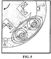
- the Stator 42 In the presence of an electrical load or loads, the Stator 42 carries its normal current. It produces a strong magneto-motive force that, if it acted alone, would create flux ⁇ 2 as shown in Fig 5 .
- Stage 1 is a typical Faraday Law of electromagnetic induction from the Rotor 43 to Stator 42 and the magnetic flux is directed from Rotor 43 to Stator 42 as shown in Fig 4 .
- Stage 2 additional magnetic flux from current flow (due to the presence of an external load) in the coil means of Stator 42 is directed from Stator 42 to Rotor 43 as shown in Fig 5 .
- Stage 3 the magnetic flux from Stage 1 interacts with the additional flux from Stage 2 to form a strong resultant magnetic flux (or magnetic flux density with symbol B) that is directed from Rotor 43 to Stator 42 as shown in Figure 6 .
- this incident magnetic field causes transitions between two energy levels in a magnetic atom where the transition is from E1 to E0 with additional identical and coherent magnetic fields radiated to trigger other magnetic atoms.
- the discrete energy level between E1 and E0 means that a magnetic atom can only absorb or emit energy in definite amounts and not continuously. This explains why the external applied magnetic field must be of a certain and narrow range.
- the magnetic energy associated with the enhanced magnetic field is being absorbed and converted into electrical energy by the Stator 42's windings, resulting in more electrical power being generated (in the presence of electrical loads) as compared with the input power supplied to the Prime Mover 20.
- the "extra" AC power generated is in phase with each other and is of the same frequency (50 Hz or 60 Hz).
- the generated AC output power is clean and not noisy.
- the strong magnetic flux (generated in Stage 3) from each pole of Rotor 43 is a thin beam when view from the cross-sectional side of Electrical Generator 40 and as a uniform plane beam when view from the elongated side of Electrical Generator 40.
- the coil means of Stator 42 are subjected to such a strong and uniform magnetic flux, multi-stranded copper wires that are small, untwisted and parallel to each other are used as shown in Fig. 8 .
- the use of small and circular cross-sectional wire as compared with a single circular wire or a single flat wire has the advantage of having more surface area for AC current transmission.
- Each wire is insulated via enamel coating.
- Stator 42 is made of magnetic material or any alloy that can be stimulated by metamagnetic effect relative to the magnetic material used in Rotor 43.
- Metamagnetic effect is a physical state of matter (such as the magnetic material of Stator 42) characterized by a super-linear increase of magnetization (stimulated emission of magnetic fields within that matter) over a narrow range of an external applied magnetic field (brought about by Magnetic Flux ⁇ 3 at region A in Fig. 6 ).
- the characteristic feature of Stator 42 's magnetic material is due to the presence of magnetic domains.
- a magnetic domain is a region of crystalline matter, whose volume may be between 10 -12 and 10 -8 m 3 , which contains atoms whose magnetic moments are aligned in the same direction.
- the magnetic moment of a magnetic atom results from the spin of electrons in an unfilled inner shell of the atom.
- the formation of a magnetic domain depends upon the strong inter-atomic forces (exchange forces) that are effective in a crystal lattice containing magnetic atoms.
- the magnetic domains are arranged in a random fashion with their magnetic axes pointing in all directions so that the specimen has no resultant magnetic moment.
- a very strong applied magnetic field triggers stimulated emission within the Stator 42's specimen.
- Fig. 7 shows the transitions between two energy levels in a magnetic atom by stimulated emission, in which an incident magnetic field (symbol H) causes a transition from E1 to E0.
- an incident magnetic field symbol H
- the radiated magnetic fields are exactly in phase with the incident ones, so the result is an enhanced beam of coherent magnetic fields and these coherent magnetic fields are converted instantaneously into a strong current flow in Stator 42's windings via the application of Ampere's law.
- the magnetic energy associated with the enhanced magnetic field is being absorbed and converted into electrical energy by the Stator 42's windings, resulting in more electrical power is being generated (in the presence of electrical loads) as compared with the input power supplied to the Prime Mover 20.
- the enhanced beam of coherent magnetic field enables the present invention to be used as a device for power stability in an electrical distribution network or in a national grid.
- the coherent nature of enhanced magnetic field enables additional electrical power to be generated with no change in phase angle or frequency (50 Hz or 60 Hz). In this way, unanticipated output can be catered for and at the same time, unexpected power trip due to power instability can be avoided.
- Rotor 43 is made of magnetic material that is invariant to metamagnetic effect.
- the enhanced magnetic flux in Stator 42 causes saturation to set in pole tip of region A.
- the increase of flux under the left side of the pole, region A is only slightly more than the flux when the Meta-magnetic Effect does not take place. Consequently, the magneto-motive force does not increase appreciably in the presence of strong magnetic flux within the Stator 42 at region A, resulting in a constant rotating speed of Rotor 43 that does not increase with electrical loads.
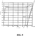
- Fig. 9 shows the characteristics of a particular conjugate pair of magnetic material that is applicable for the Electrical Generator 40.
- the magnetic material used in the magnetising means must be non-metamagnetic relative to the regions entering the metamagnetic state.
- Non-metamagnetic material is characterized by adoption of magnetic material such as "Permalloy” with high relative permeability (with curve originated more to the left of Fig 9 ) and its magnetic flux density must be saturated prior and during the regions of the other part with coil means (that uses "Alnico V”) entering a metamagnetic state.
- Rotor 43 is said to be “isolated” from the excessive magnetic flux across the narrow air gap between each pole and its adjacent Stator's region.
- Other conjugate pairs such as “Permalloy and Stelloy”, “Silcon Iron and Alnico V”, “Silicon Iron and Stelloy”, “Pure Iron and Alnico V”, “Pure Iron and Stelloy” are applicable in this regard.
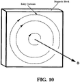
- Eddy currents can be reduced tremendously by splitting the magnetic block into thin and insulated laminations as shown in Fig. 11 .
- the voltage induced is also a fraction of that induced in the entire block, with the result that the eddy currents and the corresponding losses are considerably reduced.
- the eddy-current losses decrease in proportion to the square of the number of laminations.
- the magnetic structures of both Rotor 43 and Stator 42 are composed of stacked laminations with a fraction of a millimetre thick. Epoxy/resin is the insulating material used by these laminations.
- conveyor-Belt System 30 ensures the input power of the present invention is electrically isolated from its output power.
- Exciter 50 is driven mechanically by Conveyor-belt 33 from Shaft 41 of Meta-magnetic Effect Dynamo 40.
- Shaft 41 of Meta-magnetic Effect Dynamo 40 is in turn driven mechanically by Conveyor-belt 32.
- Exciter 50 does not use the electrical output power of Stator 42.
- the fact that magnetic saturation sets in at the tip of each pole during Meta-magnetic Effect means that apart from the magneto-motive force needed to turn the Rotor 43, Rotor 43 is "isolated” from excess magnetic flux across the narrow air gap between the each pole and its adjacent Stator 42's region.
- two electrical reference frames are established, one is DC Circuit (that includes Exciter 50 and Rotor 43) for generating the Magneto-motive Force needed by Rotor 43, and the other is the three-phase AC Circuit (that includes the Stator 42's windings and external loads) for generating the Electric Output Power needed by external electrical loads.
- DC Circuit that includes Exciter 50 and Rotor 43
- the three-phase AC Circuit that includes the Stator 42's windings and external loads
- the electrical isolation brought about by the establishment of two electrical reference frames also enables a plurality of single systems or integrated systems to increase the power or to provide power stability in each part of an electrical distribution network or a national grid.
- Table 1 illustrates a set of measurement data of an electricity generation system according to this first embodiment of the present invention.
- Steps 1 to 4 are the initialisation steps needed to power up the electricity generation system.
- Steps 4 to 8 illustrate the "Power Stability Zone" of Generator 40.
- the angular velocity of the rotor 43 and thereby the frequency of the generated electrical current remains substantially constant under different load conditions. It is important to note that in this zone, there is no need to control the speed of Prime Mover 20 to match the variations in external electrical load connected to the output cables of Electrical Generator 40. In fact, no external control is needed in this zone, the metamagnetic interaction within Stator 42 responds to the variations of external electrical load directly. Besides, further cooling is not needed when operating in Power Stability Zone as both the Prime Mover 20 and Rotor 43 of Electrical Generator 40 are running at their normal and steady speed
- Step 9 to 11 illustrates the "Power Enhancement Zone" of Generator 40.
- additional power is needed by Prime Mover 20 in order to maintain the angular velocity of the rotor 43 with respective to increasing load at output of Generator 40.
- Fig. 12 wherein the electricity generation system 11, according to another embodiment of the present invention is shown.
- the system includes Prime Mover 20, Transmission Assembly 70, Electrical Generator in the form of a Meta-magnetic Effect Dynamo 40, Exciter 50, Platform 60, and a Control Unit with touch-screen display 80.
- Prime Mover 20 is an AC (Alternating Current) Motor.
- the alternating current (AC) provided from an external power source is used to generate a mechanical torque by means of a rotating magnet in a coil of wire, or by a rotating coil of wire inside a powerful magnet. In either case, the generated mechanical torque is used to rotate the Shaft 21 of Prime Mover 20.
- Prime Mover 20 receives its AC input power via Input Power Cables 22 (Live L1), 23 (Live L2) and 24 (Live L3). While only one type of Prime Mover 20 is shown, in reality, the Prime Mover 20 can be a single phase Alternating Current (AC) Motor or a DC (Direct Current) Motor with a DC to AC Converter for its electrical input power.
- AC Alternating Current
- DC Direct Current
- the Input Power Cables 22 (Live L1), 23 (Live L2) and 24 (Live L3) of Prime Mover 20 can be connected to an external generator such as a fossil fuel-fired steam turbine, natural gas-fired steam turbine, a hydro-generator, a diesel engine, a petrol engine, a steam engine, a Fuel-cell Generator, an AC or DC generator that uses alternative sources of energy (such as solar, wind, hydro-electric, wave energy, or biomass), and any electricity generation unit that can provide the required AC or DC power to drive Prime Mover 20 used in the present invention.
- an external generator such as a fossil fuel-fired steam turbine, natural gas-fired steam turbine, a hydro-generator, a diesel engine, a petrol engine, a steam engine, a Fuel-cell Generator, an AC or DC generator that uses alternative sources of energy (such as solar, wind, hydro-electric, wave energy, or biomass), and any electricity generation unit that can provide the required AC or DC power to drive Prime Mover 20 used in the present invention.
- Prime Mover 20 does not develop its full power when it is running slowly. It has to be rotating fairly fast before it develops its maximum power and torque.
- the Transmission Assembly 70 provides a mean to allow the Shaft 21 of Prime Mover 20 to revolve at high speed to produce the desired power on one hand and allow its Output Shaft 74 to turn at slower speed on the other hand to ensure Shaft 41 of Meta-magnetic Effect Dynamo 40 turns at 25 Hz or 30 Hz (due to the use of a four-pole Rotor that provides two cycles of voltage per revolution). The speed reduction is achieved via the Planetary Gear Set 73.
- Shaft 21 of Prime Mover 20 is connected to Shaft 72 of Torque Converter 71.
- Torque Converter 71 serves as a fluid coupling device and it offers the following advantages: [a] Absence of direct mechanical contact between the driving and driven members minimizes the transmission of shock and torsional vibration between Prime Mover 20 and Transmission Assembly 70; [b] no positive disengagement or engagement of drive allows smoother starting characteristic; [c] protects against harmful labouring of Prime Mover 20 at low speed, since the fluid coupling will merely slip and allow Prime Mover 20 to increase speed when overloaded.
- the Output Shaft 74 is coupled to Shaft 41 of Meta-magnetic Effect Dynamo 40.
- Power Take Off (PTO) 75 is coupled to Shaft 51 of Exciter 50.
- Electronic Assembly (EA) 77 also known as Transmission Control Unit, is the brain of Transmission Assembly 70. It is connected to Transmission Assembly 70 via a Signal Cable 76. While only one type of Transmission Assembly 70 is shown, in reality, Transmission Assembly 70 can be manual, semi-automatic, or fully automatic. Transmission Assembly 70 also includes system that uses Frictional Clutch instead of Torque Converter 71. Transmission Assembly 70 can also have two or more PTOs 75 in its construction.
- Exciter 50 is an Alternator that generates the DC power needed by Meta-magnetic Effect Dynamo 40. It consists of three major components: the rotor, the stator, and the rectifier bridge with regulator.
- the principle of AC generation in Alternator is motion between magnetic lines of force, and conductors will induce electrical pressure (AC Voltage).
- AC Voltage electrical pressure
- the rotor will supply the magnetic lines of force
- PTO 75 spinning the rotor will supply the motion.
- the generated AC power is converted into DC power by the rectifier bridge with regulator.
- DC Power generated is supplied to Meta-magnetic Effect Dynamo 40 via Output Power Cable 53 (Positive DC Voltage) and Output Power Cable 52 (Ground). While only one type of Exciter 50 is shown, in reality, Exciter 50 can be any DC Power Source such as a battery or a fuel cell.
- Meta-magnetic Effect Dynamo 40 is a synchronous machine that is driven by Output Shaft 74 of Transmission Assembly 70. It uses Meta-magnetic Effect to generate power from within the magnetic structure of its Stator 42.
- Fig. 2 shows a perspective cross-sectional schematic view of Meta-magnetic Effect Dynamo 40.
- the stationary part that is essentially a hollow cylinder, called the Stator 42 has longitudinal slots in which there are coils of Stator 42's windings. These windings carry the current supplied to an electrical load.
- Rotor 43 is the part of the machine that is mounted on the shaft and rotates inside the hollow Stator 42.
- the winding on Rotor 43 called the field winding, is supplied with DC current from Exciter 50 via Output Power Cable 53 (Positive Voltage) and Output Power Cable 52 (Ground).
- Rotor 43 is a single, longitudinal block with a uniform four-pole cross section area as shown in Fig. 8 .
- the enhanced beam of coherent Magnetic Field generated via metamagnetic interaction is converted into a strong current flow in Stator 42's Windings instantaneously.
- This strong instantaneous current flow enables the present invention to be used as a device for power stability in an electrical distribution network or in a national grid.
- the coherent nature of enhanced Magnetic Field enables additional electrical power to be generated with no change in phase angle or frequency (50 Hz or 60 Hz) and no change in output voltage. In this way, unanticipated output can be catered for and at the same time, unexpected power trip due to power instability can be avoided.
- three-phase AC power is being generated and can be supplied to external loads via Output Power Cable 44 (Live L1), Output Power Cable 45 (Live L2), Output Power Cable 46 (Live L3), and Output Power Cable 47 (Neutral).
- Output Power Cable 44 Live L1
- Output Power Cable 45 Live L2
- Output Power Cable 46 Live L3
- Output Power Cable 47 Netral
- Control Unit with a touch-screen display 80 is the main brain for the electricity generation system 11. It is used for controlling the operations of the present invention such as the powering up sequence, and the shutting down sequence.
- the Control Unit has two communication ports with each support either RS-232C or RS-485 communication protocol. One port is used to input control sequence by connecting it to a Personal Computer or Laptop. The other is used to communicate with Electronic Assembly 77 of Transmission 70 via additional communication protocols such as SAE J1708, SAE J1587, SAE J1939, and CAN-bus Protocol.
- Fig. 13 shows a flow chart of the operation of the Control Unit with a touch-screen display 80.
- Control Unit 80 Upon power up, in step S100, Control Unit 80 performs an initialization in step S110 and waits for button click from its touch screen in step S120.
- EA response message for successful neutral engagement in step S140.
- When valid response is received in S140 it issues a discrete signal to activate a Relay or a Switchgear in order to power up Prime Mover 20 in step S150. It waits for the required rpm value to attain in step S160.
- Control Unit 80 sends a request command to Electronic Assembly 77 in step S 170 to shift Transmission Assembly 70 to Drive Mode. It waits for Output Shaft 74 to attain the required rpm value (25 Hz or 30 Hz due to the use of a four-pole Rotor that provides two cycles of voltage per revolution) in step S180. When the required rpm value for Output Shaft 74 is verified, it sends a request command to Electronic Assembly 77 in step 190 to engage PTO 75 in order to drive the Exciter 50.
- the Meta-magnetic Effect Generator 11 is fully functional after this step.
- Control Unit 80 Upon receiving a Power-OFF button click from its touch-screen display in step S120, Control Unit 80 sends a request command to Electronic Assembly 77 in step S200 to disengage PTO 75 in order to stop Exciter 50 from operating. It waits for EA response message for successful PTO disengagement in step S210. When valid response is received in step S210, it sends request command to EA 77 in step S220 to shift Transmission Assembly 70 to Neutral Mode and waits for valid response in step S230. When valid response is received in step S230, it issues a discrete signal to deactivate a Relay or a Switchgear to cut-off input power supply to Prime Mover 20 in step S240.
- a more efficient approach for Power-OFF is to insert a Relay or Switchgear between Output Power cable 53 and Output Power Cable 52 (not shown in diagram) as well as to include in step S200 an additional task of sending a discrete signal to disengage the Relay or Switchgear prior to the request command for disengaging PTO 75. In this manner, instantaneous power cut-off can be achieved in this present invention.
- Control Unit 80 is mainly used for system start-up and shut down. It can also be used to match variations in external load when the system is not operating in Power Stability Zone. Control Unit 80 monitors variations in external load via changes in the required Drive Mode rpm value for Output Shaft 74. Upon receiving a Load-variation button click from its touch-screen display in step S120, it sends a request command to Electronic Assembly 77 in step S300 for the Drive Mode rpm value of Output Shaft 74. It waits for EA response message for Drive Mode rpm value in step S310. If valid rpm value is obtained in S310, it returns to step S120 to check whether Load-variation is still activated.
- step S320 to issue a discrete signal, an analog signal, or a command to the AC Power Source that is connected to the input power cables of Prime Mover 20 and instructs the AC Power Source to either increase or reduce the power supply to Prime Mover 20 in response to the load variations. It then returns to step S120 to check whether Load-variation button is still activated. If Load-variation button is still activated, steps S120, S300, S310, and S320 are repeated until the required Drive Mode rpm value for Output Shaft 74 is established and maintained.
- Transmission Assembly 70 ensures the input power of the present invention is electrically isolated from its output power.
- Exciter 50 is driven mechanically by PTO 75.
- Shaft 41 of Meta-magnetic Effect Dynamo 40 is in turn driven mechanically by Output Shaft 74.
- Exciter 50 does not use the electrical output power of Stator 42.
- the fact that magnetic saturation sets in at the tip of each pole during Meta-magnetic Effect means that apart from the magneto-motive force needed to turn the Rotor 43, Rotor 43 is "isolated” from excess magnetic flux across the narrow air gap between the each pole and its adjacent Stator 42's region.
- two electrical reference frames are established, one is DC Circuit (that includes Exciter 50 and Rotor 43) for generating the Magneto-motive Force needed by Rotor 43, and the other is the three-phase AC Circuit (that includes the Stator 42's windings and external loads) for generating the Electric Output Power needed by external electrical loads.
- DC Circuit that includes Exciter 50 and Rotor 43
- the three-phase AC Circuit that includes the Stator 42's windings and external loads
- Fig. 14 wherein the electricity generation system 12, according to a further embodiment of the present invention is shown.
- the system includes Prime Mover 20, Gear Train Assembly 90 (with three Gears 91, 92, and 93), Electrical Generator in the form of a Meta-magnetic Effect Dynamo 40, Exciter 50, Platform 60, and a Control Unit with touch-screen display 80.
- Prime Mover 20 is an AC (Alternating Current) Motor.
- the alternating current (AC) provided from an external power source is used to generate a mechanical torque by means of a rotating magnet in a coil of wire, or by a rotating coil of wire inside a powerful magnet. In either case, the generated mechanical torque is used to rotate the Shaft 21 of Prime Mover 20.
- Prime Mover 20 receives its AC input power via Input Power Cables 22 (Live L1), 23 (Live L2) and 24 (Live L3). While only one type of Prime Mover 20 is shown, in reality, the Prime Mover 20 can be a single-phase Alternating Current (AC) Motor or a DC (Direct Current) Motor with a DC to AC Converter for its electrical input power.
- AC Alternating Current
- DC Direct Current
- the Input Power Cables 22 (Live L1), 23 (Live L2) and 24 (Live L3) of Prime Mover 20 can be connected via an AC Input Power Switch Box 25 to an external generator such as a fossil-fired steam turbine, natural gas-fired steam turbine, a hydro-generator, a diesel engine, a petrol engine, a steam engine, a Fuel-cell Generator, an AC or DC generator that uses alternative sources of energy (such as solar, wind, hydro-electric, wave energy, or biomass), and any electricity generation unit that can provide the required AC or DC power to drive Prime Mover 20 used in the present invention.
- an external generator such as a fossil-fired steam turbine, natural gas-fired steam turbine, a hydro-generator, a diesel engine, a petrol engine, a steam engine, a Fuel-cell Generator, an AC or DC generator that uses alternative sources of energy (such as solar, wind, hydro-electric, wave energy, or biomass), and any electricity generation unit that can provide the required AC or DC power to drive Prime Mover 20 used in the present invention
- Gear Train Assembly 90 provides a mechanical mean to connect Shaft 21 of Prime Mover 20 to Shaft 41 of Meta-magnetic Effect Dynamo 40. Its gear ratio enables Shaft 21 of Prime Mover 20 to revolve at high speed to produce the desired power on one hand and allow Shaft 41 of Meta-magnetic Effect Dynamo 40 to turn at slower speed at 25 Hz or 30 Hz (due to the use of a four-pole Rotor that provides two cycles of voltage per revolution).
- Gear 92 is threaded firmly and secured by a lock nut to the Shaft 21 of Prime Mover 20. Therefore, at system start-up, Prime Mover 20 and its Shaft 21 must be strong enough to overcome the inertia of Gear Train 90, inertia of Shaft 51 of Exciter 50, and inertia of Shaft 41 of Meta-magnetic Effect Dynamo 40 directly without slip. To prevent Shaft 21 of Prime Mover 20 from being twisted or breaking at start-up, Single Plate Clutch 100 may be deployed to connect Shaft 21 to Gear 92.
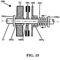
- Single Plate Clutch 100 is a device used to engage Shaft 21 and Gear 92 smoothly in relative motion during system start-up. It comprises a Friction Plate 101, a Pressure Plate 102, a Spring 103, and two Guards 104a and 104b. Both Guards are attached and secured firmly to the Shaft 21. Guard 104a is used to hold the Spring 103 in place and Guard 104b is used to hold Gear 92 in place. Shaft 21 serves as the driving member that is driven permanently by Prime Mover 20. Pressure Plate 102 rotates permanently with Shaft 21. It supplies the other unlined friction contact surface, and conveys the clamping force of Spring 103 to Shaft 21. Friction Plate 101 is the driven member.
- Gear 92 To accommodate wearing of the friction-lined Friction Plate 101 and the slip during system start-up, a certain amount of axial freedom must be provided for Gear 92. This axial freedom is achieved by attaching Gear 92, Friction Plate 101, and Pressure Plate 102 to Shaft 21 with Bush Bearing 105c, 105b, and 105a respectively so that they can float along Shaft 21 between the two Guards 104b and 104a.
- Pressure Plate 102 is produced from cast iron and is intentionally of rugged construction, it must neither distort under the loading of Spring 103 nor be unable to absorb and conduct away the heat generated during clutch engagement. Spring 103 is compressed between Pressure Plate 102 and Guard 104a.
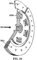
- Fig. 16 shows the construction of Friction Plate 101.
- Friction Plate 101 Each side of Friction Plate 101 is faced with a ring of friction material, known as Friction Lining 101c, which is secured by riveting to Borglite Segment 101 a.
- Torsional Damper-springs 101b are provided to permit smooth, gradual engagement.
- Fig. 15 the purpose of fitting a Single Plate Clutch provides the following benefits: [a] Better engagement at system start-up, slight delay in the form of slip before full engagement enables Prime Mover 20 to have sufficient time to build up it speed, thereby, allowing shock-free connection between Shaft 21 and Gear 92; [b] the friction linings 101 c enables maximum torque transmission from Shaft 21 to Gear 92 at full engagement.
- Exciter 50 is an Alternator that generates the DC power needed by Meta-magnetic Effect Dynamo 40. It consists of three major components: the rotor, the stator, and the rectifier bridge with regulator.
- the principle of AC generation in Alternator is motion between magnetic lines of force, and conductors will induce electrical pressure (AC Voltage).
- AC Voltage electrical pressure
- the rotor will supply the magnetic lines of force
- Gear 91 spinning the rotor will supply the motion.
- the generated AC power is converted into DC power by the rectifier bridge within the regulator.
- Exciter 50 can be any DC Power Source such as a battery or a fuel cell.
- Meta-magnetic Effect Dynamo 40 is a synchronous machine that is driven by Gear 93 of Gear Train Assembly 90. It uses Meta-magnetic Effect to generate power from within the magnetic structure of its Stator 42.
- Fig. 2 shows a perspective cross-sectional schematic view of Meta-magnetic Effect Dynamo 40.
- the stationary part that is essentially a hollow cylinder, called the Stator 42 has longitudinal slots in which there are coils of Stator 42's windings. These windings carry the current supplied to an electrical load.
- Rotor 43 is the part of the machine that is mounted on the shaft and rotates inside the hollow Stator 42.
- the winding on Rotor 43 called the field winding, is supplied with DC current from Exciter 50 via Output Power Cable 53 (Positive DC Voltage) and Output Power Cable 52 (Ground).
- Rotor 43 is a single, longitudinal block with a uniform four-pole cross sectional area as shown in Fig. 8 .
- the enhanced beam of coherent Magnetic Fields generated via metamagnetic interaction is converted into a strong current flow in Stator 42's Windings instantaneously.
- This strong instantaneous current flow enables the present invention to be used as a device for power stability in an electrical distribution network or in a national grid.
- the coherent nature of enhanced Magnetic Field enables additional electrical power to be generated with no change in phase angle or frequency (50 Hz or 60 Hz) and no change in output voltage. In this way, unanticipated output can be catered for and at the same time, unexpected power trip due to power instability can be avoided.
- three-phase AC power is being generated and can be supplied to external loads via Output Power Cable 44 (Live L1), Output Power Cable 45 (Live L2), Output Power Cable 46 (Live L3), and Output Power Cable 47 (Neutral).
- Output Power Cable 44 Live L1
- Output Power Cable 45 Live L2
- Output Power Cable 46 Live L3
- Output Power Cable 47 Netral
- Control Unit with a touch-screen display 80 is the main brain for the electricity generation system 12. It is used for controlling the operations of the present invention such as the powering up sequence, and the shutting down sequence.
- the Control Unit has two communication ports with each support either RS-232C or RS-485 communication protocol. One port is used to input control sequence by connecting it to a Personal Computer or Laptop. The other is used to communicate with the AC Power Source that is connected to Prime Mover 20.
- Control Unit 80 is connected to DC Output Power Switch Box 54 via Signal Cable 81.
- a Relay switch is installed (not shown in Fig 14 ) inside the DC Output Power Switch Box 54.
- the Signal Cable 81 is connected to the DC Output Power Switch Box 54 via a Switchgear.
- Control Unit 80 is connected to AC Input Power Switch Box 25 via Signal Cable 82.
- a Relay Switch (not shown in Fig 14 ) and an AC to DC power converter (not shown in Fig 14 ) are installed inside the AC Input Power Switch Box 25.
- Control Unit 80 also receives DC input power from Signal Cable 82 from the AC to DC Power Converter installed inside the AC Input Power Switch Box 25.
- Fig. 17 shows a flow chart of the operation of the Control Unit with a touch-screen display 80.
- Control Unit 80 Upon power up, in step S100, Control Unit 80 performs an initialisation in step S110 and waits for button click from its touch screen in step S120.
- step S 150 When the desired speed for Shaft 41 is obtained, it issues a discrete signal via Signal Cable 81 in step S 150 to energise the Relay Switch in DC Output Power Switch Box 54 (or Switchgear) to supply DC power via Power Cable 53 (Positive DC Voltage) and Power Cable 54 (Ground) to enable Faraday's Law of Electromagnetic Induction to take place inside Meta-magnetic Effect Dynamo 40.
- the Meta-magnetic Effect Generator 12 is fully functional after this step.
- Control Unit 80 Upon receiving a Power-OFF button click from its touch-screen display in step S120, Control Unit 80 sends a discrete signal via Signal Cable 81 in step S200 to DC Output Power Switch Box 54 to deactivate the Relay Switch (or Switchgear) in order to cut off the DC supply which in turn disables the Meta-magnetic Effect Dynamo instantly as Faraday's Law of Electromagnetic Induction cannot take place immediately after that instance. It then issues a discrete signal via Signal Cable 82 in step S210 to AC Input Power Switch Box 25 to deactivate the Relay Switch in order to power off Prime Mover 20. Control Unit 80 continues to receive its DC power from the AC to DC Converter installed inside the AC Input Power Switch Box 25.
- Control Unit 80 is mainly used for system start-up and shut down. It can also be used to match variations in external load when the system is not operating in Power Stability Zone. Control Unit 80 monitors variations in external load via changes in the required rpm value for Output Shaft 93. Upon receiving a Load-variation button click from its touch-screen display in step S120, it reads the RPM reading of Shaft 51 and derives the speed of Shaft 41 from the received rpm reading via gear-ratio conversion in step S300. If valid rpm value is obtained in S300, it returns to step S 120 to check whether Load-variation is still activated.
- step S310 If Load-variation button is still activated, steps S120 and S300 are repeated for ongoing monitoring of the rpm value for Shaft 93.
- variation is detected in S300, it enters step S310 to issue a discrete signal, an analog signal via an additional Signal Cable (not shown in Fig. 14 ), or a command via the second serial communication port (not shown in Fig. 14 ) to an External AC Power Source that is connected to the input power cables of Prime Mover 20 and instructs the AC Power Source to either increase or reduce the power supply to Prime Mover 20 in response to the load variations.
- step S120 checks whether Load-variation button is still activated. If Load-variation button is still activated, steps S120, S300, and S310 are repeated until the required rpm value for Shaft 93 is established and maintained.
- Gear Train Assembly 90 as a whole ensures the input power of the present invention is electrically isolated from its output power.
- Exciter 50 is driven mechanically by Gear 91.
- Shaft 41 of Meta-magnetic Effect Dynamo 40 is in turn driven mechanically by Gear 93.
- Exciter 50 does not use the electrical output power of Stator 42.
- the fact that magnetic saturation sets in at the tip of each pole during Meta-magnetic Effect means that apart from the magneto-motive force needed to turn the Rotor 43, Rotor 43 is "isolated” from excess magnetic flux across the narrow air gap between the each pole and its adjacent Stator 42's region.
- two electrical reference frames are established, one is DC Circuit (that includes Exciter 50 and Rotor 43) for generating the Magneto-motive Force needed by Rotor 43, and the other is the three-phase AC Circuit (that includes the Stator 42's windings and external loads) for generating the Electric Output Power needed by external electrical loads.
- DC Circuit that includes Exciter 50 and Rotor 43
- the three-phase AC Circuit that includes the Stator 42's windings and external loads
Landscapes
- Engineering & Computer Science (AREA)
- Power Engineering (AREA)
- Connection Of Motors, Electrical Generators, Mechanical Devices, And The Like (AREA)
- Iron Core Of Rotating Electric Machines (AREA)
- Control Of Eletrric Generators (AREA)
Claims (13)
- Un générateur électrique (40) comprenant un stator (42) composé au moins en partie d'un matériau ayant des propriétés méta-magnétiques et ayant des passages de bobine reliés à une charge électrique externe, et un rotor (43) ayant un électro-aimant pour générer un champ magnétique dans celui-ci, le déplacement du rotor et du champ magnétique par rapport au stator, induisant un écoulement de courant électrique dans le passage de bobine, l'électro-aimant configuré pour générer un champ magnétique de résistance pour interagir avec un champ magnétique associé à la charge électrique externe et induire le méta-magnétisme dans le matériau méta-magnétique du stator pour augmenter l'écoulement de courant électrique à l'intérieur des passages de bobine.
- Un générateur électrique (40) selon la revendication 1, dans laquelle le rotor (43) est composé au moins en partie d'un autre matériau aux propriétés non méta-magnétiques, ou dans laquelle l'autre matériau a une perméabilité magnétique plus élevée que le matériau méta-magnétique, ou dans laquelle l'autre matériau présente une densité de flux magnétique saturée, indépendamment du fait que le matériau méta-magnétique du stator (42) ait ou non un méta-magnétisme induit dans celui-ci, ou dans laquelle l'autre matériau est un ou plusieurs de Permalloy, Fer de Silicium, Fer Pur, Relais Acier ou un Fer Equivalent.
- Un générateur électrique (40) selon la revendication 1 ou 2, dans laquelle la vitesse angulaire du rotor (43) et donc de la fréquence générée du courant électrique, reste sensiblement constante malgré l'induction de méta-magnétique dans le matériau méta-magnétique du stator (42), ou dans laquelle l'électro-aimant comprend des premières et secondes paires de polaires diamétralement opposées, ou dans laquelle les pôles ont une section transversale qui applique un faisceau de flux magnétiques de chaque pôle lorsque le rotor est vu en plan et un uniforme lorsque le rotor est vu en élévation.
- Un générateur électrique (40) selon l'une quelconque des revendications 1 à 3, dans lesquelles le stator (42) est un cylindre sensiblement creux avec les passages de bobine prévus à des emplacements sélectionnés sur la paroi intérieure de celui-ci ; ou dans lesquelles les passages de bobine sont prévus dans des fentes s'étendant longitudinalement formées dans la paroi intérieure du creux cylindre, ou dans lequel les passages de bobine sont connectés de manière fonctionnelle ou de manière à générer le courant alternatif d'une phase sélectionnée, ou dans lesquelles les passages de bobine comprennent des fils multibrins parallèles, isolés, non torsadés, minces et circulaires situés à l'intérieur des fentes s'étendant d'une manière longitudinalement telle que chaque fil est soumis à un flux magnétique uniforme, ou dans lesquelles les passages de bobine sont fonctionnellement reliés de façon à générer indépendamment et simultanément le courant alternatif de deux ou plusieurs phases sélectionnées en réponse à deux ou davantage de charges électriques externes correspondantes.
- Un système de génération d'électricité (10) comprenant :un générateur électrique (40) selon l'une quelconque des revendications 1 à4;des passages d'alimentation en énergie pour fournir de l'énergie magnétique àl'électro-aimant et de l'énergie mécanique au rotor (43), ladite énergie magnétique et mécanique étant fournie au générateur indépendamment du courant électrique généré par le générateur.
- Un système de génération d'électricité (10) selon la revendication 5, dans laquelle l'énergie d'alimentation comprend :un moteur ; etun montage ceinturier reliant fonctionnellement le rotor (43) au moteur,le mouvement de rotation du moteur étant transféré au rotor l'intermédiaire du montage de la courroie, ouun montage de transmission (70) reliant fonctionnellement le rotor au moteur, le mouvement de rotation du moteur étant transféré au rotor par l'intermédiaire du montage de la transmission, ouUn montage de train d'engrenages (90) reliant de manière opérationnelle le rotor au moteur,Le mouvement de rotation du moteur étant transféré au rotor par l'intermédiaire du train d'engrenages monté ;une source de DC continu commandée par le montage de train d'engrenages ; etun interrupteur à relais ou un tableau de commutation reliant l'électro-aimant la source de DC.
- Un système de génération d'électricité (10) selon la revendication 5 ou 6, comprenant en outre un dispositif de réglage (36) pour relier le montage ceinturier, le train d'engrenages (90) ou de transmission (70), au moteur de façon à surmonter l'inertie de l'élément mobile pendant le démarrage du système, ou dans lequel l'ajusteur est un embrayage qui est configuré pour engager sélectivement ou désengager le moteur vers et à partir du montage ceinturier, l'embrayage ou montage de transmission, ou dans lequel l'embrayage est un seul embrayage à plaques.
- Un système de génération d'électricité (10) selon la revendication 5 ou 6, comprenant en outre un contrepoids dans le montage ceinturier, un train d'engrenages (90) ou un montage de transmission (70) pour assurer que les parties mobiles sont dans un équilibre statique et dynamique et lisser toute secousse rencontrée lors du mouvement de pièces mobiles.
- Un système intégré de production d'électricité comprenant au moins deux ou davantage de systèmes de génération d'électricité fonctionnellement connectés (10) selon la revendication 5 ou 6, en vue d'augmenter la puissance électrique d'une seule unité et / ou de fournir une stabilité sélectionnée du réseau de distribution électrique, ou dans lequel la génération d'électricité est montée en cascade en série et / ou connectée en parallèle.
- Un générateur électrique (40) selon l'une quelconque des revendications 1 à 5 dans laquelle le générateur électrique est rangé pour induire le méta-magnétisme entre les matériaux méta-magnétiques du stator (42) en utilisant un processus instantané à cinq niveaux pour augmenter de manière spontanée et cohérente l'écoulement du courant électrique entre les passages de bobine et dans lesquels le processus instantané à cinq niveaux est compris :(i) un premier niveau comprenant un flux magnétique de direction à partir du rotor (43) au stator en accord avec la Loi de Faraday sur l'Induction Electromagnétique ;(ii) le second niveau comprenant un flux magnétique additionnel de direction à partir de l'écoulement du courant dans les passages de bobine au regard de la présence de la charge électrique externe du rotor au stator ;(iii) un troisième niveau comprenant la formation d'un flux magnétique de forte résultante dirigée à partir du rotor au stator pour pénétrer le stator, en interagissant le flux magnétique à partir du premier niveau avec le flux additionnel à partir du second niveau ;(iv) un quatrième niveau, comprenant la génération d'un fort faisceau lumineux de champs magnétiques cohérents immédiatement dans le matériau, par la résultante de champs magnétiques poussant le matériau du stator revêtir des propriétés méta-magnétiques dans l'état méta-magnétique et à relâcher des champs magnétiques cohérents additionnels qui occasionnent des émissions similaires dans d'autres atomes magnétiques dans le matériau ; et(v) un cinquième niveau comprenant la transformation instantanée du fort faisceau lumineux de champs magnétiques cohérents générés dans le matériau du stator dans le niveau 4 dans un fort écoulement de courant dans les passages de bobine du stator, en accord à la Loi d'Ampère.
- Un générateur électrique (40) selon la revendication 10 dans laquelle le générateur électrique est rangé pour arrêter instantanément l'augmentation cohérente et spontanée de l'écoulement du courant électrique dans les passages de bobine en désactivant un disjoncteur ou un stoppeur de vitesse pour terminer l'alimentation électrique à l'électro-aimant malgré le mouvement progressif du rotor (43).
- Un système de génération électrique (10) selon une quelconque des revendications 5 à 9, incluant en outre une unité de contrôle pour le démarrage et l'arrêt du système, et pour identifier les variations dans la charge électrique externe quand le système n'est pas en marche dans une Zone de Stabilité d'Energie, dans laquelle, dans la Zone de Stabilité d'Energie, la vitesse angulaire du rotor reste substantiellement constante sous différentes conditions de charge, ou incluant en outre des ceintures additionnelles respectives dans le montage ceinturier, les cames dans le montage de transmission (70), et engrenages additionnels dans le montage du train d'engrenage (90), permettant au moteur d'entrainer deux ou plus de générateurs (40) par rapport à une quelconque des revendications 1 à 4.
- Un engin auto-motif ou un tube marin utilisant un engin auto-motif incluant un ou plus de générateurs électriques (40) selon une quelconque des revendications 1 à 4.
Applications Claiming Priority (2)
| Application Number | Priority Date | Filing Date | Title |
|---|---|---|---|
| PCT/SG2008/000169 WO2009136864A1 (fr) | 2008-05-06 | 2008-05-06 | Générateur électrique et système de génération électrique |
| PCT/SG2009/000028 WO2009136868A1 (fr) | 2008-05-06 | 2009-01-22 | Générateur électrique et système de génération d'électricité |
Publications (3)
| Publication Number | Publication Date |
|---|---|
| EP2274815A1 EP2274815A1 (fr) | 2011-01-19 |
| EP2274815A4 EP2274815A4 (fr) | 2015-03-11 |
| EP2274815B1 true EP2274815B1 (fr) | 2017-03-29 |
Family
ID=41264789
Family Applications (1)
| Application Number | Title | Priority Date | Filing Date |
|---|---|---|---|
| EP09742943.5A Active EP2274815B1 (fr) | 2008-05-06 | 2009-01-22 | Générateur électrique et système de génération d'électricité |
Country Status (8)
| Country | Link |
|---|---|
| US (1) | US20110095644A1 (fr) |
| EP (1) | EP2274815B1 (fr) |
| JP (1) | JP2011520417A (fr) |
| KR (1) | KR20110025650A (fr) |
| CN (1) | CN102017364B (fr) |
| AU (1) | AU2009244955B2 (fr) |
| TW (1) | TWI533565B (fr) |
| WO (2) | WO2009136864A1 (fr) |
Cited By (1)
| Publication number | Priority date | Publication date | Assignee | Title |
|---|---|---|---|---|
| EP4173114A4 (fr) * | 2020-05-27 | 2024-06-19 | Toledo Torres, Luis, Roberto | Quatre pôles ou plus sur le rotor de générateurs triphasés |
Families Citing this family (6)
| Publication number | Priority date | Publication date | Assignee | Title |
|---|---|---|---|---|
| WO2014155392A2 (fr) * | 2013-03-28 | 2014-10-02 | Sutariya Kalubhai Bhagvanbhai | Procédé et dispositif de génération d'énergie électrique par distribution d'énergie électrique |
| JP2014217266A (ja) * | 2013-04-25 | 2014-11-17 | 渕上 正信 | Wモーター式発電装置 |
| US10615640B2 (en) * | 2017-01-10 | 2020-04-07 | Young B. Kim | System and method for delivering electric power |
| TWI684318B (zh) | 2018-10-22 | 2020-02-01 | 威盛能源科技股份有限公司 | 發電系統 |
| US10770937B2 (en) * | 2019-01-03 | 2020-09-08 | A&I Services Incorporated | High efficiency power generation system and a method of operating same |
| TWI896895B (zh) * | 2022-07-06 | 2025-09-11 | 余隆權 | 雙子合璧磁動能結構裝置 |
Family Cites Families (30)
| Publication number | Priority date | Publication date | Assignee | Title |
|---|---|---|---|---|
| US2027994A (en) * | 1931-03-09 | 1936-01-14 | Mishima Tokushichi | Magnet steel containing nickel and aluminium |
| US2694178A (en) * | 1951-10-30 | 1954-11-09 | Bell Telephone Labor Inc | Electromagnetic control apparatus |
| US3906268A (en) * | 1971-05-28 | 1975-09-16 | Kollmorgen Photocircuits | High density flux magnetic circuit |
| IT970990B (it) * | 1972-11-17 | 1974-04-20 | Ercole Marelli E C Srl | Dispositivo elettrico di genera zione e regolazione |
| US3809997A (en) * | 1973-04-09 | 1974-05-07 | M Lee | Generator system with linear reversible output |
| US4289954A (en) * | 1977-10-11 | 1981-09-15 | Brognano R Joseph | Energy conserving system for use with heating and/or hot water systems and the like |
| US4371799A (en) * | 1977-10-25 | 1983-02-01 | General Electric Company | Permanent magnet field pole for a direct current dynamoelectric machine |
| US4210836A (en) * | 1978-04-10 | 1980-07-01 | Westinghouse Electric Corp. | Permanent magnet generator |
| JPS5568856A (en) * | 1978-11-15 | 1980-05-23 | Kokusan Denki Co Ltd | Separate excitation system generator |
| US4716329A (en) * | 1979-02-02 | 1987-12-29 | Jang Kyun Oh | Armature construction for eliminating armature reaction in electric rotating machines |
| US4725750A (en) * | 1980-11-20 | 1988-02-16 | Hughes Aircraft Company | Permanent magnet rotary machine |
| US4510433A (en) * | 1983-03-23 | 1985-04-09 | Gamze Maurice G | Variable-speed constant-frequency alternator |
| US4617725A (en) * | 1984-10-01 | 1986-10-21 | Siemens-Allis, Inc. | Method of making multiple-element strap winding for rotor pole |
| DE3800098A1 (de) * | 1987-09-25 | 1989-07-13 | Heinz Munk | Magnetokalorischer induktor mit kompensationskern fuer die erzeugung elektrischer energie |
| US4885526A (en) * | 1988-03-18 | 1989-12-05 | Electro Erg Limited | Compensation circuit for electrical generators |
| US4947065A (en) * | 1989-09-22 | 1990-08-07 | General Motors Corporation | Stator assembly for an alternating current generator |
| US5650679A (en) * | 1993-03-18 | 1997-07-22 | Boggs, Iii; Paul Dewey | Eddy current drive |
| CA2140950A1 (fr) * | 1994-02-22 | 1995-08-23 | Hung T. Du | Moteur electrique a aimant-frein permanent |
| US6113746A (en) * | 1996-11-27 | 2000-09-05 | University Of Florida | Methods for altering the magnetic properties of materials and the materials produced by these methods |
| AU1092799A (en) * | 1997-10-16 | 1999-05-03 | Steven L. Sullivan | Generators and transformers with toroidally wound stator winding |
| WO2002095911A1 (fr) * | 2001-05-21 | 2002-11-28 | Alberto Molina-Martinez | Dynamo |
| DE10085046T1 (de) * | 1999-09-30 | 2003-03-27 | Siemens Automotive Corp Lp | System zur Gewinnung elektrischer Energie |
| AU2002253352A1 (en) * | 2001-05-02 | 2002-11-11 | Newage International Limited | A toroidal electrical machine and an annular winding carrier therefor |
| WO2003003385A2 (fr) * | 2001-06-26 | 2003-01-09 | Johns Hopkins University | Dispositifs magnetiques comprenant des meta-materiaux magnetiques |
| KR100442122B1 (ko) * | 2001-07-31 | 2004-07-30 | 한국전기연구원 | 영구 자석을 이용한 브러시리스 발전기 |
| GB2407214A (en) * | 2003-10-14 | 2005-04-20 | Magtech A S | Variable inductor |
| US7118815B2 (en) * | 2004-02-05 | 2006-10-10 | Seagate Technology Llc | Method to improve coercivity radial profile in magnetic recording media and product thereof |
| JP4557874B2 (ja) * | 2005-11-30 | 2010-10-06 | 株式会社東芝 | 磁気冷凍機 |
| JP4533838B2 (ja) * | 2005-12-06 | 2010-09-01 | 株式会社東芝 | 熱輸送装置、冷凍機及びヒートポンプ |
| US20080054827A1 (en) * | 2006-08-29 | 2008-03-06 | Derek States | Power system rating converter |
-
2008
- 2008-05-06 WO PCT/SG2008/000169 patent/WO2009136864A1/fr not_active Ceased
-
2009
- 2009-01-22 KR KR1020107027314A patent/KR20110025650A/ko not_active Ceased
- 2009-01-22 AU AU2009244955A patent/AU2009244955B2/en active Active
- 2009-01-22 WO PCT/SG2009/000028 patent/WO2009136868A1/fr not_active Ceased
- 2009-01-22 EP EP09742943.5A patent/EP2274815B1/fr active Active
- 2009-01-22 JP JP2011508448A patent/JP2011520417A/ja active Pending
- 2009-01-22 CN CN200980116352.0A patent/CN102017364B/zh active Active
- 2009-01-22 US US12/991,667 patent/US20110095644A1/en not_active Abandoned
- 2009-05-04 TW TW098114767A patent/TWI533565B/zh active
Cited By (1)
| Publication number | Priority date | Publication date | Assignee | Title |
|---|---|---|---|---|
| EP4173114A4 (fr) * | 2020-05-27 | 2024-06-19 | Toledo Torres, Luis, Roberto | Quatre pôles ou plus sur le rotor de générateurs triphasés |
Also Published As
| Publication number | Publication date |
|---|---|
| US20110095644A1 (en) | 2011-04-28 |
| WO2009136864A1 (fr) | 2009-11-12 |
| EP2274815A1 (fr) | 2011-01-19 |
| CN102017364B (zh) | 2014-03-19 |
| CN102017364A (zh) | 2011-04-13 |
| WO2009136868A1 (fr) | 2009-11-12 |
| KR20110025650A (ko) | 2011-03-10 |
| TWI533565B (zh) | 2016-05-11 |
| EP2274815A4 (fr) | 2015-03-11 |
| AU2009244955A1 (en) | 2009-11-12 |
| TW201004104A (en) | 2010-01-16 |
| JP2011520417A (ja) | 2011-07-14 |
| AU2009244955B2 (en) | 2014-01-16 |
Similar Documents
| Publication | Publication Date | Title |
|---|---|---|
| EP2274815B1 (fr) | Générateur électrique et système de génération d'électricité | |
| US10250102B2 (en) | Reversible electrical machine for an aircraft | |
| Polinder et al. | Comparison of direct-drive and geared generator concepts for wind turbines | |
| US8968042B2 (en) | Electric marine propulsion device with integral magnetic gearing | |
| JP5291880B2 (ja) | 船用推進システム | |
| JPS5942551B2 (ja) | 同期回転電機の励磁装置 | |
| WO1997050164A1 (fr) | Machine electrique a courant alternatif et procede de transduction d'energie entre deux systemes differents | |
| US6628005B2 (en) | Single speed turbine generator for different power system output frequencies in power generation systems and associated methods | |
| US5608615A (en) | Asynchronous intergrid transfer apparatus | |
| US7227338B2 (en) | Fixed frequency electrical generation system with induction coupler and use thereof in an aircraft | |
| WO2006047524A1 (fr) | Generateur c.a. a controle independant de vitesse de rotation de champ | |
| US7268522B1 (en) | Excitation control for wound field synchronous dynamoelectric machines | |
| Calfo et al. | Generators for use in electric marine ship propulsion systems | |
| US20240396390A1 (en) | Alternative power generation (apg) system | |
| HK1151137B (en) | Electrical generator and electricity generation system | |
| HK1151137A (en) | Electrical generator and electricity generation system | |
| Kinnunen | Direct-on-line axial flux permanent magnet synchronous generator static and dynamic performance | |
| Best et al. | Out-of-phase synchronization of a small alternator | |
| Parrish et al. | Synchronous versus induction motors: plant efficiency benefits resulting from the use of synchronous motors | |
| CN111293846B (zh) | 差频式高频电机 | |
| Racewicz et al. | Feasibility study of the electric power generation unit start-up using the three-phase synchronous generator with the ac exciter | |
| Parrish et al. | Plant efficiencies benefit by selection of synchronous motor | |
| Allsopp et al. | Large 4-pole generator design | |
| Laycock | Power Distribution and Machines | |
| GB2132420A (en) | Electric motor or generator |
Legal Events
| Date | Code | Title | Description |
|---|---|---|---|
| PUAI | Public reference made under article 153(3) epc to a published international application that has entered the european phase |
Free format text: ORIGINAL CODE: 0009012 |
|
| 17P | Request for examination filed |
Effective date: 20101014 |
|
| AK | Designated contracting states |
Kind code of ref document: A1 Designated state(s): AT BE BG CH CY CZ DE DK EE ES FI FR GB GR HR HU IE IS IT LI LT LU LV MC MK MT NL NO PL PT RO SE SI SK TR |
|
| AX | Request for extension of the european patent |
Extension state: AL BA RS |
|
| DAX | Request for extension of the european patent (deleted) | ||
| REG | Reference to a national code |
Ref country code: HK Ref legal event code: DE Ref document number: 1151137 Country of ref document: HK |
|
| A4 | Supplementary search report drawn up and despatched |
Effective date: 20150211 |
|
| RIC1 | Information provided on ipc code assigned before grant |
Ipc: H02K 47/20 20060101ALI20150205BHEP Ipc: H02K 1/02 20060101AFI20150205BHEP Ipc: H02P 9/14 20060101ALI20150205BHEP |
|
| 17Q | First examination report despatched |
Effective date: 20160512 |
|
| GRAP | Despatch of communication of intention to grant a patent |
Free format text: ORIGINAL CODE: EPIDOSNIGR1 |
|
| INTG | Intention to grant announced |
Effective date: 20161014 |
|
| GRAS | Grant fee paid |
Free format text: ORIGINAL CODE: EPIDOSNIGR3 |
|
| GRAA | (expected) grant |
Free format text: ORIGINAL CODE: 0009210 |
|
| AK | Designated contracting states |
Kind code of ref document: B1 Designated state(s): AT BE BG CH CY CZ DE DK EE ES FI FR GB GR HR HU IE IS IT LI LT LU LV MC MK MT NL NO PL PT RO SE SI SK TR |
|
| REG | Reference to a national code |
Ref country code: GB Ref legal event code: FG4D |
|
| REG | Reference to a national code |
Ref country code: CH Ref legal event code: EP |
|
| REG | Reference to a national code |
Ref country code: AT Ref legal event code: REF Ref document number: 880595 Country of ref document: AT Kind code of ref document: T Effective date: 20170415 |
|
| REG | Reference to a national code |
Ref country code: IE Ref legal event code: FG4D |
|
| REG | Reference to a national code |
Ref country code: DE Ref legal event code: R096 Ref document number: 602009045072 Country of ref document: DE |
|
| REG | Reference to a national code |
Ref country code: SE Ref legal event code: TRGR |
|
| REG | Reference to a national code |
Ref country code: NL Ref legal event code: FP |
|
| PG25 | Lapsed in a contracting state [announced via postgrant information from national office to epo] |
Ref country code: FI Free format text: LAPSE BECAUSE OF FAILURE TO SUBMIT A TRANSLATION OF THE DESCRIPTION OR TO PAY THE FEE WITHIN THE PRESCRIBED TIME-LIMIT Effective date: 20170329 Ref country code: GR Free format text: LAPSE BECAUSE OF FAILURE TO SUBMIT A TRANSLATION OF THE DESCRIPTION OR TO PAY THE FEE WITHIN THE PRESCRIBED TIME-LIMIT Effective date: 20170630 Ref country code: LT Free format text: LAPSE BECAUSE OF FAILURE TO SUBMIT A TRANSLATION OF THE DESCRIPTION OR TO PAY THE FEE WITHIN THE PRESCRIBED TIME-LIMIT Effective date: 20170329 Ref country code: NO Free format text: LAPSE BECAUSE OF FAILURE TO SUBMIT A TRANSLATION OF THE DESCRIPTION OR TO PAY THE FEE WITHIN THE PRESCRIBED TIME-LIMIT Effective date: 20170629 Ref country code: HR Free format text: LAPSE BECAUSE OF FAILURE TO SUBMIT A TRANSLATION OF THE DESCRIPTION OR TO PAY THE FEE WITHIN THE PRESCRIBED TIME-LIMIT Effective date: 20170329 |
|
| REG | Reference to a national code |
Ref country code: AT Ref legal event code: MK05 Ref document number: 880595 Country of ref document: AT Kind code of ref document: T Effective date: 20170329 |
|
| PG25 | Lapsed in a contracting state [announced via postgrant information from national office to epo] |
Ref country code: BG Free format text: LAPSE BECAUSE OF FAILURE TO SUBMIT A TRANSLATION OF THE DESCRIPTION OR TO PAY THE FEE WITHIN THE PRESCRIBED TIME-LIMIT Effective date: 20170629 Ref country code: LV Free format text: LAPSE BECAUSE OF FAILURE TO SUBMIT A TRANSLATION OF THE DESCRIPTION OR TO PAY THE FEE WITHIN THE PRESCRIBED TIME-LIMIT Effective date: 20170329 |
|
| REG | Reference to a national code |
Ref country code: CH Ref legal event code: NV Representative=s name: DR. LUSUARDI AG, CH |
|
| PG25 | Lapsed in a contracting state [announced via postgrant information from national office to epo] |
Ref country code: AT Free format text: LAPSE BECAUSE OF FAILURE TO SUBMIT A TRANSLATION OF THE DESCRIPTION OR TO PAY THE FEE WITHIN THE PRESCRIBED TIME-LIMIT Effective date: 20170329 Ref country code: ES Free format text: LAPSE BECAUSE OF FAILURE TO SUBMIT A TRANSLATION OF THE DESCRIPTION OR TO PAY THE FEE WITHIN THE PRESCRIBED TIME-LIMIT Effective date: 20170329 Ref country code: EE Free format text: LAPSE BECAUSE OF FAILURE TO SUBMIT A TRANSLATION OF THE DESCRIPTION OR TO PAY THE FEE WITHIN THE PRESCRIBED TIME-LIMIT Effective date: 20170329 Ref country code: CZ Free format text: LAPSE BECAUSE OF FAILURE TO SUBMIT A TRANSLATION OF THE DESCRIPTION OR TO PAY THE FEE WITHIN THE PRESCRIBED TIME-LIMIT Effective date: 20170329 Ref country code: SK Free format text: LAPSE BECAUSE OF FAILURE TO SUBMIT A TRANSLATION OF THE DESCRIPTION OR TO PAY THE FEE WITHIN THE PRESCRIBED TIME-LIMIT Effective date: 20170329 Ref country code: RO Free format text: LAPSE BECAUSE OF FAILURE TO SUBMIT A TRANSLATION OF THE DESCRIPTION OR TO PAY THE FEE WITHIN THE PRESCRIBED TIME-LIMIT Effective date: 20170329 |
|
| PG25 | Lapsed in a contracting state [announced via postgrant information from national office to epo] |
Ref country code: PL Free format text: LAPSE BECAUSE OF FAILURE TO SUBMIT A TRANSLATION OF THE DESCRIPTION OR TO PAY THE FEE WITHIN THE PRESCRIBED TIME-LIMIT Effective date: 20170329 Ref country code: IS Free format text: LAPSE BECAUSE OF FAILURE TO SUBMIT A TRANSLATION OF THE DESCRIPTION OR TO PAY THE FEE WITHIN THE PRESCRIBED TIME-LIMIT Effective date: 20170729 Ref country code: PT Free format text: LAPSE BECAUSE OF FAILURE TO SUBMIT A TRANSLATION OF THE DESCRIPTION OR TO PAY THE FEE WITHIN THE PRESCRIBED TIME-LIMIT Effective date: 20170731 |
|
| REG | Reference to a national code |
Ref country code: DE Ref legal event code: R097 Ref document number: 602009045072 Country of ref document: DE |
|
| REG | Reference to a national code |
Ref country code: FR Ref legal event code: PLFP Year of fee payment: 10 |
|
| PG25 | Lapsed in a contracting state [announced via postgrant information from national office to epo] |
Ref country code: DK Free format text: LAPSE BECAUSE OF FAILURE TO SUBMIT A TRANSLATION OF THE DESCRIPTION OR TO PAY THE FEE WITHIN THE PRESCRIBED TIME-LIMIT Effective date: 20170329 |
|
| PLBE | No opposition filed within time limit |
Free format text: ORIGINAL CODE: 0009261 |
|
| STAA | Information on the status of an ep patent application or granted ep patent |
Free format text: STATUS: NO OPPOSITION FILED WITHIN TIME LIMIT |
|
| REG | Reference to a national code |
Ref country code: HK Ref legal event code: GR Ref document number: 1151137 Country of ref document: HK |
|
| PG25 | Lapsed in a contracting state [announced via postgrant information from national office to epo] |
Ref country code: IT Free format text: LAPSE BECAUSE OF FAILURE TO SUBMIT A TRANSLATION OF THE DESCRIPTION OR TO PAY THE FEE WITHIN THE PRESCRIBED TIME-LIMIT Effective date: 20170329 |
|
| 26N | No opposition filed |
Effective date: 20180103 |
|
| PG25 | Lapsed in a contracting state [announced via postgrant information from national office to epo] |
Ref country code: SI Free format text: LAPSE BECAUSE OF FAILURE TO SUBMIT A TRANSLATION OF THE DESCRIPTION OR TO PAY THE FEE WITHIN THE PRESCRIBED TIME-LIMIT Effective date: 20170329 |
|
| PG25 | Lapsed in a contracting state [announced via postgrant information from national office to epo] |
Ref country code: MC Free format text: LAPSE BECAUSE OF FAILURE TO SUBMIT A TRANSLATION OF THE DESCRIPTION OR TO PAY THE FEE WITHIN THE PRESCRIBED TIME-LIMIT Effective date: 20170329 |
|
| PG25 | Lapsed in a contracting state [announced via postgrant information from national office to epo] |
Ref country code: MT Free format text: LAPSE BECAUSE OF NON-PAYMENT OF DUE FEES Effective date: 20180122 |
|
| PG25 | Lapsed in a contracting state [announced via postgrant information from national office to epo] |
Ref country code: TR Free format text: LAPSE BECAUSE OF FAILURE TO SUBMIT A TRANSLATION OF THE DESCRIPTION OR TO PAY THE FEE WITHIN THE PRESCRIBED TIME-LIMIT Effective date: 20170329 |
|
| PG25 | Lapsed in a contracting state [announced via postgrant information from national office to epo] |
Ref country code: HU Free format text: LAPSE BECAUSE OF FAILURE TO SUBMIT A TRANSLATION OF THE DESCRIPTION OR TO PAY THE FEE WITHIN THE PRESCRIBED TIME-LIMIT; INVALID AB INITIO Effective date: 20090122 |
|
| PG25 | Lapsed in a contracting state [announced via postgrant information from national office to epo] |
Ref country code: MK Free format text: LAPSE BECAUSE OF NON-PAYMENT OF DUE FEES Effective date: 20170329 Ref country code: CY Free format text: LAPSE BECAUSE OF FAILURE TO SUBMIT A TRANSLATION OF THE DESCRIPTION OR TO PAY THE FEE WITHIN THE PRESCRIBED TIME-LIMIT Effective date: 20170329 |
|
| REG | Reference to a national code |
Ref country code: DE Ref legal event code: R082 Ref document number: 602009045072 Country of ref document: DE Representative=s name: HL KEMPNER PATENTANWAELTE, SOLICITORS (ENGLAND, DE Ref country code: DE Ref legal event code: R082 Ref document number: 602009045072 Country of ref document: DE Representative=s name: HL KEMPNER PATENTANWALT, RECHTSANWALT, SOLICIT, DE Ref country code: DE Ref legal event code: R082 Ref document number: 602009045072 Country of ref document: DE Representative=s name: HL KEMPNER PARTG MBB, DE |
|
| REG | Reference to a national code |
Ref country code: CH Ref legal event code: U11 Free format text: ST27 STATUS EVENT CODE: U-0-0-U10-U11 (AS PROVIDED BY THE NATIONAL OFFICE) Effective date: 20260201 |
|
| PGFP | Annual fee paid to national office [announced via postgrant information from national office to epo] |
Ref country code: NL Payment date: 20260122 Year of fee payment: 18 Ref country code: LU Payment date: 20260122 Year of fee payment: 18 |
|
| PGFP | Annual fee paid to national office [announced via postgrant information from national office to epo] |
Ref country code: SE Payment date: 20260126 Year of fee payment: 18 |
|
| PGFP | Annual fee paid to national office [announced via postgrant information from national office to epo] |
Ref country code: GB Payment date: 20260126 Year of fee payment: 18 |
|
| PGFP | Annual fee paid to national office [announced via postgrant information from national office to epo] |
Ref country code: DE Payment date: 20260127 Year of fee payment: 18 Ref country code: IE Payment date: 20260120 Year of fee payment: 18 |
|
| PGFP | Annual fee paid to national office [announced via postgrant information from national office to epo] |
Ref country code: BE Payment date: 20260123 Year of fee payment: 18 |
|
| PGFP | Annual fee paid to national office [announced via postgrant information from national office to epo] |
Ref country code: FR Payment date: 20260126 Year of fee payment: 18 |
|
| PGFP | Annual fee paid to national office [announced via postgrant information from national office to epo] |
Ref country code: CH Payment date: 20260201 Year of fee payment: 18 |