EP2274816B1 - Machine electrique a double ventilation separee - Google Patents
Machine electrique a double ventilation separee Download PDFInfo
- Publication number
- EP2274816B1 EP2274816B1 EP09745955.6A EP09745955A EP2274816B1 EP 2274816 B1 EP2274816 B1 EP 2274816B1 EP 09745955 A EP09745955 A EP 09745955A EP 2274816 B1 EP2274816 B1 EP 2274816B1
- Authority
- EP
- European Patent Office
- Prior art keywords
- air
- machine
- stator
- casing
- rotor
- Prior art date
- Legal status (The legal status is an assumption and is not a legal conclusion. Google has not performed a legal analysis and makes no representation as to the accuracy of the status listed.)
- Active
Links
Images



Classifications
-
- H—ELECTRICITY
- H02—GENERATION; CONVERSION OR DISTRIBUTION OF ELECTRIC POWER
- H02K—DYNAMO-ELECTRIC MACHINES
- H02K9/00—Arrangements for cooling or ventilating
- H02K9/02—Arrangements for cooling or ventilating by ambient air flowing through the machine
- H02K9/04—Arrangements for cooling or ventilating by ambient air flowing through the machine having means for generating a flow of cooling medium
- H02K9/06—Arrangements for cooling or ventilating by ambient air flowing through the machine having means for generating a flow of cooling medium with fans or impellers driven by the machine shaft
-
- H—ELECTRICITY
- H02—GENERATION; CONVERSION OR DISTRIBUTION OF ELECTRIC POWER
- H02K—DYNAMO-ELECTRIC MACHINES
- H02K5/00—Casings; Enclosures; Supports
- H02K5/04—Casings or enclosures characterised by the shape, form or construction thereof
- H02K5/20—Casings or enclosures characterised by the shape, form or construction thereof with channels or ducts for flow of cooling medium
- H02K5/207—Casings or enclosures characterised by the shape, form or construction thereof with channels or ducts for flow of cooling medium with openings in the casing specially adapted for ambient air
-
- H—ELECTRICITY
- H02—GENERATION; CONVERSION OR DISTRIBUTION OF ELECTRIC POWER
- H02K—DYNAMO-ELECTRIC MACHINES
- H02K1/00—Details of the magnetic circuit
- H02K1/06—Details of the magnetic circuit characterised by the shape, form or construction
- H02K1/12—Stationary parts of the magnetic circuit
- H02K1/20—Stationary parts of the magnetic circuit with channels or ducts for flow of cooling medium
Definitions
- the present invention relates to rotating electrical machines and is interested in their cooling.
- the publication JP 60257736 discloses a machine having a housing housing at least partially a stator and a rotor, this housing having air inlets and air outlets, the rotor driving two fans arranged to create a flow of air from the inputs of air to the air outlets, the fans being arranged on either side of the part of the rotor interacting with the stator, the air outlets being arranged on either side of the air inlets, a first flow of air flowing between a stack of stator laminations and the casing of the machine and a second air flow circulating in the air gap of the machine, the stator comprising a passage through the stack of stator laminations, this passage communicating with the air inlets, so as to allow the air to gain the gap of the machine.
- Requirement DE 44 13 389 describes a machine with two fans. The air is sucked from at least one inlet located in the middle region of the machine. The same is true of the patent GB 348 206 .
- the invention relates more particularly, but not exclusively, to the field of high-power electrical machines, in particular generators with power greater than or equal to 100 kW.
- the invention is also interesting for machines of lower electric power, because the ventilation losses induced by the fans are lower and therefore the efficiency of the machine is less impacted by the introduction of a second fan.
- the invention relates to a rotary electric machine according to claim 1 and to a cooling method of a rotary electric machine according to claim 10.
- a first air flow circulates between a pack of stator laminations and the casing of the machine and a second air flow circulates in the air gap of the machine, these first and second air stream being formed from respective air inlets distinct from the machine.
- the average temperature of the winding as well as that of the hot spots of the machine, generally located centrally in a standard machine, are reduced, since fresh air can circulate around the central parts of the stator and rotor windings. .
- the invention thus makes it possible to improve convective exchanges within open rotating electrical machines.
- the fans can be centrifugal, helicocentrifugal or other.
- the invention is particularly interesting for a rotary electric machine with integrated exciter. Indeed, the presence of the exciter at the end of the shaft may require drilling the fan to allow the electrical connection between the pole wheel and the armature of the exciter. In the case of an exciter integrated in the main winding, such drilling is no longer necessary. Also, the invention allows a better cooling of the machines, including rotors with integrated exciters. The air passage can be relatively low when the rotors are smooth poles, and very high pressure drops. The flow through the rotor and to ensure good cooling is achieved by the establishment of two fans connected in parallel.
- the air inlets may be located substantially midway from the air outlets. At least a portion of the air inlets can be machined in the housing.
- Air can circulate in at least one channel between the stator laminations and the crankcase.
- This channel may be formed at least partially between fins of the plate package, for example.
- the radial dimension of the channel is for example between 2 and 100 mm.
- air can circulate around the bundle of sheets 360 ° around the axis of rotation of the rotor.
- the machine comprises two flanges between them at least one air inlet allowing the outside air to be sucked to the air gap of the machine, by the depression created by the fans.
- the collars may be integral with the stack of stator sheets.
- the stator may comprise at least one passage through the stator plate package, so as to allow the air to gain airflow from the machine and circulate in interpolar canals of the rotor, if any.
- the spacing between the flanges is for example between 2 and 150 mm.
- the housing may comprise at least one opening allowing the air to be sucked into the channel (s) existing between the stack of stator plates and the housing.
- the casing may in particular comprise a plurality of such openings, which may for example be angularly equal parts.
- the openings are for example formed by machining the housing, and are for example in the form of a succession of notches closed on one side by one of the aforementioned collars.
- the section offered to the passage of the air gaining the machine between the collars is for example between 20 and 90%, better between 60 and 80% of the total section of the openings defined by the notches.
- the fans may be arranged to bring the air circulated between the stator laminations and the casing to join the one having circulated in the air gap, before gaining the fan blades.
- the two fans may be identical or different, especially when the blades are inclined.
- the fans may each comprise a first lip closing a space between the upstream veil of the fan and the housing to form a "joint plane", which avoids recirculation of the cooling fluid.
- Each fan may also include a second lip projecting towards the opposite fan and at least partially covering the coil heads of the stator.
- the first and second lips may be annular and angularly continuous, each having for example a free edge located in a plane perpendicular to the axis of rotation of the rotor.
- the rotor can be wound.
- the first and second air streams are formed from respective air inlets separate from the machine.
- the first air flow may be caused to bypass stator coil heads before joining the second air flow.
- the second airflow can still remain independent of the first.
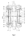
- the machine 1 shown on the Figures 1 to 3 comprises a casing 2 of which is secured a stator 3 comprising a magnetic stack of stator plates 4 and windings 5.
- the machine 1 also comprises a rotor 10 which has been shown separately in FIG. figure 6 .
- the rotor 10 comprises a shaft 11 of which are secured rotor plates 14, windings 13, and two fans 18 disposed on either side of these windings 13.
- the rotor 10 may comprise interpolar channels 110.
- the fans 18 rotate at the end flanges 20 of the machine, provided with openings 24 for the air outlet.
- These flanges 20 can support bearing assemblies traversed by the shaft 11 (not shown for the sake of clarity of the drawing).
- the fans 18 are designed to suck the air inside the machine and reject it through the outlets 24, and for this purpose have blades 30 which are attached to a hub 31 enabling them to be fixed on the tree 11.
- Each fan 18 may comprise, as seen in FIG. figure 2 , an annular lip 34 which closes a space 40 located between the housing 2 and the stator 3, and forces the air to bypass the coil heads 46 of the stator.
- Each fan 18 may also comprise, in the example considered, an annular web 45 which comes slightly in axial overlap of the heads of the coils 46 of the stator.
- At least one channel 50 is formed between the stack of stator laminations 4 and the casing 2, for the circulation of the cooling air from air intake openings 52 formed in the casing 2, for example substantially at mid-air. length of the machine, this circulation taking place under the effect of the depression created by the fans 18.
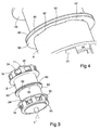
- the ears 52 can be made for example by machining the housing 2 and are delimited on the side of a transverse median plane of the machine by respective flanges 60, which protrude beyond the housing 2.
- the flanges 60 are for example integral with the pack of stator plates 4, being for example welded thereon.
- the flanges 60 may alternatively be made by a radial protrusion of a sheet superimposed on the stack of stator sheets.
- the flanges 60 may be parallel to each other and extend perpendicularly to the axis of rotation X.
- the pack of stator plates 4 comprises, as can be seen in particular in the figure 2 , passages 68 allowing the air entering through the inlet (s) 63 existing between the flanges 60 to gain the air gap 100 and the rotor 10.
- the fans 18 are rotated and air is sucked by both the inlet (s) 63 formed between the flanges and the flaps 52.
- the air sucked by the louvers 52 flows between the stack of stator plates 4 and the casing 2 to the space 40 in which the coil heads 46 are located, which it bypasses by being deflected by the sail 45, then is sucked by the fan channel located between the web 45 and the hub 31.
- the air sucked between the flanges 60 flows in the gap 100 and the interpolar channels 110 of the rotor.
- the stack of stator plates may comprise fins and / or channels, arranged or not in staggered rows, in order to increase the convective exchanges.
- the flanges may have particular shapes of "volute” type to allow to obtain better aeraulic performance of the assembly.
- the flanges can be arranged so that the outgoing air flow is oriented away from the central portion towards the ends.
- the collars 60 may be made with a shape different from that illustrated, in order to minimize possible recirculation of the air between the inputs and the outputs.
- Fans illustrated with dual channel fans can be substituted for separation of the stator and rotor cooling air flows.
Landscapes
- Engineering & Computer Science (AREA)
- Power Engineering (AREA)
- Motor Or Generator Cooling System (AREA)
Description
- La présente invention concerne les machines électriques tournantes et s'intéresse à leur refroidissement.
- La publication
JP 60257736 - La demande
DE 44 13 389 décrit une machine comportant deux ventilateurs. L'air est aspiré depuis au moins une entrée située dans la région médiane de la machine. Il en est de même du brevetGB 348 206 - L'invention concerne plus particulièrement mais non exclusivement le domaine des machines électriques de forte puissance, notamment des alternateurs de puissance supérieure ou égale à 100 kW. L'invention est aussi intéressante pour les machines de plus faible puissance électrique, car les pertes aéraulique induites par les ventilateurs sont plus faibles et donc le rendement de la machine est moins impacté par la mise en place d'un second ventilateur. L'invention a pour objet une machine électrique tournante selon la revendication 1 ainsi qu'un procédé de refroidissement d'une machine électrique tournante selon la revendication 10.
- Dans des exemples de mise en oeuvre de l'invention, un premier flux d'air circule entre un paquet de tôles du stator et le carter de la machine et un deuxième flux d'air circule dans l'entrefer de la machine, ces premier et deuxième flux d'air étant formés à partir d'entrées d'air respectives distinctes de la machine.
- En jouant sur la taille et forme de ces entrées d'air (ces deux caractéristiques pouvant, le cas échéant, être variables sur une même machine grâce par exemple à la mise en place d'un clapet coulissant permettant d'ouvrir ou fermer les entrées d'air), il est possible de maîtriser le refroidissement de la machine en fonction des caractéristiques de fonctionnement. On peut maîtriser le débit traversant le stator et celui traversant le rotor de façon indépendante. De plus, la séparation au niveau des entrées d'air permet d'éviter une recirculation entre le circuit rotor et le circuit stator, du fait de la perturbation des écoulements induite par la rotation du rotor. Ceci est une amélioration par rapport à la demande
JP 60257736 - Grâce à l'invention, la température moyenne du bobinage ainsi que celle des points chauds de la machine, généralement situés au centre dans une machine standard, sont diminuées, puisque de l'air frais peut circuler autour des parties centrales des bobinages stator et rotor.
- L'invention permet ainsi d'améliorer les échanges convectifs au sein des machines tournantes électriques ouvertes.
- Les ventilateurs peuvent être centrifuges, hélicocentrifuges ou autres.
- L'invention est particulièrement intéressante pour une machine électrique tournante à excitatrice intégrée. En effet, la présence de l'excitatrice en bout d'arbre peut nécessiter de percer le ventilateur afin de permettre la connexion électrique entre la roue polaire et l'induit de l'excitatrice. Dans le cas d'une excitatrice intégrée au bobinage principal, un tel perçage n'est plus nécessaire. Aussi, l'invention permet un meilleur refroidissement des machines, notamment des rotors, à excitatrices intégrées. Le passage d'air peut être relativement faible lorsque les rotors sont à pôles lisses, et les pertes de charges très élevées. Le débit traversant le rotor et permettant d'assurer un bon refroidissement est obtenu par la mise en place de deux ventilateurs montés en parallèle.
- Les entrées d'air peuvent être situées sensiblement à mi-distance des sorties d'air. Au moins une partie des entrées d'air peut être usinée dans le carter.
- L'air peut circuler dans au moins un canal ménagé entre le paquet de tôles du stator et le carter. Ce canal peut être formé au moins partiellement entre des ailettes du paquet de tôles, par exemple. La dimension radiale du canal est par exemple comprise entre 2 et 100 mm. L'air peut notamment circuler tout autour du paquet de tôles, sur 360° autour de l'axe de rotation du rotor.
- La machine comporte deux collerettes ménageant entre elles au moins une entrée d'air permettant à l'air extérieur d'être aspiré vers l'entrefer de la machine, par la dépression créée par les ventilateurs.
- Cela permet de minimiser le risque de recirculation d'air entre les entrées et les sorties de la machine.
- Les collerettes peuvent être solidaires du paquet de tôles statoriques. Le stator peut comporter au moins un passage à travers le paquet de tôles du stator, de façon à permettre à l'air de gagner l'entrefer de la machine et de circuler dans des canaux interpolaires du rotor, le cas échéant. L'espacement entre les collerettes est par exemple compris entre 2 et 150 mm.
- Le carter peut comporter au moins une ouverture permettant à l'air d'être aspiré dans le ou les canaux existant entre le paquet de tôles statoriques et le carter.
- Le carter peut notamment comporter une pluralité de telles ouvertures, qui peuvent être par exemple équiréparties angulairement.
- Les ouvertures sont par exemple formées par usinage du carter, et se présentent par exemple sous la forme d'une succession d'encoches fermées d'un côté par l'une des collerettes précitées.
- La section offerte au passage de l'air gagnant la machine entre les collerettes est par exemple comprise entre 20 et 90 %, mieux entre 60 et 80 % de la section totale des ouvertures définies par les encoches.
- Les ventilateurs peuvent être agencés pour amener l'air ayant circulé entre le paquet de tôles statoriques et le carter à rejoindre celui ayant circulé dans l'entrefer, avant de gagner les pales du ventilateur.
- Les deux ventilateurs peuvent être identiques ou différents, notamment lorsque les pales sont inclinées.
- Les ventilateurs peuvent comporter chacun une première lèvre fermant un espace situé entre le voile amont du ventilateur et le carter afin de former un «plan de joint», ce qui évite les recirculations du fluide de refroidissement.
- Chaque ventilateur peut comporter également une deuxième lèvre faisant saillie vers le ventilateur opposé et venant en recouvrement au moins partiel des têtes de bobines du stator.
- Les première et deuxième lèvres peuvent être annulaires et continues angulairement, chacune ayant par exemple un bord libre situé dans un plan perpendiculaire à l'axe de rotation du rotor.
- Le rotor peut être bobiné.
- Les premier et deuxième flux d'air sont formés à partir d'entrées d'air respectives distinctes de la machine.
- Le premier flux d'air peut être amené à contourner des têtes de bobines du stator avant de rejoindre le deuxième flux d'air. Le deuxième flux d'air peut encore rester indépendant du premier.
- L'invention pourra être mieux comprise à la lecture de la description détaillée qui va suivre, d'un exemple de mise en oeuvre non limitatif de celle-ci, et à l'examen du dessin annexé, sur lequel :
- la
figure 1 représente de manière schématique, de côté, une machine réalisée conformément à l'invention, - la
figure 2 est une coupe longitudinale, partielle et schématique, de la machine de lafigure 1 , - la
figure 3 représente la machine de lafigure 1 , en perspective, - la
figure 4 représente un détail de réalisation, - la
figure 5 représente de manière schématique la machine de lafigure 1 , après enlèvement du carter, et - la
figure 6 représente de manière schématique, en perspective, le rotor. - La machine 1 représentée sur les
figures 1 à 3 comporte un carter 2 duquel est solidaire un stator 3 comportant un paquet de tôles statoriques magnétiques 4 et des enroulements 5. - La machine 1 comporte également un rotor 10 qui a été représenté isolément à la
figure 6 . - Le rotor 10 comporte un arbre 11 duquel sont solidaires des tôles rotoriques 14, des enroulements 13, ainsi que deux ventilateurs 18 disposés de part et d'autre de ces enroulements 13.
- Le rotor 10 peut comporter des canaux interpolaires 110.
- Les ventilateurs 18 tournent au niveau de flasques d'extrémité 20 de la machine, pourvus d'ouvertures 24 pour la sortie de l'air. Ces flasques 20 peuvent supporter des ensembles de roulements traversés par l'arbre 11 (non représentés dans un souci de clarté du dessin).
- Dans l'exemple considéré, les ventilateurs 18 sont prévus pour aspirer l'air à l'intérieur de la machine et le rejeter par les sorties 24, et comportent à cet effet des pales 30 qui se rattachent à un moyeu 31 permettant leur fixation sur l'arbre 11.
- Chaque ventilateur 18 peut comporter, comme on le voit à la
figure 2 , une lèvre annulaire 34 qui ferme un espace 40 situé entre le carter 2 et le stator 3, et oblige l'air à contourner les têtes de bobines 46 du stator. - Chaque ventilateur 18 peut également comporter, dans l'exemple considéré, un voile annulaire 45 qui vient légèrement en recouvrement axial des têtes des bobines 46 du stator.
- Au moins un canal 50 est formé entre le paquet de tôles statoriques 4 et le carter 2, pour la circulation de l'air de refroidissement depuis des ouies d'entrée d'air 52 formées dans le carter 2, par exemple sensiblement à mi-longueur de la machine, cette circulation s'effectuant sous l'effet de la dépression créée par les ventilateurs 18.
- Les ouies 52 peuvent être réalisées par exemple par usinage du carter 2 et sont délimitées du côté d'un plan médian transversal de la machine par des collerettes respectives 60, lesquelles font saillie au-delà du carter 2.
- Les collerettes 60 sont par exemple solidaires du paquet de tôles statoriques 4, étant par exemple soudées sur celui-ci.
- Les collerettes 60 peuvent en variante être réalisées par une excroissance radiale d'une tôle se superposant au paquet de tôles statoriques.
- Les collerettes 60 peuvent être parallèles entre elles et s'étendre perpendiculairement à l'axe de rotation X.
- Le paquet de tôles statoriques 4 comporte, comme on peut le voir notamment à la
figure 2 , des passages 68 permettant à l'air entrant par la ou les entrées 63 existant entre les collerettes 60 de gagner l'entrefer 100 et le rotor 10. - En fonctionnement, les ventilateurs 18 sont entraînés en rotation et de l'air est aspiré à la fois par la ou les entrées 63 formées entre les collerettes et les ouies 52.
- L'air aspiré par les ouies 52 circule entre le paquet de tôles statoriques 4 et le carter 2 jusqu'à l'espace 40 dans lequel sont situées les têtes de bobines 46, qu'il contourne en étant dévié par le voile 45, puis est aspiré par le canal du ventilateur situé entre le voile 45 et le moyeu 31.
- L'air aspiré entre les collerettes 60 circule dans l'entrefer 100 et les canaux interpolaires 110 du rotor.
- L'air sort en étant orienté radialement et obliquement en éloignement du plan médian transversal de la machine.
- Bien entendu, l'invention n'est pas limitée à l'exemple de réalisation qui vient d'être décrit.
- On peut notamment réaliser autrement les entrées d'air, les sorties d'air ou les ventilateurs.
- Le paquet de tôles statoriques peut comporter des ailettes et/ou des canaux, disposées ou non en quinconce, afin d'accroître les échanges convectifs.
- Les flasques peuvent avoir des formes particulières de type « volute » pour permettre d'obtenir de meilleures performances aérauliques de l'ensemble. De plus, afin d'éviter les recirculations du fluide de refroidissement entre les entrées et les sorties, les flasques peuvent être agencés de telle sorte que le flux d'air sortant soit orienté à l'opposé de la partie centrale, vers les extrémités.
- Les collerettes 60 peuvent être réalisées avec une forme différente de celle illustrée, afin de minimiser une éventuelle recirculation de l'air entre les entrées et les sorties.
- On peut remplacer les ventilateurs illustrés par des ventilateurs à double canal, permettant la séparation des flux d'air de refroidissement stator et rotor.
- L'expression « comportant un » doit être comprise comme étant synonyme de « comportant au moins un », sauf si le contraire est spécifié.
Claims (13)
- Machine électrique tournante comportant un carter (2) logeant au moins partiellement un stator (3) et un rotor (10), ce carter comportant des entrées d'air et des sorties d'air, le rotor entraînant au moins deux ventilateurs (18) disposés de manière à créer une circulation d'air depuis les entrées d'air vers les sorties d'air, les ventilateurs (18) étant disposés de part et d'autre de la partie du rotor interagissant avec le stator, les sorties d'air (24) étant disposées de part et d'autre des entrées d'âir (52, 63), un premier flux d'air circulant entre un paquet de tôles du stator et le carter de la machine et un deuxième flux d'air circulant dans l'entrefer de la machine, les premier et deuxième flux d'air étant formés à partir d'entrées d'air respectives distinctes de la machine,
le stator comportant au moins un passage (68) à travers le paquet de tôles (4) du stator, ce ou ces passages (68) communiquant avec la ou les entrées d'air (63), de façon à permettre à l'air de gagner l'entrefer (100) de la machine,
l'air circulant dans l'entrefer (100) étant aspiré au travers d'au moins une entrée (63) formée entre deux collerettes (60). - Machine selon la revendication précédente, l'air circulant dans au moins un canal (50) ménagé entre le paquet de tôles (4) du stator et le carter.
- Machine selon la revendication 1, le rotor comportant des canaux interpolaires (110) entre lesquels l'air ayant gagné l'entrefer peut circuler.
- Machine selon l'une quelconque des revendications précédentes, les ventilateurs étant agencés pour amener l'air ayant circulé entre le paquet (4) de tôles statoriques et le carter (2) à rejoindre celui ayant circulé dans l'entrefer (100) avant de gagner les pales (30) des ventilateurs (18).
- Machine selon la revendication précédente, les ventilateurs comportant chacun une première lèvre (34) fermant un espace (40) situé entre le ventilateur et le carter.
- Machine selon l'une quelconque des revendications précédentes, chaque ventilateur comportant une lèvre (45) faisant saillie vers le ventilateur opposé et venant en recouvrement au moins partiel de têtes de bobines (46) du stator.
- Machine selon l'une quelconque des revendications précédentes, les entrées d'air (52, 63) étant situées sensiblement à mi-distance des sorties d'air.
- machine selon l'une quelconque des revendications précédentes, au moins une partie des entrées d'air (52) étant usinée dans le carter (2).
- Machine selon l'une quelconque des revendications précédentes, le rotor étant bobiné.
- Procédé de refroidissement d'une machine électrique telle que définie dans la revendication 1, dans lequel le refroidissement s'effectue en faisant circuler deux flux d'air entre les entrées d'air et les sorties d'air, le premier flux d'air circulant entre un paquet (4) de tôles du stator et le carter (2) de la machine et le deuxième flux d'air circulant à travers au moins un passage (68) du paquet de tôles du stator et dans l'entrefer (100) de la machine, les deux flux d'air circulant depuis une zone médiane de la machine vers ses extrémités, sous l'action des deux ventilateurs (18), les premier et deuxième flux d'air étant formés à partir d'entrées d'air respectives distinctes de la machine.
- Procédé selon là revendication précédente, les premier et deuxième flux d'air se rejoignant avant leur éjection de la machine.
- Procédé selon l'une des revendications 10 ou 11, le premier flux d'air étant amené à contourner des têtes de bobines du stator avant de rejoindre le deuxième flux d'air.
- Procédé selon l'une quelconque des revendications 10 à 12, le deuxième flux d'air restant indépendant du premier.
Applications Claiming Priority (2)
| Application Number | Priority Date | Filing Date | Title |
|---|---|---|---|
| FR0852642A FR2930381A1 (fr) | 2008-04-18 | 2008-04-18 | Machine electrique a double ventilation separee |
| PCT/FR2009/050712 WO2009138636A1 (fr) | 2008-04-18 | 2009-04-16 | Machine electrique a double ventilation separee |
Publications (2)
| Publication Number | Publication Date |
|---|---|
| EP2274816A1 EP2274816A1 (fr) | 2011-01-19 |
| EP2274816B1 true EP2274816B1 (fr) | 2013-10-30 |
Family
ID=40011151
Family Applications (1)
| Application Number | Title | Priority Date | Filing Date |
|---|---|---|---|
| EP09745955.6A Active EP2274816B1 (fr) | 2008-04-18 | 2009-04-16 | Machine electrique a double ventilation separee |
Country Status (5)
| Country | Link |
|---|---|
| EP (1) | EP2274816B1 (fr) |
| CN (1) | CN102007668B (fr) |
| ES (1) | ES2442719T3 (fr) |
| FR (1) | FR2930381A1 (fr) |
| WO (1) | WO2009138636A1 (fr) |
Cited By (1)
| Publication number | Priority date | Publication date | Assignee | Title |
|---|---|---|---|---|
| CN106160315A (zh) * | 2016-08-02 | 2016-11-23 | 天津飞旋科技研发有限公司 | 带两叶轮的磁悬浮电机纯风冷散热结构 |
Families Citing this family (11)
| Publication number | Priority date | Publication date | Assignee | Title |
|---|---|---|---|---|
| GB2507153B (en) * | 2012-08-24 | 2020-08-26 | Borgwarner Inc | Cooling stator windings of an electric machine |
| JP6009913B2 (ja) * | 2012-11-20 | 2016-10-19 | 株式会社東芝 | 電動機 |
| CN104868656A (zh) * | 2015-04-29 | 2015-08-26 | 宁波诺丁汉大学 | 永磁电机 |
| FR3038468B1 (fr) | 2015-07-02 | 2018-07-13 | Moteurs Leroy-Somer | Machine electrique tournante a turbine a depression augmentee |
| GB2558171A (en) * | 2016-03-18 | 2018-07-11 | Cummins Generator Technologies | Adaptor with improved airflow |
| CN106411011B (zh) * | 2016-12-02 | 2018-10-16 | 沈阳工业大学 | 水内冷电机转子 |
| US11473587B2 (en) | 2017-08-24 | 2022-10-18 | Ge Renewable (Switzerland) Gmbh | Fan |
| DE102018101640B4 (de) * | 2018-01-25 | 2020-11-26 | ATE Antriebstechnik und Entwicklungs GmbH & Co. KG | Elektrische Antriebsvorrichtung |
| GB201911175D0 (en) * | 2019-08-05 | 2019-09-18 | Cummins Generator Technologies | Fan for a rotating electrical machine |
| WO2022244067A1 (fr) * | 2021-05-17 | 2022-11-24 | 三菱電機株式会社 | Machine électrique rotative |
| DE102021211919A1 (de) * | 2021-10-22 | 2023-04-27 | Zf Friedrichshafen Ag | Stator für eine elektrische Maschine |
Family Cites Families (9)
| Publication number | Priority date | Publication date | Assignee | Title |
|---|---|---|---|---|
| US1479636A (en) * | 1919-09-15 | 1924-01-01 | John B Wiard | Dynamo-electric machine |
| GB348206A (en) * | 1930-02-14 | 1931-05-14 | Gustaf Adolf Juhlin | Improvements in dynamo-electric machines |
| AT294967B (de) * | 1967-10-20 | 1971-12-10 | Zaklady K Doswiadczalne Przemy | Kühlanordnung mit mehreren Strömungswegen für elektrische Maschinen |
| JPS60257736A (ja) * | 1984-05-31 | 1985-12-19 | Mitsubishi Electric Corp | 回転電機の通風冷却装置 |
| JPS6166543A (ja) * | 1984-09-07 | 1986-04-05 | Mitsubishi Electric Corp | 回転電機の通風冷却装置 |
| DE4413389A1 (de) * | 1993-04-20 | 1994-12-01 | Elektra Faurndau Elektro Masch | Elektrische Maschine |
| DE4412289A1 (de) * | 1993-04-22 | 1994-10-27 | Wanzl Entwicklung Gmbh | Einrichtung zum Ausleihen von Transportwagen |
| DE19943444A1 (de) * | 1999-09-11 | 2001-03-15 | Heinz Dieter Eberhardt | Kühlsystem für rotierende elektrische Maschinen |
| JP5026010B2 (ja) * | 2006-07-19 | 2012-09-12 | デンヨー株式会社 | 回転機器の冷却ファン |
-
2008
- 2008-04-18 FR FR0852642A patent/FR2930381A1/fr not_active Withdrawn
-
2009
- 2009-04-16 WO PCT/FR2009/050712 patent/WO2009138636A1/fr not_active Ceased
- 2009-04-16 EP EP09745955.6A patent/EP2274816B1/fr active Active
- 2009-04-16 ES ES09745955.6T patent/ES2442719T3/es active Active
- 2009-04-16 CN CN200980113513.0A patent/CN102007668B/zh not_active Expired - Fee Related
Cited By (1)
| Publication number | Priority date | Publication date | Assignee | Title |
|---|---|---|---|---|
| CN106160315A (zh) * | 2016-08-02 | 2016-11-23 | 天津飞旋科技研发有限公司 | 带两叶轮的磁悬浮电机纯风冷散热结构 |
Also Published As
| Publication number | Publication date |
|---|---|
| WO2009138636A1 (fr) | 2009-11-19 |
| FR2930381A1 (fr) | 2009-10-23 |
| CN102007668A (zh) | 2011-04-06 |
| ES2442719T3 (es) | 2014-02-13 |
| CN102007668B (zh) | 2014-01-22 |
| EP2274816A1 (fr) | 2011-01-19 |
Similar Documents
| Publication | Publication Date | Title |
|---|---|---|
| EP2311172B1 (fr) | Machine electrique tournante | |
| EP2274816A1 (fr) | Machine electrique a double ventilation separee | |
| EP2266191B1 (fr) | Machine electrique comportant un ventilateur a canaux multiples | |
| EP1351371B1 (fr) | Machine électrique tournante à ventilation forcée | |
| EP4059122A1 (fr) | Machine a refroidissement par liquide | |
| EP2826133B1 (fr) | Ensemble de flasques comportant des pales axiales generant un flux d'air axial a travers d'un rotor | |
| EP1293026B1 (fr) | Ventilateur pour machine electrique tournante | |
| FR2865080A1 (fr) | Ralentisseur electromagnetique radial simple comportant des moyens pour assurer une ventilation | |
| WO2017001671A1 (fr) | Machine electrique tournante a turbine a depression augmentee | |
| EP2826135B1 (fr) | Ensemble de flasques de rotor de machine electrique tournante comportant des orifices asymetriques favorisant un flux d'air axial a l'interieur du rotor et rotor de machine electrique tournante associe | |
| WO2022112704A1 (fr) | Flasque et rotor de machine électrique tournante | |
| WO2013093257A1 (fr) | Rotor a poles saillants comportant un dispositif d'isolation de bobinages et dispositif d'isolation de bobinages associe | |
| EP2764606A2 (fr) | Rotor comportant des regions interpolaires a canaux de refroidissement | |
| FR3116963A1 (fr) | Flasque et rotor de machine électrique tournante | |
| EP2826132B1 (fr) | Ensemble de flasques munis de pions de centrage et de conducteur de chaleur favorisant le refroidissement | |
| WO2017134372A1 (fr) | Machine electrique tournante munie d'ailettes de refroidissement | |
| WO2023062307A1 (fr) | Flasque pour machine électrique tournante | |
| FR3062531B1 (fr) | Machine electrique tournante munie d'un obturateur limitant un rebouclage d'air chaud | |
| WO2017134375A1 (fr) | Machine electrique tournante munie d'au moins une ouverture d'aeration dans un dissipateur de chaleur | |
| FR3116962A1 (fr) | Flasque et rotor de machine électrique tournante | |
| FR3083021A1 (fr) | Machine electrique comprenant un conduit de refroidissement ayant un orifice de sortie situe dans une dent | |
| FR2811158A1 (fr) | Ventilateur a ailettes pour machine electrique tournante, notamment pour alternateur de vehicule automobile | |
| FR2811157A1 (fr) | Ventilateur a pales de hauteur decroissante pour machine electrique tournante, notamment pour alternateur de vehicule automobile | |
| FR3124334A1 (fr) | Séparateur de phase pour stator de machine électrique tournante | |
| FR3153479A1 (fr) | Machine électrique à flux axial avec canal de refroidissement traversant l’arbre de rotor |
Legal Events
| Date | Code | Title | Description |
|---|---|---|---|
| PUAI | Public reference made under article 153(3) epc to a published international application that has entered the european phase |
Free format text: ORIGINAL CODE: 0009012 |
|
| 17P | Request for examination filed |
Effective date: 20101103 |
|
| AK | Designated contracting states |
Kind code of ref document: A1 Designated state(s): AT BE BG CH CY CZ DE DK EE ES FI FR GB GR HR HU IE IS IT LI LT LU LV MC MK MT NL NO PL PT RO SE SI SK TR |
|
| AX | Request for extension of the european patent |
Extension state: AL BA RS |
|
| 17Q | First examination report despatched |
Effective date: 20110520 |
|
| DAX | Request for extension of the european patent (deleted) | ||
| GRAP | Despatch of communication of intention to grant a patent |
Free format text: ORIGINAL CODE: EPIDOSNIGR1 |
|
| INTG | Intention to grant announced |
Effective date: 20130627 |
|
| GRAS | Grant fee paid |
Free format text: ORIGINAL CODE: EPIDOSNIGR3 |
|
| GRAA | (expected) grant |
Free format text: ORIGINAL CODE: 0009210 |
|
| AK | Designated contracting states |
Kind code of ref document: B1 Designated state(s): AT BE BG CH CY CZ DE DK EE ES FI FR GB GR HR HU IE IS IT LI LT LU LV MC MK MT NL NO PL PT RO SE SI SK TR |
|
| REG | Reference to a national code |
Ref country code: GB Ref legal event code: FG4D Free format text: NOT ENGLISH |
|
| REG | Reference to a national code |
Ref country code: CH Ref legal event code: EP |
|
| REG | Reference to a national code |
Ref country code: AT Ref legal event code: REF Ref document number: 638723 Country of ref document: AT Kind code of ref document: T Effective date: 20131115 |
|
| REG | Reference to a national code |
Ref country code: IE Ref legal event code: FG4D Free format text: LANGUAGE OF EP DOCUMENT: FRENCH |
|
| REG | Reference to a national code |
Ref country code: DE Ref legal event code: R096 Ref document number: 602009019767 Country of ref document: DE Effective date: 20131224 |
|
| REG | Reference to a national code |
Ref country code: SE Ref legal event code: TRGR |
|
| REG | Reference to a national code |
Ref country code: ES Ref legal event code: FG2A Ref document number: 2442719 Country of ref document: ES Kind code of ref document: T3 Effective date: 20140213 |
|
| REG | Reference to a national code |
Ref country code: NL Ref legal event code: VDEP Effective date: 20131030 |
|
| REG | Reference to a national code |
Ref country code: AT Ref legal event code: MK05 Ref document number: 638723 Country of ref document: AT Kind code of ref document: T Effective date: 20131030 |
|
| REG | Reference to a national code |
Ref country code: LT Ref legal event code: MG4D |
|
| PG25 | Lapsed in a contracting state [announced via postgrant information from national office to epo] |
Ref country code: FI Free format text: LAPSE BECAUSE OF FAILURE TO SUBMIT A TRANSLATION OF THE DESCRIPTION OR TO PAY THE FEE WITHIN THE PRESCRIBED TIME-LIMIT Effective date: 20131030 Ref country code: IS Free format text: LAPSE BECAUSE OF FAILURE TO SUBMIT A TRANSLATION OF THE DESCRIPTION OR TO PAY THE FEE WITHIN THE PRESCRIBED TIME-LIMIT Effective date: 20140228 Ref country code: LT Free format text: LAPSE BECAUSE OF FAILURE TO SUBMIT A TRANSLATION OF THE DESCRIPTION OR TO PAY THE FEE WITHIN THE PRESCRIBED TIME-LIMIT Effective date: 20131030 Ref country code: NO Free format text: LAPSE BECAUSE OF FAILURE TO SUBMIT A TRANSLATION OF THE DESCRIPTION OR TO PAY THE FEE WITHIN THE PRESCRIBED TIME-LIMIT Effective date: 20140130 Ref country code: HR Free format text: LAPSE BECAUSE OF FAILURE TO SUBMIT A TRANSLATION OF THE DESCRIPTION OR TO PAY THE FEE WITHIN THE PRESCRIBED TIME-LIMIT Effective date: 20131030 Ref country code: NL Free format text: LAPSE BECAUSE OF FAILURE TO SUBMIT A TRANSLATION OF THE DESCRIPTION OR TO PAY THE FEE WITHIN THE PRESCRIBED TIME-LIMIT Effective date: 20131030 |
|
| PG25 | Lapsed in a contracting state [announced via postgrant information from national office to epo] |
Ref country code: AT Free format text: LAPSE BECAUSE OF FAILURE TO SUBMIT A TRANSLATION OF THE DESCRIPTION OR TO PAY THE FEE WITHIN THE PRESCRIBED TIME-LIMIT Effective date: 20131030 Ref country code: LV Free format text: LAPSE BECAUSE OF FAILURE TO SUBMIT A TRANSLATION OF THE DESCRIPTION OR TO PAY THE FEE WITHIN THE PRESCRIBED TIME-LIMIT Effective date: 20131030 Ref country code: CY Free format text: LAPSE BECAUSE OF FAILURE TO SUBMIT A TRANSLATION OF THE DESCRIPTION OR TO PAY THE FEE WITHIN THE PRESCRIBED TIME-LIMIT Effective date: 20131030 |
|
| PG25 | Lapsed in a contracting state [announced via postgrant information from national office to epo] |
Ref country code: PT Free format text: LAPSE BECAUSE OF FAILURE TO SUBMIT A TRANSLATION OF THE DESCRIPTION OR TO PAY THE FEE WITHIN THE PRESCRIBED TIME-LIMIT Effective date: 20140228 |
|
| PG25 | Lapsed in a contracting state [announced via postgrant information from national office to epo] |
Ref country code: EE Free format text: LAPSE BECAUSE OF FAILURE TO SUBMIT A TRANSLATION OF THE DESCRIPTION OR TO PAY THE FEE WITHIN THE PRESCRIBED TIME-LIMIT Effective date: 20131030 |
|
| REG | Reference to a national code |
Ref country code: DE Ref legal event code: R097 Ref document number: 602009019767 Country of ref document: DE |
|
| PG25 | Lapsed in a contracting state [announced via postgrant information from national office to epo] |
Ref country code: SK Free format text: LAPSE BECAUSE OF FAILURE TO SUBMIT A TRANSLATION OF THE DESCRIPTION OR TO PAY THE FEE WITHIN THE PRESCRIBED TIME-LIMIT Effective date: 20131030 Ref country code: PL Free format text: LAPSE BECAUSE OF FAILURE TO SUBMIT A TRANSLATION OF THE DESCRIPTION OR TO PAY THE FEE WITHIN THE PRESCRIBED TIME-LIMIT Effective date: 20131030 Ref country code: RO Free format text: LAPSE BECAUSE OF FAILURE TO SUBMIT A TRANSLATION OF THE DESCRIPTION OR TO PAY THE FEE WITHIN THE PRESCRIBED TIME-LIMIT Effective date: 20131030 |
|
| PLBE | No opposition filed within time limit |
Free format text: ORIGINAL CODE: 0009261 |
|
| STAA | Information on the status of an ep patent application or granted ep patent |
Free format text: STATUS: NO OPPOSITION FILED WITHIN TIME LIMIT |
|
| PG25 | Lapsed in a contracting state [announced via postgrant information from national office to epo] |
Ref country code: DK Free format text: LAPSE BECAUSE OF FAILURE TO SUBMIT A TRANSLATION OF THE DESCRIPTION OR TO PAY THE FEE WITHIN THE PRESCRIBED TIME-LIMIT Effective date: 20131030 |
|
| 26N | No opposition filed |
Effective date: 20140731 |
|
| REG | Reference to a national code |
Ref country code: DE Ref legal event code: R097 Ref document number: 602009019767 Country of ref document: DE Effective date: 20140731 |
|
| PG25 | Lapsed in a contracting state [announced via postgrant information from national office to epo] |
Ref country code: MC Free format text: LAPSE BECAUSE OF FAILURE TO SUBMIT A TRANSLATION OF THE DESCRIPTION OR TO PAY THE FEE WITHIN THE PRESCRIBED TIME-LIMIT Effective date: 20131030 Ref country code: LU Free format text: LAPSE BECAUSE OF FAILURE TO SUBMIT A TRANSLATION OF THE DESCRIPTION OR TO PAY THE FEE WITHIN THE PRESCRIBED TIME-LIMIT Effective date: 20140416 |
|
| REG | Reference to a national code |
Ref country code: CH Ref legal event code: PL |
|
| REG | Reference to a national code |
Ref country code: SE Ref legal event code: EUG |
|
| REG | Reference to a national code |
Ref country code: IE Ref legal event code: MM4A |
|
| PG25 | Lapsed in a contracting state [announced via postgrant information from national office to epo] |
Ref country code: SE Free format text: LAPSE BECAUSE OF NON-PAYMENT OF DUE FEES Effective date: 20140417 Ref country code: CH Free format text: LAPSE BECAUSE OF NON-PAYMENT OF DUE FEES Effective date: 20140430 Ref country code: LI Free format text: LAPSE BECAUSE OF NON-PAYMENT OF DUE FEES Effective date: 20140430 Ref country code: CZ Free format text: LAPSE BECAUSE OF NON-PAYMENT OF DUE FEES Effective date: 20140416 |
|
| PG25 | Lapsed in a contracting state [announced via postgrant information from national office to epo] |
Ref country code: SI Free format text: LAPSE BECAUSE OF FAILURE TO SUBMIT A TRANSLATION OF THE DESCRIPTION OR TO PAY THE FEE WITHIN THE PRESCRIBED TIME-LIMIT Effective date: 20131030 |
|
| PG25 | Lapsed in a contracting state [announced via postgrant information from national office to epo] |
Ref country code: IE Free format text: LAPSE BECAUSE OF NON-PAYMENT OF DUE FEES Effective date: 20140416 |
|
| REG | Reference to a national code |
Ref country code: ES Ref legal event code: FD2A Effective date: 20160105 |
|
| PG25 | Lapsed in a contracting state [announced via postgrant information from national office to epo] |
Ref country code: ES Free format text: LAPSE BECAUSE OF NON-PAYMENT OF DUE FEES Effective date: 20140417 |
|
| REG | Reference to a national code |
Ref country code: FR Ref legal event code: PLFP Year of fee payment: 8 |
|
| PG25 | Lapsed in a contracting state [announced via postgrant information from national office to epo] |
Ref country code: MT Free format text: LAPSE BECAUSE OF FAILURE TO SUBMIT A TRANSLATION OF THE DESCRIPTION OR TO PAY THE FEE WITHIN THE PRESCRIBED TIME-LIMIT Effective date: 20131030 |
|
| PG25 | Lapsed in a contracting state [announced via postgrant information from national office to epo] |
Ref country code: BG Free format text: LAPSE BECAUSE OF FAILURE TO SUBMIT A TRANSLATION OF THE DESCRIPTION OR TO PAY THE FEE WITHIN THE PRESCRIBED TIME-LIMIT Effective date: 20131030 Ref country code: GR Free format text: LAPSE BECAUSE OF FAILURE TO SUBMIT A TRANSLATION OF THE DESCRIPTION OR TO PAY THE FEE WITHIN THE PRESCRIBED TIME-LIMIT Effective date: 20140131 |
|
| PG25 | Lapsed in a contracting state [announced via postgrant information from national office to epo] |
Ref country code: TR Free format text: LAPSE BECAUSE OF FAILURE TO SUBMIT A TRANSLATION OF THE DESCRIPTION OR TO PAY THE FEE WITHIN THE PRESCRIBED TIME-LIMIT Effective date: 20131030 Ref country code: BE Free format text: LAPSE BECAUSE OF FAILURE TO SUBMIT A TRANSLATION OF THE DESCRIPTION OR TO PAY THE FEE WITHIN THE PRESCRIBED TIME-LIMIT Effective date: 20140430 Ref country code: HU Free format text: LAPSE BECAUSE OF FAILURE TO SUBMIT A TRANSLATION OF THE DESCRIPTION OR TO PAY THE FEE WITHIN THE PRESCRIBED TIME-LIMIT; INVALID AB INITIO Effective date: 20090416 |
|
| REG | Reference to a national code |
Ref country code: FR Ref legal event code: PLFP Year of fee payment: 9 |
|
| REG | Reference to a national code |
Ref country code: FR Ref legal event code: PLFP Year of fee payment: 10 |
|
| PG25 | Lapsed in a contracting state [announced via postgrant information from national office to epo] |
Ref country code: MK Free format text: LAPSE BECAUSE OF FAILURE TO SUBMIT A TRANSLATION OF THE DESCRIPTION OR TO PAY THE FEE WITHIN THE PRESCRIBED TIME-LIMIT Effective date: 20131030 |
|
| PGFP | Annual fee paid to national office [announced via postgrant information from national office to epo] |
Ref country code: IT Payment date: 20190412 Year of fee payment: 11 Ref country code: DE Payment date: 20190607 Year of fee payment: 11 |
|
| PGFP | Annual fee paid to national office [announced via postgrant information from national office to epo] |
Ref country code: GB Payment date: 20190424 Year of fee payment: 11 |
|
| REG | Reference to a national code |
Ref country code: DE Ref legal event code: R119 Ref document number: 602009019767 Country of ref document: DE |
|
| PG25 | Lapsed in a contracting state [announced via postgrant information from national office to epo] |
Ref country code: DE Free format text: LAPSE BECAUSE OF NON-PAYMENT OF DUE FEES Effective date: 20201103 |
|
| GBPC | Gb: european patent ceased through non-payment of renewal fee |
Effective date: 20200416 |
|
| PG25 | Lapsed in a contracting state [announced via postgrant information from national office to epo] |
Ref country code: GB Free format text: LAPSE BECAUSE OF NON-PAYMENT OF DUE FEES Effective date: 20200416 |
|
| PG25 | Lapsed in a contracting state [announced via postgrant information from national office to epo] |
Ref country code: IT Free format text: LAPSE BECAUSE OF NON-PAYMENT OF DUE FEES Effective date: 20200416 |
|
| PGFP | Annual fee paid to national office [announced via postgrant information from national office to epo] |
Ref country code: FR Payment date: 20260420 Year of fee payment: 18 |