EP2275345B1 - Système de couchette - Google Patents
Système de couchette Download PDFInfo
- Publication number
- EP2275345B1 EP2275345B1 EP10150908.1A EP10150908A EP2275345B1 EP 2275345 B1 EP2275345 B1 EP 2275345B1 EP 10150908 A EP10150908 A EP 10150908A EP 2275345 B1 EP2275345 B1 EP 2275345B1
- Authority
- EP
- European Patent Office
- Prior art keywords
- seat
- platform
- platform portion
- berth sleeper
- sleeper system
- Prior art date
- Legal status (The legal status is an assumption and is not a legal conclusion. Google has not performed a legal analysis and makes no representation as to the accuracy of the status listed.)
- Active
Links
Images


Classifications
-
- B—PERFORMING OPERATIONS; TRANSPORTING
- B64—AIRCRAFT; AVIATION; COSMONAUTICS
- B64D—EQUIPMENT FOR FITTING IN OR TO AIRCRAFT; FLIGHT SUITS; PARACHUTES; ARRANGEMENT OR MOUNTING OF POWER PLANTS OR PROPULSION TRANSMISSIONS IN AIRCRAFT
- B64D11/00—Passenger or crew accommodation; Flight-deck installations not otherwise provided for
- B64D11/06—Arrangements of seats, or adaptations or details specially adapted for aircraft seats
-
- B—PERFORMING OPERATIONS; TRANSPORTING
- B64—AIRCRAFT; AVIATION; COSMONAUTICS
- B64D—EQUIPMENT FOR FITTING IN OR TO AIRCRAFT; FLIGHT SUITS; PARACHUTES; ARRANGEMENT OR MOUNTING OF POWER PLANTS OR PROPULSION TRANSMISSIONS IN AIRCRAFT
- B64D11/00—Passenger or crew accommodation; Flight-deck installations not otherwise provided for
- B64D11/06—Arrangements of seats, or adaptations or details specially adapted for aircraft seats
- B64D11/0602—Seat modules, i.e. seat systems including furniture separate from the seat itself
- B64D11/0604—Seat modules, i.e. seat systems including furniture separate from the seat itself including a bed, e.g. cocoon type passenger seat modules
Definitions
- the present patent application relates to berth sleeper systems and, more particularly, to berth sleeper systems for aircraft and the like that are convertible from an upright, sitting configuration to a horizontal, sleeping configuration.
- the seats, as well as the arrangement of seats, on a typical aircraft are configured to provide passengers with a certain amount of personal space while maximizing the total number of passengers that may be accommodated by the overall useable space in the aircraft. Therefore, the seats on a typical commercial aircraft are often closely grouped together and substantially only partially recline.
- WO2008/046027 discloses a translatable and rotatable passenger seat.
- the seat includes a seat bottom and a seat back operably coupled to the seat bottom.
- the passenger seat is translatable fore-and-aft and side-to-side in a horizontal directions, and is rotatable about a vertical axis so as to be oriented in any desired horizontal direction.
- the passenger seat is movable between an upright seating position and a reclined sleeping position.
- a passenger seating arrangement consists of a plurality of passenger seats arranged in a column with adjacent passenger seats separated by a privacy divider.
- a tray table carried by the privacy divider is mounted so as to be selectively raised and lowered and to be rotatable about a horizontal axis. When in the reclined sleeping position, the tray table may be lowered such that the tray is aligned with the horizontal plane of the seat back.
- the disclosed berth sleeper system includes a platform portion and a seat portion, the seat portion defining an axis of rotation and being rotateable relative to the platform portion about the axis of rotation, wherein the seat portion includes a seat base, a backrest and a recline mechanism, the recline mechanism supporting the seat base and the backrest in an upright configuration and a horizontal configuration, wherein the seat base is co-planar with the platform portion, while the backrest is disposed at an angle relative to the seat base in the upright configuration, and wherein the seat base and the backrest are co-planar with the platform portion in the horizontal configuration.
- the disclosed berth sleeper system may include a substantially flat platform portion and a seat portion positioned adjacent to the platform portion, the seat portion defining an axis of rotation and being rotateable at least about 45 degrees relative to the platform portion about the axis of rotation, wherein the seat portion includes a seat base, a backrest and a recline mechanism, the recline mechanism supporting the seat base and the backrest in an upright configuration and a horizontal configuration, wherein the seat base is co-planar with the platform portion and the backrest is disposed at an angle relative to the seat base in the upright configuration, and wherein the seat base, the backrest and the platform portion define a co-planar and continuous sleeping platform in the horizontal configuration.
- one aspect of the disclosed berth sleeper system may include a seat portion 12 and a platform portion 14.
- the seat portion 12 may rotate relative to the platform portion 14 about an axis A 1 of rotation, which may be an axis parallel with the z-axis ( Fig. 2 ), and may recline from an upright, sitting configuration ( Figs. 1-3 ) to a horizontal, sleeping configuration ( Fig. 4 ) to form a sleeping platform.
- the disclosed berth sleeper system 10 may be positioned in a personal sleeping compartment 16 defined by a wall 18.
- the personal sleeping compartment 16 may be in an aircraft (e.g., a commercial airplane), a train, a ship or an automobile.
- aircraft e.g., a commercial airplane
- train e.g., a train
- ship e.g., a ship
- automobile e.g., a passenger car
- the disclosed berth sleeper system 10 may be used in a variety of applications.
- the platform portion 14 of the disclosed berth sleeper system 10 may be a substantially planer platform, wherein the plane defined by the platform portion 14 may be substantially parallel with the x-y plane ( Fig. 2 ).
- the platform portion 14 may be a substantially flat and horizontal platform.
- the platform portion 14 may be cushioned (e.g., with foam padding and/or springs) and upholstered for comfort, as is well known in the art.
- the platform portion 14 may be positioned relative to the seat portion 12 such that the platform portion 14 is co-planar with the seat base 20 (discussed below) of the seat portion 12.
- the platform portion 14 may be elevated about 20 inches from the sub-structure.
- Exemplary techniques for elevating the platform portion 14 relative to the sub-structure include the use of a support structure (not shown) to raise the platform portion 14 and connecting the platform portion 14 to the wall 18 of the personal sleeping compartment 16.
- the platform portion 14 may have various shapes in top view to accommodate the shape of the personal sleeping compartment 16. Furthermore, the platform portion 14 may be sufficiently elongated along a platform axis A 2 to accommodate a substantial portion of a prone human. For example, the platform portion 14 may have a length (in the direction parallel with the platform axis A 2 ) of about 3 to about 5 feet, about 90cm to about 150cm.
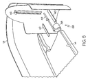
- the seat portion 12 of the berth sleeper system 10 includes a seat base 20, a backrest 22, a support structure 24 and a recline mechanism 26 ( Fig. 5 ).
- the seat portion 12 may additionally include a headrest 28.
- the seat portion 12 may additionally include armrests 30, 32.
- the seat portion 12 may additionally include both the headrest 28 and the armrests 30, 32.
- the seat base 20 and the backrest 22 of the seat portion 12, as well as the optional headrest 28 and the armrests 30, 32 may be cushioned (e.g., with foam padding and/or springs) and upholstered for comfort, as is well known in the art.
- the support structure 24 may be secured to a sub-structure, such as a floor or the ground, and may rotateably support the seat portion 12 relative to the sub-structure such that the seat portion 12 is rotateable relative to the platform portion 14 about the axis A 1 of rotation.
- the seat portion 12 may rotate about 45 degrees relative to the platform portion 14.
- Fig. 4 shows the seat portion 12 aligned with the platform portion 14 (i.e., zero degrees of rotation) and Fig. 1 shows the seat portion 12 rotated about 45 degrees from the platform portion 14.
- the seat portion 12 may rotate 360 degrees about the axis A 1 of rotation.
- the support structure 24 may include a base 34 secured to the sub-structure and a mount 36 to which the seat base 20 and the backrest 22 may be secured.
- the mount 36 may be rotateably connected to the base 34 to define a swivel connection therebetween.
- Roller bearings (not shown) or the like may be provided to facilitate low-friction rotation of the mount 36 (and associated components of the scat portion 12) relative to the base 34.
- the recline mechanism 26 may be any mechanism that facilitates movement of the seat base 20 and the backrest 22 from the upright, sitting configuration shown in Figs. 1-3 to the horizontal, sleeping configuration shown in Fig. 4 .
- the recline mechanism 26 may be a mechanical mechanism, an electromechanical mechanism or the like.
- the seat base 20 of the seat portion 12 is co-planar with the platform portion 14, while the backrest 22 of the seat portion 12 may be disposed at an angle (e.g., about 10 to about 90 degrees) relative to the seat base 20.
- a minimum spacing may be provided between the distal portion 52 of the seat base 20 and the proximal portion 54 of the platform portion 14 to provide legroom therebetween.
- a minimum spacing of about 8 to about 14 inches, about 20 to about 36 cm may be provided between the distal portion 52 of the seat base 20 and the proximal portion 54 of the platform portion 14 when the seat portion 12 is in the upright, sitting configuration.
- both the seat base 20 and the backrest 22 of the seat portion 12 is co-planar with the platform portion 14. Furthermore, in the horizontal, sleeping configuration, the spacing between the distal portion 52 of the seat base 20 and the proximal portion 54 of the platform portion 14 may be minimized (e.g., at most about 2 inches, about 5cm), thereby providing a substantially continuous sleeping platform comprised of both the platform portion 14 and the seat portion 12.
- a co-planar sleeping platform is desired to improve comfort and, therefore, two planes displaced by up to about 3 inches may still be regarded as " co-planar.”
- the recline mechanism 26 may include an electric motor 38, two drawer slides 40, 42, a linear drive 44 and a roller track 46.
- the top portion 48 ( Fig. 1 ) of the backrest 22 may be moveably connected to the roller track 46 such that the backrest 22 can recline from the upright configuration to the fully reclined configuration by traveling along the roller track 46.
- the seat base for example the rear portion 50 ( Fig. 1 ) of the seat base 20, may be connected to the linear drive 44 such that the linear drive 44 may urge the seat base 20 in the proximal and distal directions (i.e., along axis A 2 ).
- the seat base 20 may be secured to and supported by the drawer slides 40, 42.
- the linear drive 44 may urge the seat base 20 in the distal direction (e.g., along axis A 2 toward the proximal end 54 of the platform portion 14). While the seat base 20 is distally advancing, the backrest 22, which may be hingedly connected to the seat base 20 or independent of the seat base 20, may travel along the roller track 46 until the backrest 22 is substantially co-planar with the seat base 20 and the platform portion 14. Of course, the process may be reversed by reversing the direction of travel of the linear drive 44, thereby returning the seat portion 12 to the upright, sitting configuration.
- the disclosed berth sleeper system 10 may include a seat portion 12 that rotates relative to a platform portion 14 about an axis A 1 of rotation, wherein the seat portion 12 is reclineable such that the seat base 20 and the backrest 22 of the seat portion 12 are aligned and co-planar with the platform portion 14 to form a substantially continuous sleeping platform.
Landscapes
- Engineering & Computer Science (AREA)
- Aviation & Aerospace Engineering (AREA)
- Seats For Vehicles (AREA)
- Chairs For Special Purposes, Such As Reclining Chairs (AREA)
Claims (15)
- Système de couchette (10) comprenant :une partie de plateforme (14) ; etune partie de siège (12), ladite partie de siège définissant un axe de rotation et étant rotative par rapport à ladite partie de plateforme autour dudit axe de rotation, dans lequel ladite partie de siège inclut une base de siège (20), un dossier (22) et un mécanisme d'inclinaison (26), ledit mécanisme d'inclinaison supportant ladite base de siège et ledit dossier dans une configuration verticale et une configuration horizontale,dans lequel ladite base de siège est coplanaire avec ladite partie de plateforme, alors que ledit dossier est disposé à un angle par rapport à ladite base de siège dans ladite configuration verticale, et dans lequel ladite base de siège et ledit dossier sont coplanaires avec ladite partie de plateforme dans ladite configuration horizontale.
- Système de couchette (10) selon la revendication 1, comprenant en outre une paroi (18) définissant un compartiment de couchette individuelle (16), dans lequel ladite partie de plateforme et ladite partie de siège sont positionnées dans ledit compartiment de couchette individuelle.
- Système de couchette (10) selon la revendication 1, dans lequel ladite partie de plateforme comprend l'amortissement.
- Système de couchette (10) selon la revendication 1, dans lequel ladite partie de plateforme présente une longueur d'environ 3 à 5 pieds, d'environ 90 à 150 cm.
- Système de couchette (10) selon la revendication 1, dans lequel ladite partie de siège comprend en outre un repose-tête (28).
- Système de couchette (10) selon la revendication 1, dans lequel ladite partie de siège comprend en outre au moins un accoudoir (30, 52).
- Système de couchette (10) selon la revendication 1, dans lequel ladite partie de siège (12) est rotative de 45 degrés par rapport à ladite partie de plateforme (14).
- Système de couchette (10) selon la revendication 1, dans lequel ledit mécanisme d'inclinaison (26) comprend un entraînement linéaire (44) relié à ladite base de siège (20).
- Système de couchette (10) selon la revendication 8, dans lequel ledit mécanisme d'inclinaison (26) comprend en outre un moteur électrique (38) couplé audit entraînement linéaire (44).
- Système de couchette (10) selon la revendication 1, dans lequel ledit mécanisme d'inclinaison (26) comprend un chemin de roulement (46) et ledit dossier (22) est relié de manière mobile audit chemin de roulement.
- Système de couchette (10) selon la revendication 1, dans lequel ladite base de siège (20), ledit dossier (22) et ladite partie de plateforme (14) définissent une plateforme de couchette sensiblement continue lorsque ladite partie de siège (12) est dans ladite configuration horizontale.
- Système de couchette (10) selon la revendication 1, dans lequel :ladite partie de plateforme (14) est sensiblement plate ;ladite partie de siège (12) est positionnée à côté de ladite partie de plateforme ; et ladite partie de siège est rotative au moins de 45 degrés par rapport à ladite partie de plateforme autour dudit axe de rotation.
- Système de couchette (10) selon la revendication 1 ou 12, dans lequel ladite partie de siège (12) comprend en outre une structure porteuse qui élève ladite base de siège (20) d'une sous-structure associée, dans lequel ladite structure porteuse définit une liaison pivotante avec ladite sous-structure.
- Système de couchette (10) selon la revendication 1 ou 12, dans lequel ladite base de siège (20) comprend une extrémité distale (52) et ladite partie de plateforme (14) comprend une extrémité proximale (54) et dans lequel une distance entre ladite extrémité distale et ladite extrémité proximale est comprise entre environ 8 et 14 pouces, environ 20 et 36 cm, lorsque ladite partie de siège est dans ladite configuration verticale et alignée avec ladite partie de plateforme.
- Système de couchette (10) selon la revendication 14, dans lequel ladite distance s'élève au maximum à environ 2 pouces, environ 5 cm lorsque ladite partie de siège (12) est dans ladite configuration horizontale.
Applications Claiming Priority (1)
| Application Number | Priority Date | Filing Date | Title |
|---|---|---|---|
| US12/504,147 US8876202B2 (en) | 2009-07-16 | 2009-07-16 | Berth sleeper system |
Publications (2)
| Publication Number | Publication Date |
|---|---|
| EP2275345A1 EP2275345A1 (fr) | 2011-01-19 |
| EP2275345B1 true EP2275345B1 (fr) | 2014-03-12 |
Family
ID=42830810
Family Applications (1)
| Application Number | Title | Priority Date | Filing Date |
|---|---|---|---|
| EP10150908.1A Active EP2275345B1 (fr) | 2009-07-16 | 2010-01-15 | Système de couchette |
Country Status (2)
| Country | Link |
|---|---|
| US (1) | US8876202B2 (fr) |
| EP (1) | EP2275345B1 (fr) |
Families Citing this family (22)
| Publication number | Priority date | Publication date | Assignee | Title |
|---|---|---|---|---|
| DE102012020847A1 (de) * | 2012-10-24 | 2014-04-24 | Recaro Aircraft Seating Gmbh & Co. Kg | Fahrzeugsitz |
| FR3004419B1 (fr) * | 2013-04-12 | 2016-04-29 | Zodiac Seats France | Arrangement de cabine classe affaire. |
| USD733442S1 (en) * | 2014-03-25 | 2015-07-07 | Acumen Design Associates Limited | Aircraft passenger seating arrangement |
| US10315772B2 (en) | 2014-04-07 | 2019-06-11 | Zodiac Seats France | Seat unit |
| DE102014110819A1 (de) * | 2014-07-30 | 2016-02-04 | Recaro Aircraft Seating Gmbh & Co. Kg | Flugzeugsitzsystem |
| US9622570B1 (en) | 2015-02-13 | 2017-04-18 | Steelcase Inc. | Personal workspace assembly |
| USD758777S1 (en) | 2015-02-13 | 2016-06-14 | Steelcase, Inc. | Personal workspace furniture |
| USD758115S1 (en) | 2015-02-13 | 2016-06-07 | Steelcase, Inc. | Personal workspace furniture |
| USD758776S1 (en) | 2015-02-13 | 2016-06-14 | Steelcase, Inc. | Personal workspace furniture |
| USD778653S1 (en) | 2015-02-13 | 2017-02-14 | Steelcase Inc. | Table top |
| US20190047445A1 (en) * | 2016-09-30 | 2019-02-14 | Faraday&Future Inc. | In-vehicle bed assembly |
| US11498461B2 (en) | 2017-02-17 | 2022-11-15 | Safran Seats Usa Llc | Passenger seat with comfort layout |
| EP3595928B1 (fr) * | 2017-03-17 | 2022-12-28 | Safran Seats USA LLC | Siège de passager avec portion de dossier mobile |
| US10384566B2 (en) * | 2017-08-25 | 2019-08-20 | Ford Global Technologies, Llc | Vehicle seat assembly |
| WO2019195393A1 (fr) | 2018-04-04 | 2019-10-10 | Zephyr Aerospace, LLC | Configuration de l'ensemble de sièges pour véhicules |
| USD917906S1 (en) * | 2019-03-28 | 2021-05-04 | Airbus Interiors Services Sas | Seat arrangement |
| USD909783S1 (en) * | 2019-04-03 | 2021-02-09 | Zephyr Aerospace, LLC | Vehicular seating suite arrangement |
| USD911725S1 (en) * | 2019-04-03 | 2021-03-02 | Zephyr Aerospace, LLC | Vehicular seating suite arrangement |
| USD911726S1 (en) * | 2019-04-03 | 2021-03-02 | Zephyr Aerospace, LLC | Vehicular seating suite arrangement |
| GB2586273B (en) * | 2019-08-16 | 2023-04-12 | Safran Seats Gb Ltd | An aircraft cabin |
| US11577840B2 (en) * | 2019-09-17 | 2023-02-14 | Bombardier Inc. | Aircraft divan |
| USD994358S1 (en) | 2021-02-02 | 2023-08-08 | Zephyr Aerospace, LLC | Vehicular seating suite |
Family Cites Families (22)
| Publication number | Priority date | Publication date | Assignee | Title |
|---|---|---|---|---|
| US1470004A (en) * | 1922-06-07 | 1923-10-09 | Gahm Frank | Vehicle seat |
| US2348407A (en) * | 1940-10-28 | 1944-05-09 | O'neill Ralph Hender | Convertible sleeping unit |
| GB9425078D0 (en) * | 1994-12-13 | 1995-02-08 | British Airways Plc | A seating unit |
| US5790997A (en) * | 1995-08-04 | 1998-08-11 | Hill-Rom Inc. | Table/chair egress device |
| SG54502A1 (en) * | 1997-02-20 | 1998-11-16 | Singapore Airlines Ltd | Improvements in transport accommodation |
| US6375119B2 (en) * | 1997-02-20 | 2002-04-23 | Singapore Airlines, Ltd. | Transport accommodation |
| US5954401A (en) * | 1997-08-30 | 1999-09-21 | Aircraft Modular Products, Inc. | Reclining seat and ottoman system for aircraft including amenity cabinet |
| ES2239461T3 (es) * | 1998-10-15 | 2005-09-16 | British Airways Plc | Una unidad de asiento. |
| US6305644B1 (en) * | 1999-11-10 | 2001-10-23 | B E Aerospace, Inc. | Aircraft cabin seat configuration with enhanced ingress/egress |
| DE10059603B4 (de) | 2000-11-30 | 2006-06-01 | Airbus Deutschland Gmbh | Flugzeugpassagierkabine mit einer Anordnung von Passagiersitzen |
| FR2818595B1 (fr) * | 2000-12-26 | 2003-03-07 | Eads Sogerma | Fauteuil convertible en lit, notamment pour aeronef |
| FR2820400B1 (fr) * | 2001-02-05 | 2003-04-11 | Sicma Aero Seat | Siege multipositions pour avion |
| US6692069B2 (en) * | 2001-07-20 | 2004-02-17 | B E Aerospace, Inc. | Aircraft sleeper seat |
| US6685267B1 (en) * | 2002-12-19 | 2004-02-03 | L & P Property Management Company | Chair and synchrotilt chair mechanism |
| USD583579S1 (en) * | 2004-06-18 | 2008-12-30 | Virgin Atlantic Airways Limited | Airplane seating unit |
| US7419214B2 (en) * | 2005-08-22 | 2008-09-02 | Be Aerospace, Inc. | Lounge seating arrangement |
| US8011723B2 (en) * | 2005-11-24 | 2011-09-06 | Singapore Airlines Limited | Aircraft seating and seating arrangements |
| US7934762B2 (en) * | 2005-12-13 | 2011-05-03 | Mack Trucks, Inc. | Vehicle with sleeping arrangement |
| CA2634914C (fr) * | 2005-12-23 | 2014-04-08 | British Airways Plc | Siege de passager d'aeronef |
| US7721991B2 (en) * | 2006-10-12 | 2010-05-25 | Be Aerospace, Inc. | Translatable and rotatable passenger seat |
| GB0706775D0 (en) * | 2007-04-05 | 2007-05-16 | Premium Aircraft Interiors Uk | Aircraft seat |
| TWM378690U (en) * | 2009-12-01 | 2010-04-21 | Chi Bo Industry Co Ltd | Machine capable of adjusting gap between seat pad and back cushion |
-
2009
- 2009-07-16 US US12/504,147 patent/US8876202B2/en active Active
-
2010
- 2010-01-15 EP EP10150908.1A patent/EP2275345B1/fr active Active
Also Published As
| Publication number | Publication date |
|---|---|
| US20110011977A1 (en) | 2011-01-20 |
| EP2275345A1 (fr) | 2011-01-19 |
| US8876202B2 (en) | 2014-11-04 |
Similar Documents
| Publication | Publication Date | Title |
|---|---|---|
| EP2275345B1 (fr) | Système de couchette | |
| CN103596844B (zh) | 灵活使用的旅行套间 | |
| JP5097208B2 (ja) | 移動および回転可能な乗客シート | |
| EP3122632B1 (fr) | Siège d'avion doté d'un dossier de siège segmenté pour obtenir une position assise dans le salon | |
| EP3374266B1 (fr) | Agencement de siège d'aéronef présentant espacement de position à disposition plate amélioré | |
| RU2517624C2 (ru) | Оптимизированная компоновка салона летательного аппарата | |
| CN109018371B (zh) | 用于交通工具客舱的座椅单元 | |
| EP2272711B2 (fr) | Système de sièges et unité d'accueil de passagers pour véhicule | |
| JP4548421B2 (ja) | 睡眠姿勢を提供する乗物シート | |
| US11180254B2 (en) | Space-efficient flat-bed seating arrangement | |
| EP2814690B1 (fr) | Unité de siège transformable | |
| CN110506004B (zh) | 具有舒适布局的乘客座椅 | |
| WO2009120308A2 (fr) | Sièges de véhicule | |
| WO2017155069A1 (fr) | Structure de siège | |
| WO2009067028A2 (fr) | Perfectionnements apportés à un appareil de sièges de véhicule | |
| WO2006054104A1 (fr) | Siege couchette | |
| AU2007201814B2 (en) | A seating system and a passenger accommodation unit for a vehicle | |
| GB2619723A (en) | Passenger seat assembly for an aircraft | |
| HK1147463B (en) | A seat unit for a passenger vehicle | |
| HK1147463C (en) | A seat unit for a passenger vehicle |
Legal Events
| Date | Code | Title | Description |
|---|---|---|---|
| PUAI | Public reference made under article 153(3) epc to a published international application that has entered the european phase |
Free format text: ORIGINAL CODE: 0009012 |
|
| 17P | Request for examination filed |
Effective date: 20100125 |
|
| AK | Designated contracting states |
Kind code of ref document: A1 Designated state(s): AT BE BG CH CY CZ DE DK EE ES FI FR GB GR HR HU IE IS IT LI LT LU LV MC MK MT NL NO PL PT RO SE SI SK SM TR |
|
| 17Q | First examination report despatched |
Effective date: 20120515 |
|
| GRAP | Despatch of communication of intention to grant a patent |
Free format text: ORIGINAL CODE: EPIDOSNIGR1 |
|
| GRAP | Despatch of communication of intention to grant a patent |
Free format text: ORIGINAL CODE: EPIDOSNIGR1 |
|
| INTG | Intention to grant announced |
Effective date: 20130909 |
|
| GRAS | Grant fee paid |
Free format text: ORIGINAL CODE: EPIDOSNIGR3 |
|
| GRAA | (expected) grant |
Free format text: ORIGINAL CODE: 0009210 |
|
| AK | Designated contracting states |
Kind code of ref document: B1 Designated state(s): AT BE BG CH CY CZ DE DK EE ES FI FR GB GR HR HU IE IS IT LI LT LU LV MC MK MT NL NO PL PT RO SE SI SK SM TR |
|
| REG | Reference to a national code |
Ref country code: GB Ref legal event code: FG4D |
|
| REG | Reference to a national code |
Ref country code: CH Ref legal event code: EP |
|
| REG | Reference to a national code |
Ref country code: AT Ref legal event code: REF Ref document number: 656108 Country of ref document: AT Kind code of ref document: T Effective date: 20140315 |
|
| REG | Reference to a national code |
Ref country code: IE Ref legal event code: FG4D |
|
| REG | Reference to a national code |
Ref country code: DE Ref legal event code: R096 Ref document number: 602010014119 Country of ref document: DE Effective date: 20140424 |
|
| REG | Reference to a national code |
Ref country code: NL Ref legal event code: VDEP Effective date: 20140312 |
|
| PG25 | Lapsed in a contracting state [announced via postgrant information from national office to epo] |
Ref country code: LT Free format text: LAPSE BECAUSE OF FAILURE TO SUBMIT A TRANSLATION OF THE DESCRIPTION OR TO PAY THE FEE WITHIN THE PRESCRIBED TIME-LIMIT Effective date: 20140312 Ref country code: NO Free format text: LAPSE BECAUSE OF FAILURE TO SUBMIT A TRANSLATION OF THE DESCRIPTION OR TO PAY THE FEE WITHIN THE PRESCRIBED TIME-LIMIT Effective date: 20140612 |
|
| REG | Reference to a national code |
Ref country code: AT Ref legal event code: MK05 Ref document number: 656108 Country of ref document: AT Kind code of ref document: T Effective date: 20140312 |
|
| REG | Reference to a national code |
Ref country code: LT Ref legal event code: MG4D |
|
| PG25 | Lapsed in a contracting state [announced via postgrant information from national office to epo] |
Ref country code: SE Free format text: LAPSE BECAUSE OF FAILURE TO SUBMIT A TRANSLATION OF THE DESCRIPTION OR TO PAY THE FEE WITHIN THE PRESCRIBED TIME-LIMIT Effective date: 20140312 Ref country code: CY Free format text: LAPSE BECAUSE OF FAILURE TO SUBMIT A TRANSLATION OF THE DESCRIPTION OR TO PAY THE FEE WITHIN THE PRESCRIBED TIME-LIMIT Effective date: 20140312 Ref country code: FI Free format text: LAPSE BECAUSE OF FAILURE TO SUBMIT A TRANSLATION OF THE DESCRIPTION OR TO PAY THE FEE WITHIN THE PRESCRIBED TIME-LIMIT Effective date: 20140312 |
|
| PG25 | Lapsed in a contracting state [announced via postgrant information from national office to epo] |
Ref country code: LV Free format text: LAPSE BECAUSE OF FAILURE TO SUBMIT A TRANSLATION OF THE DESCRIPTION OR TO PAY THE FEE WITHIN THE PRESCRIBED TIME-LIMIT Effective date: 20140312 Ref country code: HR Free format text: LAPSE BECAUSE OF FAILURE TO SUBMIT A TRANSLATION OF THE DESCRIPTION OR TO PAY THE FEE WITHIN THE PRESCRIBED TIME-LIMIT Effective date: 20140312 |
|
| PG25 | Lapsed in a contracting state [announced via postgrant information from national office to epo] |
Ref country code: RO Free format text: LAPSE BECAUSE OF FAILURE TO SUBMIT A TRANSLATION OF THE DESCRIPTION OR TO PAY THE FEE WITHIN THE PRESCRIBED TIME-LIMIT Effective date: 20140312 Ref country code: IS Free format text: LAPSE BECAUSE OF FAILURE TO SUBMIT A TRANSLATION OF THE DESCRIPTION OR TO PAY THE FEE WITHIN THE PRESCRIBED TIME-LIMIT Effective date: 20140712 Ref country code: BE Free format text: LAPSE BECAUSE OF FAILURE TO SUBMIT A TRANSLATION OF THE DESCRIPTION OR TO PAY THE FEE WITHIN THE PRESCRIBED TIME-LIMIT Effective date: 20140312 Ref country code: EE Free format text: LAPSE BECAUSE OF FAILURE TO SUBMIT A TRANSLATION OF THE DESCRIPTION OR TO PAY THE FEE WITHIN THE PRESCRIBED TIME-LIMIT Effective date: 20140312 Ref country code: BG Free format text: LAPSE BECAUSE OF FAILURE TO SUBMIT A TRANSLATION OF THE DESCRIPTION OR TO PAY THE FEE WITHIN THE PRESCRIBED TIME-LIMIT Effective date: 20140612 Ref country code: NL Free format text: LAPSE BECAUSE OF FAILURE TO SUBMIT A TRANSLATION OF THE DESCRIPTION OR TO PAY THE FEE WITHIN THE PRESCRIBED TIME-LIMIT Effective date: 20140312 Ref country code: CZ Free format text: LAPSE BECAUSE OF FAILURE TO SUBMIT A TRANSLATION OF THE DESCRIPTION OR TO PAY THE FEE WITHIN THE PRESCRIBED TIME-LIMIT Effective date: 20140312 |
|
| PG25 | Lapsed in a contracting state [announced via postgrant information from national office to epo] |
Ref country code: SK Free format text: LAPSE BECAUSE OF FAILURE TO SUBMIT A TRANSLATION OF THE DESCRIPTION OR TO PAY THE FEE WITHIN THE PRESCRIBED TIME-LIMIT Effective date: 20140312 Ref country code: PL Free format text: LAPSE BECAUSE OF FAILURE TO SUBMIT A TRANSLATION OF THE DESCRIPTION OR TO PAY THE FEE WITHIN THE PRESCRIBED TIME-LIMIT Effective date: 20140312 Ref country code: ES Free format text: LAPSE BECAUSE OF FAILURE TO SUBMIT A TRANSLATION OF THE DESCRIPTION OR TO PAY THE FEE WITHIN THE PRESCRIBED TIME-LIMIT Effective date: 20140312 Ref country code: AT Free format text: LAPSE BECAUSE OF FAILURE TO SUBMIT A TRANSLATION OF THE DESCRIPTION OR TO PAY THE FEE WITHIN THE PRESCRIBED TIME-LIMIT Effective date: 20140312 |
|
| REG | Reference to a national code |
Ref country code: DE Ref legal event code: R097 Ref document number: 602010014119 Country of ref document: DE |
|
| PG25 | Lapsed in a contracting state [announced via postgrant information from national office to epo] |
Ref country code: PT Free format text: LAPSE BECAUSE OF FAILURE TO SUBMIT A TRANSLATION OF THE DESCRIPTION OR TO PAY THE FEE WITHIN THE PRESCRIBED TIME-LIMIT Effective date: 20140714 |
|
| PLBE | No opposition filed within time limit |
Free format text: ORIGINAL CODE: 0009261 |
|
| STAA | Information on the status of an ep patent application or granted ep patent |
Free format text: STATUS: NO OPPOSITION FILED WITHIN TIME LIMIT |
|
| PG25 | Lapsed in a contracting state [announced via postgrant information from national office to epo] |
Ref country code: DK Free format text: LAPSE BECAUSE OF FAILURE TO SUBMIT A TRANSLATION OF THE DESCRIPTION OR TO PAY THE FEE WITHIN THE PRESCRIBED TIME-LIMIT Effective date: 20140312 |
|
| 26N | No opposition filed |
Effective date: 20141215 |
|
| REG | Reference to a national code |
Ref country code: DE Ref legal event code: R097 Ref document number: 602010014119 Country of ref document: DE Effective date: 20141215 |
|
| PG25 | Lapsed in a contracting state [announced via postgrant information from national office to epo] |
Ref country code: IT Free format text: LAPSE BECAUSE OF FAILURE TO SUBMIT A TRANSLATION OF THE DESCRIPTION OR TO PAY THE FEE WITHIN THE PRESCRIBED TIME-LIMIT Effective date: 20140312 |
|
| PG25 | Lapsed in a contracting state [announced via postgrant information from national office to epo] |
Ref country code: SI Free format text: LAPSE BECAUSE OF FAILURE TO SUBMIT A TRANSLATION OF THE DESCRIPTION OR TO PAY THE FEE WITHIN THE PRESCRIBED TIME-LIMIT Effective date: 20140312 |
|
| REG | Reference to a national code |
Ref country code: CH Ref legal event code: PL |
|
| PG25 | Lapsed in a contracting state [announced via postgrant information from national office to epo] |
Ref country code: LU Free format text: LAPSE BECAUSE OF FAILURE TO SUBMIT A TRANSLATION OF THE DESCRIPTION OR TO PAY THE FEE WITHIN THE PRESCRIBED TIME-LIMIT Effective date: 20150115 |
|
| PG25 | Lapsed in a contracting state [announced via postgrant information from national office to epo] |
Ref country code: MC Free format text: LAPSE BECAUSE OF FAILURE TO SUBMIT A TRANSLATION OF THE DESCRIPTION OR TO PAY THE FEE WITHIN THE PRESCRIBED TIME-LIMIT Effective date: 20140312 |
|
| PG25 | Lapsed in a contracting state [announced via postgrant information from national office to epo] |
Ref country code: LI Free format text: LAPSE BECAUSE OF NON-PAYMENT OF DUE FEES Effective date: 20150131 Ref country code: CH Free format text: LAPSE BECAUSE OF NON-PAYMENT OF DUE FEES Effective date: 20150131 |
|
| REG | Reference to a national code |
Ref country code: IE Ref legal event code: MM4A |
|
| REG | Reference to a national code |
Ref country code: FR Ref legal event code: PLFP Year of fee payment: 7 |
|
| PG25 | Lapsed in a contracting state [announced via postgrant information from national office to epo] |
Ref country code: IE Free format text: LAPSE BECAUSE OF NON-PAYMENT OF DUE FEES Effective date: 20150115 |
|
| PG25 | Lapsed in a contracting state [announced via postgrant information from national office to epo] |
Ref country code: GR Free format text: LAPSE BECAUSE OF FAILURE TO SUBMIT A TRANSLATION OF THE DESCRIPTION OR TO PAY THE FEE WITHIN THE PRESCRIBED TIME-LIMIT Effective date: 20140613 |
|
| PG25 | Lapsed in a contracting state [announced via postgrant information from national office to epo] |
Ref country code: MT Free format text: LAPSE BECAUSE OF FAILURE TO SUBMIT A TRANSLATION OF THE DESCRIPTION OR TO PAY THE FEE WITHIN THE PRESCRIBED TIME-LIMIT Effective date: 20140312 |
|
| REG | Reference to a national code |
Ref country code: FR Ref legal event code: PLFP Year of fee payment: 8 |
|
| PG25 | Lapsed in a contracting state [announced via postgrant information from national office to epo] |
Ref country code: HU Free format text: LAPSE BECAUSE OF FAILURE TO SUBMIT A TRANSLATION OF THE DESCRIPTION OR TO PAY THE FEE WITHIN THE PRESCRIBED TIME-LIMIT; INVALID AB INITIO Effective date: 20100115 Ref country code: SM Free format text: LAPSE BECAUSE OF FAILURE TO SUBMIT A TRANSLATION OF THE DESCRIPTION OR TO PAY THE FEE WITHIN THE PRESCRIBED TIME-LIMIT Effective date: 20140312 |
|
| PG25 | Lapsed in a contracting state [announced via postgrant information from national office to epo] |
Ref country code: TR Free format text: LAPSE BECAUSE OF FAILURE TO SUBMIT A TRANSLATION OF THE DESCRIPTION OR TO PAY THE FEE WITHIN THE PRESCRIBED TIME-LIMIT Effective date: 20140312 |
|
| REG | Reference to a national code |
Ref country code: FR Ref legal event code: PLFP Year of fee payment: 9 |
|
| PG25 | Lapsed in a contracting state [announced via postgrant information from national office to epo] |
Ref country code: MK Free format text: LAPSE BECAUSE OF FAILURE TO SUBMIT A TRANSLATION OF THE DESCRIPTION OR TO PAY THE FEE WITHIN THE PRESCRIBED TIME-LIMIT Effective date: 20140312 |
|
| REG | Reference to a national code |
Ref country code: DE Ref legal event code: R082 Ref document number: 602010014119 Country of ref document: DE Representative=s name: KILBURN & STRODE LLP, NL |
|
| P01 | Opt-out of the competence of the unified patent court (upc) registered |
Effective date: 20230516 |
|
| PGFP | Annual fee paid to national office [announced via postgrant information from national office to epo] |
Ref country code: GB Payment date: 20260127 Year of fee payment: 17 |
|
| PGFP | Annual fee paid to national office [announced via postgrant information from national office to epo] |
Ref country code: DE Payment date: 20260128 Year of fee payment: 17 |
|
| PGFP | Annual fee paid to national office [announced via postgrant information from national office to epo] |
Ref country code: FR Payment date: 20260126 Year of fee payment: 17 |