EP2275751A1 - Appareil de ventilation à échange de chaleur - Google Patents
Appareil de ventilation à échange de chaleur Download PDFInfo
- Publication number
- EP2275751A1 EP2275751A1 EP08740522A EP08740522A EP2275751A1 EP 2275751 A1 EP2275751 A1 EP 2275751A1 EP 08740522 A EP08740522 A EP 08740522A EP 08740522 A EP08740522 A EP 08740522A EP 2275751 A1 EP2275751 A1 EP 2275751A1
- Authority
- EP
- European Patent Office
- Prior art keywords
- heat exchange
- exchange element
- air
- outdoor
- indoor
- Prior art date
- Legal status (The legal status is an assumption and is not a legal conclusion. Google has not performed a legal analysis and makes no representation as to the accuracy of the status listed.)
- Ceased
Links
Images




Classifications
-
- F—MECHANICAL ENGINEERING; LIGHTING; HEATING; WEAPONS; BLASTING
- F24—HEATING; RANGES; VENTILATING
- F24F—AIR-CONDITIONING; AIR-HUMIDIFICATION; VENTILATION; USE OF AIR CURRENTS FOR SCREENING
- F24F12/00—Use of energy recovery systems in air conditioning, ventilation or screening
- F24F12/001—Use of energy recovery systems in air conditioning, ventilation or screening with heat-exchange between supplied and exhausted air
- F24F12/006—Use of energy recovery systems in air conditioning, ventilation or screening with heat-exchange between supplied and exhausted air using an air-to-air heat exchanger
-
- F—MECHANICAL ENGINEERING; LIGHTING; HEATING; WEAPONS; BLASTING
- F24—HEATING; RANGES; VENTILATING
- F24F—AIR-CONDITIONING; AIR-HUMIDIFICATION; VENTILATION; USE OF AIR CURRENTS FOR SCREENING
- F24F13/00—Details common to, or for air-conditioning, air-humidification, ventilation or use of air currents for screening
- F24F13/30—Arrangement or mounting of heat-exchangers
-
- F—MECHANICAL ENGINEERING; LIGHTING; HEATING; WEAPONS; BLASTING
- F24—HEATING; RANGES; VENTILATING
- F24F—AIR-CONDITIONING; AIR-HUMIDIFICATION; VENTILATION; USE OF AIR CURRENTS FOR SCREENING
- F24F12/00—Use of energy recovery systems in air conditioning, ventilation or screening
- F24F12/001—Use of energy recovery systems in air conditioning, ventilation or screening with heat-exchange between supplied and exhausted air
- F24F2012/007—Use of energy recovery systems in air conditioning, ventilation or screening with heat-exchange between supplied and exhausted air using a by-pass for bypassing the heat-exchanger
-
- Y—GENERAL TAGGING OF NEW TECHNOLOGICAL DEVELOPMENTS; GENERAL TAGGING OF CROSS-SECTIONAL TECHNOLOGIES SPANNING OVER SEVERAL SECTIONS OF THE IPC; TECHNICAL SUBJECTS COVERED BY FORMER USPC CROSS-REFERENCE ART COLLECTIONS [XRACs] AND DIGESTS
- Y02—TECHNOLOGIES OR APPLICATIONS FOR MITIGATION OR ADAPTATION AGAINST CLIMATE CHANGE
- Y02B—CLIMATE CHANGE MITIGATION TECHNOLOGIES RELATED TO BUILDINGS, e.g. HOUSING, HOUSE APPLIANCES OR RELATED END-USER APPLICATIONS
- Y02B30/00—Energy efficient heating, ventilation or air conditioning [HVAC]
- Y02B30/56—Heat recovery units
Definitions
- the present invention relates to a heat exchange ventilator that provides ventilation while performing exchange of sensible heat or exchange of latent heat between two air flows different to each other in temperature or humidity.
- a heat exchange ventilator that carries out heat exchange between outdoor air taken from outdoors and indoor air exhausted from indoors during ventilation, by a heat exchange element.
- Such heat exchange ventilator is required to carry out the heat exchange while ensuring a desired ventilation air volume, and to collect heat from exhaust air (indoor air) to supply air (outdoor air).
- downsizing of the heat exchange ventilator is required. For example, because in order to reserve a wide space for a habitable room, generally the spatial height of a loft is designed to be as small as possible, it is required to make the height of the heat exchange ventilator to be placed in such as a loft, as low as possible.
- an air conditioner similarly to an air conditioner described in Patent Document 1, an air conditioner has been known that includes a humidifier in its inside, and is configured to humidify indoor air taken from an indoor air inlet with the humidifier while taking indoor air from another indoor air inlet, and to blow out indoor air into the room again that is cooled by a heat exchange element between the humidified indoor air and the not-humidified indoor air; however, such air conditioner has a large heat loss and is inefficient, therefore, a heat source is not internally arranged in many of heat exchange ventilators.
- Patent Document 2 describes a total heat exchanger in which a plurality of heat exchange elements is arranged in series in a flowing direction of air.
- Patent Document 3 describes a ventilator in which a plurality of heat exchangers is arranged in a casing that includes an inlet and an outlet of an intake fluid, and an inlet and an outlet of an exhaust fluid.
- an air duct diameter in a heat exchange element small in order to improve heat exchange efficiency; if the air duct diameter in a heat exchange element is small, the air duct tends to be easily blocked with frost, consequently, sometimes air may not flow through the heat exchange element, and ventilation cannot be carried out in a worst case.
- Patent Document 4 describes a heat exchange ventilator that includes a low-temperature duct through which cold air (outdoor air) flows, a high-temperature duct through which hot air (indoor air) flows, and a damper that controls a communication and a separation with the low-temperature duct and the high-temperature duct, and is configured to prevent frost from forming in the high-temperature duct by performing anti-icing operation of flowing hot air through the low-temperature duct as required.
- Patent Document 5 describes an anti-icing system that includes a cold air inlet that leads inward outdoor air and a hot air inlet that leads inwards indoor air, an air outlet that supplies the above outdoor air or the above indoor air to a heat exchange ventilator, a damper that selectively closes the cold air inlet and the hot air inlet, and a heating element that is provided in the vicinity of the air outlet and heats air; and is configured to melt frost in the heat exchange ventilator by applying power to the heating element as required.
- Patent Document 6 describes a heat exchange ventilator that the inside of a housing is partitioned with partition plates into a supply route and an exhaust root; a heat exchange element is provided at a cross point between the routes; an opening is provided on a partition plate on an upstream side of the heat exchange element; a damper that causes the supply route and the exhaust route to communicate with each other is provided to the opening; the supply route and the exhaust route are communicated with each other by turning the damper as required, so that frost deposited on the heat exchange element is removed.
- Patent Document 7 describes a heat exchange ventilator that an air-flow separating unit is provided on an exhaust plane of indoor air in a heat exchanger, thereby preventing water produced by a defrost operation from frosting again afterwards.
- Patent Document 8 describes a heat exchange ventilator that is provided with an opening on a partition that partitions between an air duct of hot air (indoor air) after passing through a heat exchange element and an air duct of cold air (outdoor air) before passing through the heat exchange element, and provided with a damper to the opening, and controls an operation of the damper as required, mixes the hot air into the cold air and returns it into a room again, thereby constantly performing ventilation while preventing the heat exchange element from freezing.
- a heat exchange ventilator that is provided with an opening on a partition that partitions between an air duct of hot air (indoor air) after passing through a heat exchange element and an air duct of cold air (outdoor air) before passing through the heat exchange element, and provided with a damper to the opening, and controls an operation of the damper as required, mixes the hot air into the cold air and returns it into a room again, thereby constantly performing ventilation while preventing the heat exchange element from freezing.
- Any of conventional heat exchange ventilators or conventional anti-icing systems that can prevent frost on a heat exchange element is configured either to stop ventilation during an anti-icing operation (a defrost operation), or to mix supply air (outdoor air) and exhaust air (indoor air), so that during the anti-icing operation, the ventilation cannot be carried out, or a ventilation air volume decreases. Therefore, to keep the ventilation air volume per unit of time during the anti-icing operation equal to a ventilation air volume during a usual operation, a processing air rate during the anti-icing operation has to be higher than a processing air rate during the usual operation, and a heat exchange element needs to be upsized in order to maintain a heat exchange efficiency during the anti-icing operation equal to the heat exchange efficiency during the usual operation.
- the present invention has been made to solve the above problems, and an object of the present invention is to obtain a heat exchange ventilator that easily achieve prevention of condensation and frost on a heat exchange element and an improvement in the heat exchange efficiency, while limiting a height dimension of the equipment.
- a heat exchange ventilator includes a supply air duct that takes in outdoor air and blows it out indoors, an exhaust air duct that takes in indoor air and blows it out outdoors, and a plurality of heat exchange elements that exchanges heat between outdoor air flowing down through the supply air duct and indoor air flowing down through the exhaust air duct, the heat exchange elements being arranged in series from an outdoor side to an indoor side, wherein a sensible heat exchange efficiency of a heat exchange element arranged on a most outdoor side is higher than a sensible heat exchange efficiency of a heat exchange element arranged on an indoor side adjacent to the heat exchange element arranged on the most outdoor side.
- a heat exchange ventilator includes a supply air duct that takes in outdoor air and blows it out indoors, an exhaust air duct that takes in indoor air and blows it out outdoors, and a plurality of heat exchange elements that exchanges heat between outdoor air flowing down through the supply air duct and indoor air flowing down through the exhaust air duct, the heat exchange elements being arranged in series from an outdoor side to an indoor side, wherein a latent heat exchange efficiency of a heat exchange element arranged on a most outdoor side is lower than a latent heat exchange efficiency of a heat exchange element arranged on an indoor side adjacent to the heat exchange element arranged on the most outdoor side.
- a heat exchange ventilator includes a supply air duct that takes in outdoor air and blows it out indoors, an exhaust air duct that takes in indoor air and blows it out outdoors, and a plurality of heat exchange elements that exchanges heat between outdoor air flowing down through the supply air duct and indoor air flowing down through the exhaust air duct, the heat exchange elements being arranged in series from an outdoor side to an indoor side, wherein a sensible heat exchange efficiency of a heat exchange element arranged on a most outdoor side is higher than a sensible heat exchange efficiency of a heat exchange element arranged on an indoor side adjacent to the heat exchange element arranged on the most outdoor side, and a latent heat exchange efficiency of the heat exchange element arranged on the most outdoor side is lower than a latent heat exchange efficiency of the heat exchange element arranged on an indoor side adjacent to the heat exchange element arranged on the most outdoor side.
- any of the heat exchange ventilators according to the present invention include a plurality of heat exchange elements arranged in series, thereby being able to increase heat exchange efficiency, compared with a case of performing heat exchange only with a single heat exchange element.
- the heat exchange efficiency is equal to that of the heat exchange ventilator with the single heat exchange element can be obtained.
- a sensible heat exchange efficiency of a heat exchange element arranged on the most outdoor side is higher than the sensible heat exchange efficiency of a heat exchange element arranged on an indoor side adjacent to the heat exchange element arranged on the most outdoor side
- the temperature of indoor air flowing into the heat exchange element positioned on the most outdoor side is higher than that in a case where the respective sensible heat exchange efficiencies of the heat exchange elements are equal, consequently, condensation and frost are hard to be produced on the heat exchange element during heat exchange with outdoor air.
- the heat exchange ventilators according to the present invention in one of them in which the latent heat exchange efficiency of a heat exchange element arranged on the most outdoor side is lower than the latent heat exchange efficiency of a heat exchange element arranged on an indoor side adjacent to the most outdoor side, the humidity of indoor air flowing into the heat exchange element positioned on the most outdoor side is lower than that in a case where the respective latent heat exchange efficiencies of the heat exchange elements are equal, consequently, condensation and frost are hard to be produced on the heat exchange element during heat exchange with outdoor air.
- the air duct diameter in the heat exchange element can be made small and its heat exchange efficiency can be easily improved. Accordingly, the heat exchange ventilator according to the present invention easily achieves prevention of condensation and frost on a heat exchange element and an improvement in the heat exchange efficiency, while limiting a height dimension of the equipment.
- FIG. 1 is a vertical cross-sectional view that schematically depicts an example of a heat exchange ventilator according to the present invention
- FIG. 1 is a vertical cross-sectional view that schematically depicts an example of a heat exchange ventilator according to the present invention
- FIG. 2 is a perspective view that schematically depicts two heat exchange units used in the heat exchange ventilator shown in FIG. 1 .
- component members shown in FIG. 2 component members that are also shown in FIG. 1 are assigned with the same reference numerals as those used in FIG. 1 .
- a heat exchange ventilator 50A shown in FIG. 1 includes a housing 10; two heat exchange units 15A and 15B arranged in a center of the housing 10; an outdoor air inlet 20a, an outdoor air outlet 20b, an indoor air inlet 25a, and an indoor air outlet 25b each of which is attached to the housing 10; a supply air fan 30 arranged in the housing 10, an exhaust air fan 35 arranged in the housing 10, and a control unit (not shown) that controls operations of the supply air fan 30 and the exhaust air fan 35.
- three horizontal partitions 3a, 3b, and 3c, and four vertical partitions 5a, 5b, 7a, and 7c are provided inside the housing 10.
- the two of the horizontal partitions 3a and 3b, and the two of the vertical partitions 5a and 5b are separated from each other in the center and slightly outdoor side, at which the first heat exchange unit 15A is arranged.
- the two of the horizontal partitions 3b and 3c, and the two of the vertical partitions 7a and 7b are separated from each other in the center and slightly indoor side in the housing 10, at which the second heat exchange unit 15B is arranged.
- the first heat exchange unit 15A includes a frame 11A and a heat exchange element 13A accommodated in the frame 11A
- the second heat exchange unit 15B includes a frame 11B and a heat exchange element 13B accommodated in the frame 11B.
- the heat exchange units 15A and 15B are arranged in series with each other such that the heat exchange elements 13A and 13B are laid, and a current flowing down through one of the heat exchange elements flows into the other heat exchange element.
- the outdoor air inlet 20a attached to the housing 10 shown in FIG. 1 communicates with a space below the horizontal partition 3a in the housing 10, and the outdoor air outlet 20b communicates with a space below the horizontal partition 3c in the housing 10.
- the indoor air inlet 25a communicates with a space above the horizontal partition 3c in the housing 10, and the indoor air outlet 25b communicates with a space above the horizontal partition 3a in the housing 10.
- the supply air fan 30 is arranged below the horizontal partition 3c in the housing 10.
- the supply air fan 30 operates under the control of the control unit, and a supply air flow SF that is taken from outdoor air and blows out indoors is formed inside the heat exchange ventilator 50A by driving the supply air fan 30.
- the outdoor air inlet 20a functions as an inlet of the supply air flow SF
- the outdoor air outlet 20b functions as an outlet of the supply air flow SF.
- the outdoor air taken from the outdoor air inlet 20a into the heat exchange ventilator 50A passes through the first heat exchange unit 15A, flows into the space above the horizontal partition 3b, and blows out indoors via the second heat exchange unit 15B, the supply air fan 30, and the outdoor air outlet 20b.
- a flow of outdoor air in the supply air flow SF is denoted by a dash-single-dot line CL 1 .
- a flow of outdoor air is denoted by an arrow A in dash-single-dot line.
- the exhaust air fan 35 is arranged above the horizontal partition 3a in the housing 10.
- the exhaust air fan 35 operates under the control of the control unit, an exhaust air flow EF that is taken from indoor air and blow out outdoors is formed inside the heat exchange ventilator 50A by driving the exhaust air fan 35.
- the indoor air inlet 25a functions as an inlet of the exhaust air flow EF
- the indoor air outlet 25b functions as an outlet of the exhaust air flow EF.
- the indoor air taken from the indoor air inlet 25a into the heat exchange ventilator 50A passes through the second heat exchange unit 15B, flows into the space below the horizontal partition 3b, and blows out outdoors via the first heat exchange unit 15A, the exhaust air fan 35, and the indoor air outlet 25b.
- a flow of indoor air in the exhaust air flow EF is denoted by a dash-double-dot line CL 2 .
- a flow of indoor air is denoted by an arrow B in dash-double-dot line.
- the heat exchange ventilator 50A having such configuration is characterized by a combination of the heat exchange element 13A and the heat exchange element 13B (see FIG. 2 ), therefore, each of the heat exchange elements 13A and 13B is explained below in detail with reference to FIGS. 3-1 and 3-2 .
- Each of the heat exchange elements 13A and 13B is a total heat exchange element of a cross flow type. As shown in FIG. 3-1 , in the heat exchange element 13A, partition members 13a in sheet form and spacing members 13b in wave form are alternately layered, and a top plate 13c in the same configuration as the partition member 13a is layered on the top of the spacing members 13b. As a result, a plurality of air flow paths FP is formed between the partition member 13a and the spacing member 13b therebelow, and between the partition member 13a and the spacing member 13b thereabove, respectively.
- FIG. 3-1 is a perspective view that schematically depicts the heat exchange element 13A, and the number of layers of the partition members 13a and the spacing members 13b are different from the number of layers in a real heat exchange element 13A.
- FIG. 3-2 is a front view that schematically depicts the heat exchange element shown in FIG. 3-1 .
- the heat exchange element 13A have a pitch P and a height H of the air flow paths to be formed with the partition member 13a and the spacing member 13b thereabove or therebelow preliminarily selected.
- heat exchange elements of a cross flow type each of which has different sensible heat exchange efficiency and different latent heat exchange efficiency from the others can be obtained.
- the heat exchange element 13B (see FIG. 2 ) has a configuration similar to the heat exchange element 13A described above, and is a total heat exchange element of a cross flow type of which external dimensions are also substantially equal to the external dimensions of the heat exchange element 13A; however, the pitch P and the height H described above are each different from the pitch P and the height H in the heat exchange element 13A, the sensible heat exchange efficiency in the heat exchange element 13B is lower than the sensible heat exchange efficiency in the heat exchange element 13A, and the latent heat exchange efficiency in the heat exchange element 13B is higher than the latent heat exchange efficiency in the heat exchange element 13A.
- the heat exchange ventilator 50A (see FIG.
- the sensible heat exchange efficiency of the heat exchange element 13A arranged on the most outdoor side is higher than the sensible heat exchange efficiency of the heat exchange element 13B arranged on the indoor side adjacent to the heat exchange element 13A
- the latent heat exchange efficiency of the heat exchange element 13A arranged on the most outdoor side is lower than the latent heat exchange efficiency of the heat exchange element 13B arranged on the indoor side adjacent to the heat exchange element 13.
- the heat exchange ventilator 50A in which the heat exchange element 13A and the heat exchange element 13B described above are arranged in series performs heat exchange with two of the heat exchange elements 13A and 13B, thereby being capable to obtain higher heat exchange efficiency than in a case of performing heat exchange only with a single heat exchange element. For this reason, even if reducing a height dimension to smaller than that of a heat exchange ventilator performing heat exchange only with a single heat exchange element, heat exchange efficiency equal to that of the heat exchange ventilator only with the single heat exchange element can be obtained.
- the sensible heat exchange efficiency is higher in the heat exchange element 13A on the outdoor side than in the heat exchange element 13B on the indoor side, compared with a case of using two heat exchange elements having the same sensible heat exchange efficiency, the temperature of indoor air flowing into the heat exchange element 13A becomes higher, consequently, the temperature of the heat exchange element 13A is also higher. For this reason, during heat exchange with outdoor air, condensation and frost are difficult to be produced on the heat exchange element 13A, and condensation and frost are more difficult be produced on the heat exchange element 13B that is on a further outdoor side than the heat exchange element 13A.
- the latent heat exchange efficiency is higher in the heat exchange element 13B on the indoor side than in the heat exchange element 13A on the outdoor side, collection of latent heat is performed by the heat exchange element 13B more positively than in a case of using two heat exchange elements having the same latent heat exchange efficiency, and the humidity of indoor air flowing into the heat exchange element 13A becomes lower. From this point, condensation and frost are difficult to be produced on the heat exchange element 13A during heat exchange with outdoor air.
- the heat exchange ventilator 50A can easily improve the heat exchange efficiency of the heat exchange element 13A by reducing its air duct diameter, and easily achieve prevention of condensation and frost on each of the heat exchange elements 13A and 13B while limiting the height dimension of the equipment. A thin and reliable one of the heat exchange ventilator 50A can be easily obtained.
- an interval of defrost operations can be long.
- energy collection from exhaust air (indoor air) cannot be substantially performed, and an exhaust air (outdoor air) temperature blown out indoors is the one after ice deposited on the heat exchange element is melted, which is lower than the temperature of indoor air without exception, consequently, a load in a ventilation operation performed afterwards is increased, and energy is consumed more.
- an extension of an interval of defrost operations can bring about increase in energy collection rate, and reduction in ventilation load.
- a technical effect is expected that the defrost function or a drain pan as a countermeasure against condensation can be omitted.
- the heat exchange efficiency in a heat exchange element can be controlled by changing a volume and or a heat-transfer area of the heat exchange element.
- the latent heat exchange efficiency can be controlled with materials of the heat exchange element, and a quantity and a type of a moisture absorbent to be contained.
- the heat exchange efficiency of each of individual heat exchange elements can be controlled by controlling the volume and/or the heat-transfer area of the heat exchange element, or the quantity and the type of the moisture absorbent to be contained in the heat exchange element.
- FIG. 4 is a vertical cross-sectional view that schematically depicts an example of a heat exchange ventilator of which a plurality of individual heat exchange elements is adjusted by changing the volume and the heat-transfer area of each of the heat exchange elements.
- component members shown in FIG. 4 component members that have the functions in common with those shown in FIG. 1 are assigned with the same reference numerals as those used in FIG. 1 , except each of heat exchange units 15C and 15D.
- a heat exchange ventilator 50B shown in the figure includes two heat exchange units 15C and 15D.
- a heat exchange element (not shown FIG. 4 ) included in the heat exchange unit 15C is larger than a heat exchange element (not shown in FIG. 4 ) included in the heat exchange unit 15D; its sensible heat exchange efficiency is higher than the sensible heat exchange efficiency of the heat exchange element in the heat exchange unit 15D; and its latent heat exchange efficiency is lower than the latent heat exchange efficiency of the heat exchange element included in the heat exchange unit 15D.
- the heat exchange ventilator 50B constructed by combining these heat exchange elements has technical effects similar to the heat exchange ventilator 50A explained above in the first embodiment.
- the heat exchange ventilator according to the present invention can be any in which a plurality of heat exchange elements arranged in series from the outdoor side to the indoor side is included; and the sensible heat exchange efficiency of a heat exchange element arranged on the most outdoor side is higher than the sensible heat exchange efficiency of a heat exchange element arranged on the indoor side adjacent to the heat exchange element arranged on the most outdoor side, or the latent heat exchange efficiency of the heat exchange element arranged on the most outdoor side is lower than the latent heat exchange efficiency of the heat exchange element arranged on the indoor side adjacent to the heat exchange element arranged on the most outdoor side.
- the heat exchange element arranged on the most outdoor side can be one that has a higher sensible heat exchange efficiency and a lower latent heat exchange efficiency than those of the heat exchange element arranged on the indoor side adjacent to the heat exchange element arranged on the most outdoor side.
- heat exchange elements to be combined and used are appropriately selected in accordance with heat exchange characteristics required for the heat exchange ventilator. It can be a combination of only total heat exchange elements that perform both heat exchange of sensible heat and heat exchange of latent heat; it can be a combination of only sensible heat exchange elements that perform only heat exchange of sensible heat; or it can be a combination of total heat exchange elements and sensible heat exchange elements.
- a heat exchange element of not only a cross flow type, but also counter flow type can be used.
- the heat exchange efficiency in a heat exchange element can be controlled by appropriately selecting the pitch P and the height H (see FIG. 3-2 ) of an air duct in the heat exchange element; or can be controlled by changing the volume and the heat-transfer area of the heat exchange element.
- the latent heat exchange efficiency can be controlled with materials to be the heat exchange element, and the quantity and the type of a moisture absorbent to be contained.
- the heat exchange efficiency can be controlled with the shape of each air duct in the heat exchange element.
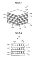
- FIG. 5-1 is a perspective view that schematically depicts an example of a heat exchange element that includes an air duct having a rectangular cross section; and FIG. 5-2 is a front view that schematically depicts the heat exchange element shown in FIG. 5-1 .
- a heat exchange element 113 shown the figures is configured such that a plurality of spacing members 113b shaped in flat plate standing on each one of partition members 113a forms one unit, and a plurality of units is layered; and a top plate 113c in the same configuration as the partition member 113a is layered on the top of the units.
- the former is arranged on the indoor side, and the latter is arranged on the outdoor side.
- the heat exchange ventilator according to the present invention can include a bypass air duct for performing ventilation without passing through the heat exchange element, for example in spring or autumn when temperature and humidity differences between indoors and outdoors are small, and an air-duct switching device that controls an opening and a closing of the bypass air duct.
- an air-duct switching unit to be used for performing a defrost operation, a filter to be used for air cleaning, or the like can be included.
- various modifications, decorations, and combinations can be applied to the heat exchange ventilator according to the present invention. The present invention is explained below in more detail with reference to examples.
- a nonporous hydrophilic polymer thin film was produced by thinly coating a polyurethane resin containing an oxyethylene group on a surface of a porous sheet of 25 ⁇ m in thickness made from polytetrafluoroethylene; and then a compound moisture penetration film that air-permeable nonwoven fabric was adhered by spot gluing on the back surface of the hydrophilic polymer thin film was used; so that partition members in a total heat exchange element to be arranged on the outdoor side were manufactured. Spacing members were manufactured by using a sheet of approximately 100 ⁇ m in thickness that pulp and fiber of a polyethylene resin were mixed. The pitch P of an air duct in the total heat exchange element was approximately 4.3 mm, and the height H (see FIG. 3-2 ) was approximately 1.8 mm.
- the total heat exchange element is hereinafter referred to as an "element I-A".
- Partition members in a total heat exchange element to be arranged on the indoor side were manufactured from specially-processed paper having a weighing capacity 20 g/m 2 added with a moisture absorbent processed by beating cellulose fiber (pulp) to have 200 seconds/100 cm 3 or more of the Gurley air permeability as a single partition member; and spacing members were manufactured from flame-retardant paper having a basis weight 70 g/m 2 .
- the pitch P of an air duct in the total heat exchange element was approximately 6.0 mm, and the height H was approximately 2.4 mm.
- the total heat exchange element is hereinafter referred to as an "element II-B".
- Sizes and shapes of the partition members and the spacing members in a plan view were made to be the same between the element I-A and the element II-A; and a total number of layers of the partition members and the spacing members in each of the element I-A and the element II-B was controlled such that respective heights of the element I-A and the element II-B were to be equal.
- a total heat exchange element having the same configuration as the element I-A explained in Example 1 except that the pitch P of a flow route of an air flow was approximately 6.0 mm and the height H was approximately 2.4 mm (hereinafter, the total heat exchange element is referred to as an "element I-B") was manufactured and arranged on the outdoor side, and the others were made similar to Example 1; so that a heat exchange ventilator was obtained.
- a heat exchange ventilator was obtained by manufacturing the element I-B explained in Example 2 and arranging it on the indoor side, and leaving the others similar to Example 1.
- Example 2 By using the element I-B explained in Example 2, a heat exchange ventilator configured similarly to the heat exchange ventilator 50A shown in FIG. 1 except to include only the element I-B as a heat exchange element was obtained. The size of each of horizontal partitions and each of vertical partitions in the housing was appropriately adjusted not to produce gap between a partition and a heat exchange unit.
- a heat exchange ventilator was obtained similarly to Example 2, except by using the element I-B also as a heat exchange element on the indoor side.
- a heat exchange ventilator was obtained similarly to Example 1, except by using the element I-A also as a heat exchange element on the indoor side.
- the average pressure-loss increase-speed ratio is a ratio where an average pressure-loss increase-speed in the heat exchange ventilator of Reference Example 2 is assumed at "1".
- Letter "T” in the expression denotes an elapse time from when the pressure loss PD 1 is measured until when the pressure loss PD 2 is measured.
- FIG. 6 An example of respective measurement results of variations with time in before-and-after differential pressure in a heat exchange element on which condensation and frost is controlled, and variations with time in before-and-after differential pressure in a heat exchange element on which condensation and frost is in progress, is shown in FIG. 6 .
- Respective measurement results of a total heat exchange efficiency and an average pressure-loss increase-speed ratio obtained with respect to each of the heat exchange ventilators described above are shown in FIG. 7 .
- the heat exchange ventilators according to the present invention are preferable as a heat exchange ventilator for household use and a heat exchange ventilator for commercial use, and particularly suitable as a heat exchange ventilator to be used in a cold district.
Landscapes
- Engineering & Computer Science (AREA)
- Chemical & Material Sciences (AREA)
- Combustion & Propulsion (AREA)
- Mechanical Engineering (AREA)
- General Engineering & Computer Science (AREA)
- Heat-Exchange Devices With Radiators And Conduit Assemblies (AREA)
Applications Claiming Priority (1)
| Application Number | Priority Date | Filing Date | Title |
|---|---|---|---|
| PCT/JP2008/057446 WO2009128150A1 (fr) | 2008-04-16 | 2008-04-16 | Appareil de ventilation à échange de chaleur |
Publications (2)
| Publication Number | Publication Date |
|---|---|
| EP2275751A1 true EP2275751A1 (fr) | 2011-01-19 |
| EP2275751A4 EP2275751A4 (fr) | 2017-03-22 |
Family
ID=41198862
Family Applications (1)
| Application Number | Title | Priority Date | Filing Date |
|---|---|---|---|
| EP08740522.1A Ceased EP2275751A4 (fr) | 2008-04-16 | 2008-04-16 | Appareil de ventilation à échange de chaleur |
Country Status (6)
| Country | Link |
|---|---|
| US (1) | US20110036541A1 (fr) |
| EP (1) | EP2275751A4 (fr) |
| JP (1) | JP5220102B2 (fr) |
| KR (1) | KR20100120313A (fr) |
| CN (1) | CN102007346B (fr) |
| WO (1) | WO2009128150A1 (fr) |
Cited By (9)
| Publication number | Priority date | Publication date | Assignee | Title |
|---|---|---|---|---|
| LT5884B (lt) | 2011-03-17 | 2012-11-26 | Andrius Baliukonis | Vėdinimo įrenginys |
| CN103438540A (zh) * | 2013-09-18 | 2013-12-11 | 河南科技大学 | 一种室内温湿度调节方法 |
| ITVR20130219A1 (it) * | 2013-09-25 | 2015-03-26 | Moratelli Helmut | Apparecchiatura per il ricambio di aria |
| EP3173704A3 (fr) * | 2015-10-21 | 2017-07-19 | Howatherm Klimatechnik GmbH | Installation de ventilation comprenant au moins un echangeur thermique a paroi de separation et procede de recuperation de chaleur a l'aide de surfaces d'echange fixes |
| EP3214254A1 (fr) * | 2016-03-03 | 2017-09-06 | Skaala Production Oy | Dispositif de ventilation, fenêtre de ventilation et échangeur de chaleur |
| WO2017162044A1 (fr) * | 2016-03-21 | 2017-09-28 | 王丙发 | Échangeur de chaleur |
| WO2017192038A1 (fr) * | 2016-05-03 | 2017-11-09 | Recair Holding B.V. | Récupérateur destiné à échanger de l'énergie entre deux écoulements d'air |
| EP3259536A4 (fr) * | 2015-02-20 | 2018-09-19 | FläktGroup Sweden AB | Dispositif de récupération de chaleur et procédé pour l'utilisation d'une hauteur disponible du dispositif dans une unité de traitement de l'air |
| WO2020178205A1 (fr) * | 2019-03-01 | 2020-09-10 | Martin Endhardt | Système de ventilation |
Families Citing this family (35)
| Publication number | Priority date | Publication date | Assignee | Title |
|---|---|---|---|---|
| SI23299A (sl) * | 2010-02-23 | 2011-08-31 | Mik, D.O.O. | Prezračevalna naprava |
| KR20110118367A (ko) * | 2010-04-23 | 2011-10-31 | (주)엘지하우시스 | 공기청정 기능을 구비한 창호용 환기 장치 |
| KR20110118369A (ko) * | 2010-04-23 | 2011-10-31 | (주)엘지하우시스 | 하이브리드 통풍 방식의 창호용 환기 장치 |
| KR101338547B1 (ko) * | 2010-04-23 | 2013-12-16 | (주)엘지하우시스 | 창호용 환기 장치의 열교환 소자 및 이를 포함하는 열교환 모듈 |
| KR101319224B1 (ko) | 2010-12-20 | 2013-10-16 | 다이킨 고교 가부시키가이샤 | 환기 장치 |
| EP2565550B1 (fr) * | 2011-09-01 | 2018-10-10 | LG Electronics Inc. | Dispositif de ventilation |
| WO2013116197A1 (fr) | 2012-02-02 | 2013-08-08 | Carrier Corporation | Ventilateur à récupération d'énergie et procédé de récupération d'énergie |
| US10222085B2 (en) | 2012-02-29 | 2019-03-05 | Carrier Corporation | Energy recovery ventilator with reduced power consumption |
| JP5925004B2 (ja) * | 2012-03-23 | 2016-05-25 | 大阪瓦斯株式会社 | 空調換気システム |
| JP5814844B2 (ja) * | 2012-03-26 | 2015-11-17 | 三菱電機株式会社 | 熱交換換気システム |
| CN103379800A (zh) * | 2012-04-27 | 2013-10-30 | 鸿富锦精密工业(深圳)有限公司 | 散热装置 |
| US9074789B2 (en) * | 2013-03-04 | 2015-07-07 | John P. Hanus | Method and apparatus to provide ventilation for a building |
| CN103307696B (zh) * | 2013-05-22 | 2015-06-24 | 苏州安岢栎热能科技有限公司 | 节能型窗台嵌入式空气换气机 |
| FR3011624B1 (fr) * | 2013-10-09 | 2017-12-22 | Commissariat Energie Atomique | Systeme et procede de traitement et de conditionnement d'air |
| FR3024533B1 (fr) * | 2014-07-31 | 2016-08-26 | Commissariat Energie Atomique | Echangeur enthalpique ameliore |
| WO2016046407A1 (fr) * | 2014-09-25 | 2016-03-31 | Heatex Ab | Unité d'échange de chaleur |
| US10527367B2 (en) * | 2015-08-14 | 2020-01-07 | Trane International Inc. | Heat exchange assembly in an air to air heat exchanger |
| US20180372361A1 (en) * | 2015-12-22 | 2018-12-27 | Panasonic Intellectual Property Management Co., Ltd. | Heat exchange type ventilation device |
| CN106839354B (zh) * | 2017-04-06 | 2022-11-01 | 际高科技有限公司 | 一种内循环热回收新风机组 |
| CN106871395B (zh) * | 2017-04-06 | 2022-11-01 | 际高科技有限公司 | 一种双板双冷源热回收新风机组 |
| JP6219549B1 (ja) * | 2017-05-09 | 2017-10-25 | 伸和コントロールズ株式会社 | 空気調和装置 |
| KR102087399B1 (ko) * | 2018-06-18 | 2020-03-10 | 최성철 | 현열 겸용 전열교환 환기장치 |
| JP6921324B2 (ja) * | 2018-06-18 | 2021-08-18 | 三菱電機株式会社 | 熱交換素子および熱交換換気装置 |
| KR102119510B1 (ko) * | 2018-06-19 | 2020-06-08 | 엔에이치엔 주식회사 | 공조 시스템 |
| KR102265397B1 (ko) | 2018-09-18 | 2021-06-15 | 주식회사 아모그린텍 | 환기장치용 열교환 유닛 |
| EP3754263B1 (fr) * | 2019-04-09 | 2023-09-06 | Tempeff Inc. | Appareil d'échange d'énergie pour chaleur sensible et latente |
| EP4080126A4 (fr) * | 2019-12-19 | 2024-04-24 | Panotec Co., Ltd. | Dispositif de climatisation intelligent pour réduire la micropoussière et les gaz nocifs |
| CN112228987A (zh) * | 2020-10-19 | 2021-01-15 | 静创美(北京)环保科技有限公司 | 一种双热回收毛细管辐射系统 |
| CN113465059B (zh) * | 2021-05-31 | 2023-02-03 | 华为数字能源技术有限公司 | 一种蒸发冷却机组及数据中心 |
| WO2022269821A1 (fr) * | 2021-06-23 | 2022-12-29 | 三菱電機株式会社 | Ventilateur d'échange de chaleur |
| WO2022269820A1 (fr) * | 2021-06-23 | 2022-12-29 | 三菱電機株式会社 | Dispositif de ventilation de type à échange de chaleur |
| JP7227516B2 (ja) * | 2021-06-29 | 2023-02-22 | ダイキン工業株式会社 | 換気装置 |
| US12247760B2 (en) * | 2022-03-28 | 2025-03-11 | Therma-Stor LLC | Energy recovery ventilation unit with a dehumidification system |
| KR102631466B1 (ko) * | 2022-06-16 | 2024-01-31 | 주식회사 엔이알 | 외기의 선택적 필터링이 가능한 창문형 복합기 |
| JPWO2024252775A1 (fr) * | 2023-06-07 | 2024-12-12 |
Family Cites Families (23)
| Publication number | Priority date | Publication date | Assignee | Title |
|---|---|---|---|---|
| US1601637A (en) * | 1926-02-16 | 1926-09-28 | John M Meigs | Refrigerator construction |
| US1825498A (en) * | 1929-04-22 | 1931-09-29 | Selmer F Wogan | Unit for heating, cooling, and ventilating system |
| DE3423736A1 (de) * | 1984-06-28 | 1986-01-02 | M.A.N. Maschinenfabrik Augsburg-Nürnberg AG, 8900 Augsburg | Kreuzstrom-plattenwaermetauscher |
| JPS61107020A (ja) | 1984-10-30 | 1986-05-24 | Matsushita Seiko Co Ltd | 空気調和機 |
| JPH0642051B2 (ja) | 1985-07-16 | 1994-06-01 | コニカ株式会社 | 写真感光材料 |
| CA1277173C (fr) * | 1985-12-12 | 1990-12-04 | Henry C. Buytendorp | Methode de traitement de produits alimentaires, recipients qui renferment lesdits produits, et produits alimentaires ainsi traites |
| JPS62138136U (fr) * | 1986-02-25 | 1987-08-31 | ||
| JP2707736B2 (ja) | 1989-04-10 | 1998-02-04 | 三菱マテリアル株式会社 | 単結晶育成方法 |
| US5660228A (en) * | 1995-12-12 | 1997-08-26 | Altech Energy | Modular air-to-air heat exchanger |
| JP2000146250A (ja) | 1998-10-30 | 2000-05-26 | Daikin Ind Ltd | 換気装置 |
| JP3791286B2 (ja) | 2000-02-23 | 2006-06-28 | 三菱電機株式会社 | 熱交換器付換気装置 |
| JP3543784B2 (ja) * | 2001-04-18 | 2004-07-21 | ダイキン工業株式会社 | 調湿換気装置 |
| JP2002349924A (ja) * | 2001-05-29 | 2002-12-04 | Kimura Kohki Co Ltd | 空調換気ユニット |
| US7188666B2 (en) * | 2003-02-04 | 2007-03-13 | Lg Electronics Inc. | Heat exchanger of ventilating system |
| JP2005291617A (ja) * | 2004-03-31 | 2005-10-20 | Nitta Ind Corp | 換気式熱交換器 |
| JP2005331193A (ja) | 2004-05-21 | 2005-12-02 | Fujitsu General Ltd | 換気装置 |
| TWI295359B (en) * | 2004-12-17 | 2008-04-01 | Foxconn Tech Co Ltd | Total heat exchanger |
| KR100628058B1 (ko) | 2005-05-31 | 2006-09-27 | 엘지전자 주식회사 | 전열교환기 및 이를 이용한 환기시스템 |
| JP2007170712A (ja) | 2005-12-20 | 2007-07-05 | Matsushita Electric Ind Co Ltd | 熱交換形換気装置 |
| KR100705670B1 (ko) * | 2006-03-20 | 2007-04-09 | 주식회사 대우일렉트로닉스 | 다수의 열교환부를 갖는 폐열회수 환기장치 |
| JP4872428B2 (ja) * | 2006-04-14 | 2012-02-08 | ダイキン工業株式会社 | 換気装置 |
| KR100762511B1 (ko) * | 2006-04-24 | 2007-10-02 | 주식회사 대우일렉트로닉스 | 핀 피치가 다른 열교환부를 갖는 폐열회수 환기장치 |
| JP4393478B2 (ja) * | 2006-06-09 | 2010-01-06 | 新日本空調株式会社 | デシカント換気システム |
-
2008
- 2008-04-16 JP JP2010508065A patent/JP5220102B2/ja active Active
- 2008-04-16 KR KR1020107022344A patent/KR20100120313A/ko not_active Ceased
- 2008-04-16 EP EP08740522.1A patent/EP2275751A4/fr not_active Ceased
- 2008-04-16 US US12/936,806 patent/US20110036541A1/en not_active Abandoned
- 2008-04-16 CN CN200880128660.0A patent/CN102007346B/zh not_active Expired - Fee Related
- 2008-04-16 WO PCT/JP2008/057446 patent/WO2009128150A1/fr not_active Ceased
Non-Patent Citations (2)
| Title |
|---|
| None |
| See also references of WO2009128150A1 |
Cited By (13)
| Publication number | Priority date | Publication date | Assignee | Title |
|---|---|---|---|---|
| LT5884B (lt) | 2011-03-17 | 2012-11-26 | Andrius Baliukonis | Vėdinimo įrenginys |
| CN103438540A (zh) * | 2013-09-18 | 2013-12-11 | 河南科技大学 | 一种室内温湿度调节方法 |
| CN103438540B (zh) * | 2013-09-18 | 2016-06-15 | 河南科技大学 | 一种室内温湿度调节方法 |
| ITVR20130219A1 (it) * | 2013-09-25 | 2015-03-26 | Moratelli Helmut | Apparecchiatura per il ricambio di aria |
| WO2015044884A1 (fr) * | 2013-09-25 | 2015-04-02 | Moratelli, Helmut | Appareil de renouvellement d'air |
| EP3259536A4 (fr) * | 2015-02-20 | 2018-09-19 | FläktGroup Sweden AB | Dispositif de récupération de chaleur et procédé pour l'utilisation d'une hauteur disponible du dispositif dans une unité de traitement de l'air |
| EP3173704A3 (fr) * | 2015-10-21 | 2017-07-19 | Howatherm Klimatechnik GmbH | Installation de ventilation comprenant au moins un echangeur thermique a paroi de separation et procede de recuperation de chaleur a l'aide de surfaces d'echange fixes |
| EP3214254A1 (fr) * | 2016-03-03 | 2017-09-06 | Skaala Production Oy | Dispositif de ventilation, fenêtre de ventilation et échangeur de chaleur |
| WO2017162044A1 (fr) * | 2016-03-21 | 2017-09-28 | 王丙发 | Échangeur de chaleur |
| WO2017192038A1 (fr) * | 2016-05-03 | 2017-11-09 | Recair Holding B.V. | Récupérateur destiné à échanger de l'énergie entre deux écoulements d'air |
| NL2016731B1 (nl) * | 2016-05-03 | 2017-11-10 | Recair Holding B V | Inrichting voor het uitwisselen van energie tussen twee luchtstromen. |
| CN109416190A (zh) * | 2016-05-03 | 2019-03-01 | 雷开尔控股有限公司 | 用于在两股气流之间交换能量的换热器 |
| WO2020178205A1 (fr) * | 2019-03-01 | 2020-09-10 | Martin Endhardt | Système de ventilation |
Also Published As
| Publication number | Publication date |
|---|---|
| JP5220102B2 (ja) | 2013-06-26 |
| WO2009128150A1 (fr) | 2009-10-22 |
| JPWO2009128150A1 (ja) | 2011-08-04 |
| EP2275751A4 (fr) | 2017-03-22 |
| CN102007346B (zh) | 2014-02-26 |
| KR20100120313A (ko) | 2010-11-15 |
| CN102007346A (zh) | 2011-04-06 |
| US20110036541A1 (en) | 2011-02-17 |
Similar Documents
| Publication | Publication Date | Title |
|---|---|---|
| EP2275751A1 (fr) | Appareil de ventilation à échange de chaleur | |
| US6845629B1 (en) | Vertical counterflow evaporative cooler | |
| US6405543B2 (en) | High-efficiency air-conditioning system with high-volume air distribution | |
| JP4409914B2 (ja) | 空気調和機の冷暖房システム | |
| CN101680675B (zh) | 热交换式换气装置 | |
| CN101384859B (zh) | 冷却及通风装置 | |
| CN101900377B (zh) | 换气装置及换气装置的控制方法 | |
| US20150323216A1 (en) | A heat exchanger and a ventilation assembly comprising it | |
| EP1485657B1 (fr) | Recuperateur de chaleur avec protection contre le gel | |
| CN101454616A (zh) | 空调装置 | |
| CN107869928A (zh) | 空气‑空气换热器及其制冷装置 | |
| KR101186152B1 (ko) | 냉각/제습열 회수기술을 이용한 항온항습기 | |
| KR101037871B1 (ko) | 냉각/제습열 회수기술을 이용한 공조기 | |
| JP3614775B2 (ja) | ヒートポンプ式空調機 | |
| RU2449223C1 (ru) | Теплообменный вентилятор | |
| CN113465059A (zh) | 一种蒸发冷却机组及数据中心 | |
| CN204063373U (zh) | 多级热回收新风处理装置 | |
| JP3008941B1 (ja) | 調湿換気装置 | |
| JP2007315712A (ja) | 空調装置及び建物 | |
| CN213687065U (zh) | 一种新风空调系统 | |
| CN213514267U (zh) | 一种多功能室内空气调节机组 | |
| CN104089393A (zh) | 除湿量可调的室内换热器及室内机 | |
| CN117029240A (zh) | 全热交换芯体及新风机 | |
| JP4997830B2 (ja) | 空調装置及び建物 | |
| JP2704183B2 (ja) | 空気調和装置 |
Legal Events
| Date | Code | Title | Description |
|---|---|---|---|
| PUAI | Public reference made under article 153(3) epc to a published international application that has entered the european phase |
Free format text: ORIGINAL CODE: 0009012 |
|
| 17P | Request for examination filed |
Effective date: 20101006 |
|
| AK | Designated contracting states |
Kind code of ref document: A1 Designated state(s): AT BE BG CH CY CZ DE DK EE ES FI FR GB GR HR HU IE IS IT LI LT LU LV MC MT NL NO PL PT RO SE SI SK TR |
|
| AX | Request for extension of the european patent |
Extension state: AL BA MK RS |
|
| DAX | Request for extension of the european patent (deleted) | ||
| RA4 | Supplementary search report drawn up and despatched (corrected) |
Effective date: 20170220 |
|
| RIC1 | Information provided on ipc code assigned before grant |
Ipc: F24F 12/00 20060101ALI20170214BHEP Ipc: F24F 7/08 20060101AFI20170214BHEP Ipc: F24F 13/30 20060101ALI20170214BHEP |
|
| TPAC | Observations filed by third parties |
Free format text: ORIGINAL CODE: EPIDOSNTIPA |
|
| STAA | Information on the status of an ep patent application or granted ep patent |
Free format text: STATUS: EXAMINATION IS IN PROGRESS |
|
| 17Q | First examination report despatched |
Effective date: 20180822 |
|
| REG | Reference to a national code |
Ref country code: DE Ref legal event code: R003 |
|
| STAA | Information on the status of an ep patent application or granted ep patent |
Free format text: STATUS: THE APPLICATION HAS BEEN REFUSED |
|
| 18R | Application refused |
Effective date: 20201009 |