EP2276044B1 - Commutateur à coulisse - Google Patents
Commutateur à coulisse Download PDFInfo
- Publication number
- EP2276044B1 EP2276044B1 EP10168923.0A EP10168923A EP2276044B1 EP 2276044 B1 EP2276044 B1 EP 2276044B1 EP 10168923 A EP10168923 A EP 10168923A EP 2276044 B1 EP2276044 B1 EP 2276044B1
- Authority
- EP
- European Patent Office
- Prior art keywords
- plunger
- push switch
- fixedly arranged
- spring
- further element
- Prior art date
- Legal status (The legal status is an assumption and is not a legal conclusion. Google has not performed a legal analysis and makes no representation as to the accuracy of the status listed.)
- Not-in-force
Links
Images




Classifications
-
- H—ELECTRICITY
- H01—ELECTRIC ELEMENTS
- H01H—ELECTRIC SWITCHES; RELAYS; SELECTORS; EMERGENCY PROTECTIVE DEVICES
- H01H3/00—Mechanisms for operating contacts
- H01H3/32—Driving mechanisms, i.e. for transmitting driving force to the contacts
- H01H3/50—Driving mechanisms, i.e. for transmitting driving force to the contacts with indexing or locating means, e.g. indexing by ball and spring
-
- H—ELECTRICITY
- H01—ELECTRIC ELEMENTS
- H01H—ELECTRIC SWITCHES; RELAYS; SELECTORS; EMERGENCY PROTECTIVE DEVICES
- H01H11/00—Apparatus or processes specially adapted for the manufacture of electric switches
- H01H11/0006—Apparatus or processes specially adapted for the manufacture of electric switches for converting electric switches
-
- H—ELECTRICITY
- H01—ELECTRIC ELEMENTS
- H01H—ELECTRIC SWITCHES; RELAYS; SELECTORS; EMERGENCY PROTECTIVE DEVICES
- H01H15/00—Switches having rectilinearly-movable operating part or parts adapted for actuation in opposite directions, e.g. slide switch
- H01H15/24—Switches having rectilinearly-movable operating part or parts adapted for actuation in opposite directions, e.g. slide switch having a single operating part only protruding from one side of the switch casing for alternate pushing and pulling
-
- H—ELECTRICITY
- H01—ELECTRIC ELEMENTS
- H01H—ELECTRIC SWITCHES; RELAYS; SELECTORS; EMERGENCY PROTECTIVE DEVICES
- H01H15/00—Switches having rectilinearly-movable operating part or parts adapted for actuation in opposite directions, e.g. slide switch
- H01H15/02—Details
- H01H15/06—Movable parts; Contacts mounted thereon
Definitions
- the invention relates to a slide switch with the features of claim 1. It is shown a slide switch, which has a better power distribution.
- the slide switch consists of a fixed part and a part displaceable to the fixed part, wherein the displaceable part is displaceable in at least one plane to the fixed part.
- slide switches comprising a slider with moving contacts and a base part or housing with stationary contacts.
- a switching function when the movable contacts are connected to or disconnected from the stationary contacts, a switching function, a mode switching function, or other electrical function are performed.
- a conventional slide switch for example, for use in a dictation machine, consists of two parts, a displaceable part, which is movably mounted, and a fixed part relative to the movable part, the so-called detent gate.
- the movable part is moved over the detent gate; it can be moved over this.
- the detent gate here has elevations and depressions over which the displaceable part slides.
- the sliding part dives when moving over the detent gate in their wells.
- the displaceable part in this case has a resilient element, which allows the displaceable part the difference between elevations and depressions of the Rastkulisse overcomes. If the displaceable part is positioned in the recess, electrical contact points of the displaceable part are connected to corresponding contact points. It is thus closed via these contact points when latched in the recess of the detent gate contact.
- Out EP 1 126 482 B1 is a multidirectional slide switch known. This has a housing with a fixed contact part and a first sliding part and a second sliding part, which are arranged in a housing.
- the first slide member is slidably connected to the second slide member so that movement may be made only in the direction of one of two intersecting axes relative to the second slide member, the second slide member being movably disposed in the direction of the other of the two axes with respect to the housing is.
- the second sliding member is traceable by a return force of at least one return spring in a neutral position.
- the first sliding part is equipped with a control knob and a movable contact part.
- the first and second sliding parts are moved in the respective directions, the movable contact piece being brought into contact with the fixed contact piece and at least one of the additionally attached contact pieces depending on the direction in which the operation button is moved ,
- the first slide member is brought into the neutral position with respect to the second slide member at least by the return force of at least one return spring installed on the second slide member.
- Out DE 102 24 773 B4 is another slide switch known.
- This slide switch comprises a base part, wherein two guide grooves of predetermined length are arranged parallel to each other on a surface.
- the slider is mounted on the base, with the slider a slide body on which two guide grooves of a predetermined length are formed in parallel to each other in the lower surface so as to be symmetrical to the center on the lower surface.
- slide bridge formed of two lower and two upper bridge parts, the two lower bridge parts being slidably fitted along the two parallel guide grooves in the base part, and the two upper bridges slidably fitted along the two parallel guide grooves in the slide switch are.
- the contact spring has contact spring parts, which constitute movable contacts and are arranged radially at the same or unequal angle to a spring plate of the contact spring.
- the stationary and the movable contacts are arranged in the starting position so that they face each other.
- US-A-4,904,828 A is a slide switch, consisting of a sliding part and a fixed part known.
- the sliding member is displaceable within the fixed part in one direction and the sliding part has at least one further element which is firmly connected to the sliding part.
- at least one plunger is movably mounted, which is perpendicular to the direction of displacement of the sliding member by means of a spring is arranged displaceably and protrudes due to the opposing force of the spring at least one of the fixed element associated side.
- the fixed part wells are provided, in which the plunger slides in when moving.
- This switch consists of a fixed housing part and a displaceably mounted in the fixed housing part movable housing part.
- the movable housing part is arranged in the stationary housing part.
- a through hole is provided, in which there is a spring on which a ball is arranged in each case at the inlet openings of the through-bore.
- the balls By means of the balls, the movable element slides within the fixed element.
- recesses are provided, in which the balls move during the movement of the movable part within the fixed element and thus define a detent point.
- Out JP 58 101315 A discloses a slide switch, the slider is held by means of an electromagnetic lock on the end stop against a biased return spring.
- Out CN 2 924 759 Y is a slider disclosed. A stop of the slider is achieved by a locking of a prestressed locking element in holes that are actuated by the user.
- a disadvantage of all these sliding switches is that they have a predetermined by the design locking behavior and a given operating hardness. A user is not able to adjust the latching behavior of the slide switch to his needs. The hardness or the force which is to be used to move the slide switch from one detent point to the other, is not changeable. In addition, the operation of the known slide switch by design, a non-uniform force required, which often leads to tilting and felt jerky operation.
- Object of the present invention is to show slide switches, which have a particularly good operability for a user.
- the sliding switch according to the invention according to the independent claim 1 consists of a displaceable element, a so-called sliding part, and a fixed element.
- the sliding part is displaceable within the fixed element in a plane.
- the sliding part has at least one further element, which is firmly connected to the sliding part.
- at least one movably mounted plunger is arranged, which is arranged perpendicular to the displacement plane of the sliding part to the fixed element in the further element.
- the plunger protrudes from the further element at least one side assigned to the fixed element out of the further element.
- the fixedly arranged element has recesses which correspond to the protruding from the further element plunger, so that when moving the sliding member in the fixed element of the plunger introduced into one of the recesses and thus defines a detent point of the slide switch.
- the further element is rectangular, square, oval, round or polygonal.
- the sliding part with the further element and its at least one plunger and the fixed element with the recesses forms a detent gate.
- the detent gate in the slide switch can be flexibly designed. It can be selected by the recesses and the or the plunger a defined locking as a switching point.
- the shape of the slide and the depressions, the characteristic of the slide switch can be influenced.
- the characteristic of the slide switch can also be influenced influenced by a skillful selection of materials.
- the at least one plunger is resiliently mounted in another element. As a result, the characteristic of the slide switch can be influenced and determined by the selection of the spring and its property. Depending on the spring hardness, the detent points of the slide switch can be felt more or less for a user.
- the spring stiffness of the springs can be changed via an adjusting unit on the slide switch so that a user can set the characteristics of the slide switch and its latching behavior to his needs.
- the at least one plunger is mounted in the further element by means of a spring.
- the spring is an annular spring, a coil spring or a leaf spring.
- the further element has room for a plurality of plungers, which are mounted by means of spring and thereby the force distribution for latching of the further element in the fixed element on a (total) larger spring travel can take place.
- the plunger consists of a head part and a handle part, wherein the head part has a rounding with a defined radius. Due to the possibility of designing the plunger, the characteristics of the slide switch can be influenced. So can be selected by a strong rounding a deep immersion of the plunger in a depression.
- the plunger has a hammer-like shape or in the head part of a head-like shape with a ring broadening.
- the hammer-like shape ensures that the plunger generates a uniform friction when moving the slider over the fixed element and thus the slide switch has a smooth sliding behavior. Due to the configuration of the plunger in the head part with a plug-head-like shape is achieved that the plunger well into the wells of the fixed element initiates and generates a defined detent point.
- the ring widening prevents the ram from sliding out of the other element.
- the ring broadening prevents the plunger from protruding too far through the opening in the further element.
- the further element has openings into which a plunger is insertable, wherein the ring widening of the plunger is larger than the openings. It is also advantageous that the plunger is made of compressible material. This is a particularly good sliding behavior of the slide switch generated.
- the spring is arranged between the side walls of the further element, perpendicular to the plane of movement of the sliding part to the fixed element and the plunger with its stem part or the ring widening mechanically contacted the spring, so that the plunger with a defined force from the opening can be pressed against the fixed element.
- the slide switch can be installed in a device and / or that the device is a dictation machine or a mobile telephone or a device of consumer electronics or a device of the communication electronics.
- the sliding part has at least one contact point and / or that the at least one contact point of the sliding part with contact contact points in the fixed element closes a contact on contact.
- At least one contact point on the sliding part is present for each of the recesses of the fixed element, which closes a contact with contact with at least one mating contact point in or on the fixed element.
- the slide switch has a touch surface which rises above a housing of the device.
- the slide switch has at least two switching points.
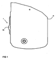
- FIG. 1 a device G with a housing H is shown in sections.
- the device G has a slide switch 1.
- the slide switch 1 has a touch surface 13.
- the touch surface 13 is raised relative to the housing H, so that a user can operate the slide switch 1 and easily reach.
- FIG. 2 is a device G with a slide switch 1 in an exploded view of the slide switch 1 is shown.
- the device G has two housing halves H, in which the slide switch 1 is inserted at the position O.
- the slide switch 1 has a touch surface 13.
- the slide switch 1 consists of a sliding part 2 and a fixedly arranged opposite this element 3.
- the sliding part 2 moves upon actuation of the slide switch 1 in a plane to the fixed element 3.
- the sliding part 2 has at least one further element 4, which firmly with the sliding part 2 is connectable.
- the further element 4 is rectangular, square, oval, round or n-shaped. But it can be used any other geometric shape.
- the further element 4 has an opening 12 into which the plunger 5 can be inserted and from which opening 12 the plunger 5 protrudes at least partially beyond the further element 4.
- the sliding part 2 further comprises springs 15, which are arranged in the direction of the plane of movement of the sliding part 2 to the fixed element 3 and the sliding part 2 at least partially project beyond.
- FIG. 3 is a Aufbruchanno a device G in the area of the slide switch 1 shown.
- two further elements 4 are integrated into the sliding part 2, which receive two plungers 5 each.
- the plunger 5 within a further element 4 are each offset from one another.
- Each of the two plungers 5 in a further element 4 projects in each case on a different side of the further element 4 in the manner described above.
- the fixed element 3 is easily recognizable.
- the fixed element 3 has at least one recess 6.
- the recesses 6 correspond to the plungers 5, which are arranged in the further element 4 of the sliding part 2.
- the plunger 5 slides this in the fixed element 3 existing openings 6.
- the plunger 5 slide into these openings 6 and form in this position latching positions of the slide switch 1 from.
- Each of these locking positions is associated with a contact pairing between fixedly arranged element 3 and sliding part 2, which then trigger a corresponding function in the device G.
- the characteristic of the slide switch 1 is adjustable.
- the characteristic of the slide switch 1 can be influenced. For each combination of depression 6 and plunger 5, a corresponding contact position and a corresponding contact closure between the sliding part 2 and fixed element 3 is provided.
- springs 15 are provided on the sliding part 2. In the end position of the slide switch 1, the respective spring 15 is pressed together and generates a counterforce. By the spring 15, the slide switch 1 does not remain in the end position, but jumps back to the previous position as soon as a user releases the slide switch 1 in the end position (end stop).
- FIG. 4 is a section through a device G and the housing H in the region of the slide switch 1 is shown. Again, the slider 2 and the fixed member 3 are shown. In addition, the further element 4, which is firmly connected to the sliding part 2, shown. There are in FIG. 4 two further elements 4 are shown, each with two opposing tappets 5, which slide along the arranged element 3 upon actuation of the slide switch 1 and sliding of the sliding member 2 in openings 6 of the fixed element 3. The openings 6 are in FIG. 4 not shown. By selecting two further elements 4, each with two tappets 5, a particularly uniform force distribution between the sliding part 2 and the fixed element 3 is provided. The springs 7 store the plunger 5 resiliently in another element. 4
- the force distribution for latching the further element 4 in the fixed element 3 on a (total) larger travel can be done or better distributed.
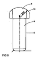
- a plunger 5 is shown in section.
- the plunger 5 is characterized by a head part 8 and a stem part 9.
- the head part 8 is wider than the stem part 9.
- the head part 8 has a rounding 10.
- a plunger 5 is shown in the form of a hammer.
- the head part 8 is parallelepiped-shaped with a rounding 10 in the upper region.
- the stem part 9 is firmly connected to the head part 8 and phased at the end.
- FIG. 7 shows a further embodiment of a plunger 5.
- the plunger 5 according to FIG. 7 again has a head part 8 and a stem part 9. Furthermore, a ring broadening 11 is present. The ring widening 11 is made wider than the opening 12 in the further element 4. In this way, a defined length of the projecting out of the plunger 5 from the further element 4 is given.
- FIG. 8 is a section through the plunger 5 according to FIG. 7 shown. Again, the ring broadening 11, the head part 8 with the rounding 10 and the stem part 9 are again shown here well.
Landscapes
- Engineering & Computer Science (AREA)
- Manufacturing & Machinery (AREA)
- Slide Switches (AREA)
- Push-Button Switches (AREA)
- Mechanisms For Operating Contacts (AREA)
Claims (10)
- Commutateur à coulisse (1) composé d'une partie coulissante (2) et d'un élément fixe (3), la partie coulissante (2) pouvant être déplacée à l'intérieur de l'élément fixe (3) dans un niveau de coulissement, la partie coulissante (2) présentant au moins un autre élément (4) qui peut être relié de manière fixe à la partie coulissante (2), et au moins un poussoir (5) à palier mobile étant situé dans l'autre élément (4) qui est disposé à la verticale du niveau de coulissement de la partie coulissante (2) par rapport à l'élément fixe (3) dans l'autre élément (4), le poussoir (5) sortant de l'autre élément (4) sur au moins l'un des côtés attribués à l'élément fixe (3), l'élément fixe (3) présentant des renfoncements (6) qui correspondent au poussoir (5) sortant de l'autre élément (4) si bien qu'en cas de mouvement de la partie coulissante (2) dans l'élément fixe (3), le poussoir (5) est introduit dans l'un des renfoncements (6) et définit ainsi un point d'enclenchement du commutateur à coulisse (1), le poussoir (5) étant composé d'une tête (8) et d'une tige (9) et la tête (8) présentant un arrondi (10) avec un rayon défini,
caractérisé en cela que le poussoir (5) présente dans la tête (8) une forme de tête enfichable avec un élargissement de bague (11) et l'autre élément (4) présentant des parois latérales avec des ouvertures (12) dans lesquelles le poussoir (5) peut être inséré, l'élargissement de bague (11) du poussoir (5) étant plus grand que l'ouverture (12), un ressort (7) étant placé entre les parois latérales de l'autre élément (4), à la verticale du niveau de mouvement de la partie coulissante (2) par rapport à l'élément fixe (3), et le poussoir (5) étant en contact mécanique par son élargissement de bague (11) avec le ressort (7), si bien que le poussoir (5) peut être appuyé avec une force définie à partir de l'ouverture (12) contre l'élément fixe (3). - Commutateur à coulisse (1) selon la revendication 1 caractérisé en cela que l'autre élément (4) est rectangulaire, carré, ovale, rond ou polygonal.
- Commutateur à coulisse (5) selon la revendication 1 ou 2 caractérisé en cela que la partie coulissante (2) forme une coulisse à trame avec l'autre élément (4) et au moins un poussoir (5) et l'élément fixe (3) avec les renfoncements (6) et/ou en cela qu'au moins un poussoir (5) est placé sur un palier à ressort dans l'autre élément (4).
- Commutateur à coulisse (1) selon la revendication 3 caractérisé en cela qu'au moins un poussoir (5) soit situé sur un palier dans l'autre élément (4) avec le ressort (7) et que le ressort (7) est un ressort à bague, à spirale ou à feuille.
- Commutateur à coulisse (1) selon l'une des revendications précédentes caractérisé en cela que l'autre élément (4) présente de la place pour plusieurs poussoirs (5) étant situés sur un palier à l'aide du ressort (7) et qu'ainsi la répartition pour l'enclenchement de l'autre élément (4) peut survenir dans l'élément fixe (3) sur une voie de ressort modifiable.
- Commutateur à coulisse (1) selon l'une des revendications précédentes caractérisé en cela que le commutateur à coulisse (1) peut être incorporé dans un appareil (G) et l'appareil (G) est un dictaphone ou un téléphone portable ou un appareil électronique de divertissement ou un appareil électronique de communication.
- Commutateur à coulisse (1) selon l'une des revendications précédentes caractérisé en cela que la partie coulissante (2) présente au moins un point de contact et qu'au moins un point de contact de la partie coulissante (2) ferme avec des contre-points de contact un contact par contact dans l'élément fixe (3).
- Commutateur à coulisse (1) selon l'une des revendications précédentes caractérisé en cela que pour chaque renfoncement (6) de l'élément fixe (3) il y a au moins un point de contact sur la partie coulissante (2) qui ferme un contact en cas de contact avec au moins un contre-point de contact dans ou sur l'élément fixe (3).
- Commutateur à coulisse (1) selon l'une des revendications précédentes caractérisé en cela que le commutateur à coulisse (1) présente une surface tactile (13) qui se trouve au-dessus d'un boîtier (H) de l'appareil (G).
- Commutateur à coulisse (1) selon l'une des revendications précédentes caractérisé en cela que le commutateur à coulisse (1) présente au moins deux points de commutation.
Priority Applications (1)
| Application Number | Priority Date | Filing Date | Title |
|---|---|---|---|
| EP11005529A EP2375430B1 (fr) | 2009-07-17 | 2010-07-08 | Interrupteur à coulisse |
Applications Claiming Priority (1)
| Application Number | Priority Date | Filing Date | Title |
|---|---|---|---|
| DE102009026191A DE102009026191A1 (de) | 2009-07-17 | 2009-07-17 | Schiebeschalter |
Related Child Applications (1)
| Application Number | Title | Priority Date | Filing Date |
|---|---|---|---|
| EP11005529A Division-Into EP2375430B1 (fr) | 2009-07-17 | 2010-07-08 | Interrupteur à coulisse |
Publications (3)
| Publication Number | Publication Date |
|---|---|
| EP2276044A2 EP2276044A2 (fr) | 2011-01-19 |
| EP2276044A3 EP2276044A3 (fr) | 2011-04-20 |
| EP2276044B1 true EP2276044B1 (fr) | 2014-10-29 |
Family
ID=42938168
Family Applications (2)
| Application Number | Title | Priority Date | Filing Date |
|---|---|---|---|
| EP10168923.0A Not-in-force EP2276044B1 (fr) | 2009-07-17 | 2010-07-08 | Commutateur à coulisse |
| EP11005529A Not-in-force EP2375430B1 (fr) | 2009-07-17 | 2010-07-08 | Interrupteur à coulisse |
Family Applications After (1)
| Application Number | Title | Priority Date | Filing Date |
|---|---|---|---|
| EP11005529A Not-in-force EP2375430B1 (fr) | 2009-07-17 | 2010-07-08 | Interrupteur à coulisse |
Country Status (2)
| Country | Link |
|---|---|
| EP (2) | EP2276044B1 (fr) |
| DE (2) | DE102009061041B4 (fr) |
Family Cites Families (9)
| Publication number | Priority date | Publication date | Assignee | Title |
|---|---|---|---|---|
| JPS5021676U (fr) * | 1973-06-21 | 1975-03-11 | ||
| JPS58101315A (ja) | 1981-12-11 | 1983-06-16 | Matsushita Electric Ind Co Ltd | 摺動式電気部品 |
| DE8702343U1 (de) * | 1987-02-16 | 1987-04-02 | Hella KG Hueck & Co, 4780 Lippstadt | Innenleuchte für Fahrzeuge mit einem Schiebeschalter |
| US4904828A (en) | 1988-09-23 | 1990-02-27 | Emhart Industries, Inc. | Multi-circuit slide switch assembly with distinct plunger operated switch |
| JP2001307599A (ja) | 2000-02-15 | 2001-11-02 | Alps Electric Co Ltd | 多方向スライドスイッチ |
| JP2003059374A (ja) | 2001-06-04 | 2003-02-28 | Mic Electron Co | スライドスイッチ |
| US6597796B2 (en) * | 2001-11-09 | 2003-07-22 | Chao-Chih Chang | Microphone with a variable resistance switch |
| US6930268B1 (en) * | 2002-05-20 | 2005-08-16 | Robert M. Tuniewicz | On-off electrical switch having quick make-brake spring loaded plunger mechanism |
| CN2924759Y (zh) | 2006-04-25 | 2007-07-18 | 康舒科技股份有限公司 | 具有强制保护措施的电压选择开关 |
-
2009
- 2009-07-17 DE DE102009061041.3A patent/DE102009061041B4/de not_active Expired - Fee Related
- 2009-07-17 DE DE102009026191A patent/DE102009026191A1/de not_active Withdrawn
-
2010
- 2010-07-08 EP EP10168923.0A patent/EP2276044B1/fr not_active Not-in-force
- 2010-07-08 EP EP11005529A patent/EP2375430B1/fr not_active Not-in-force
Also Published As
| Publication number | Publication date |
|---|---|
| DE102009061041B4 (de) | 2018-10-31 |
| EP2276044A3 (fr) | 2011-04-20 |
| DE102009061041A1 (de) | 2011-01-27 |
| DE102009026191A1 (de) | 2011-01-27 |
| EP2375430B1 (fr) | 2012-12-05 |
| EP2375430A1 (fr) | 2011-10-12 |
| EP2276044A2 (fr) | 2011-01-19 |
Similar Documents
| Publication | Publication Date | Title |
|---|---|---|
| DE10324295B4 (de) | Elektrischer Schalter | |
| DE2346392A1 (de) | Tastatur, insbesondere fuer elektronische rechengeraete | |
| DE2330730A1 (de) | Schalttaste mit einem magnetschaltwerk | |
| DE3208559C2 (de) | Tastatur | |
| DE19829811C2 (de) | Mehrrichtungs-Eingabevorrichtung | |
| DE3613702C2 (fr) | ||
| DE2537284A1 (de) | Prellfreier elektrischer schalter | |
| EP0344625B1 (fr) | Interrupteur à bouton-poussoir | |
| DE102013107001B4 (de) | Betätigungseinrichtung für ein Kraftfahrzeug | |
| DE2942720C2 (de) | Drucktaste mit Schnappwirkung | |
| DE3442173A1 (de) | Elektrischer schalter gedrungener bauart | |
| EP2375430B1 (fr) | Interrupteur à coulisse | |
| DE102021112594A1 (de) | Tastatur sowie zugehörige Taste und zugehöriger Einstellmechanismus | |
| DE102010012908B4 (de) | Multifunktionsschalter | |
| EP2228811A2 (fr) | Insert de commutateur d'un appareil d'installation électrique | |
| DE102009026214B4 (de) | Schiebeschalter | |
| DE3900394C2 (fr) | ||
| DE3107316A1 (de) | "schiebeschalter" | |
| DE10247093B3 (de) | Navigationsschalter | |
| DE10032518C1 (de) | Mehrstufige elektrische Schaltvorrichtung | |
| DE20117514U1 (de) | Wippenschalter | |
| EP1995746B1 (fr) | Commutateur à curseur | |
| DE102023109472B3 (de) | Nottasteinrichtung einer Türverriegelung mit einem Notausschalter | |
| DE3111407A1 (de) | Tastenschalter | |
| EP1501108A1 (fr) | Interrupteur multidirectionnel |
Legal Events
| Date | Code | Title | Description |
|---|---|---|---|
| PUAI | Public reference made under article 153(3) epc to a published international application that has entered the european phase |
Free format text: ORIGINAL CODE: 0009012 |
|
| AK | Designated contracting states |
Kind code of ref document: A2 Designated state(s): AL AT BE BG CH CY CZ DE DK EE ES FI FR GB GR HR HU IE IS IT LI LT LU LV MC MK MT NL NO PL PT RO SE SI SK SM TR |
|
| AX | Request for extension of the european patent |
Extension state: BA ME RS |
|
| PUAL | Search report despatched |
Free format text: ORIGINAL CODE: 0009013 |
|
| AK | Designated contracting states |
Kind code of ref document: A3 Designated state(s): AL AT BE BG CH CY CZ DE DK EE ES FI FR GB GR HR HU IE IS IT LI LT LU LV MC MK MT NL NO PL PT RO SE SI SK SM TR |
|
| AX | Request for extension of the european patent |
Extension state: BA ME RS |
|
| RIC1 | Information provided on ipc code assigned before grant |
Ipc: H01H 3/50 20060101AFI20101022BHEP Ipc: H01H 15/24 20060101ALI20110316BHEP Ipc: H01H 11/00 20060101ALI20110316BHEP |
|
| DAC | Divisional application: reference to earlier application (deleted) | ||
| 17P | Request for examination filed |
Effective date: 20111020 |
|
| 17Q | First examination report despatched |
Effective date: 20140206 |
|
| RIC1 | Information provided on ipc code assigned before grant |
Ipc: H01H 15/24 20060101ALI20140411BHEP Ipc: H01H 11/00 20060101ALI20140411BHEP Ipc: H01H 3/50 20060101AFI20140411BHEP Ipc: H01H 15/06 20060101ALN20140411BHEP |
|
| GRAP | Despatch of communication of intention to grant a patent |
Free format text: ORIGINAL CODE: EPIDOSNIGR1 |
|
| INTG | Intention to grant announced |
Effective date: 20140602 |
|
| GRAS | Grant fee paid |
Free format text: ORIGINAL CODE: EPIDOSNIGR3 |
|
| GRAA | (expected) grant |
Free format text: ORIGINAL CODE: 0009210 |
|
| AK | Designated contracting states |
Kind code of ref document: B1 Designated state(s): AL AT BE BG CH CY CZ DE DK EE ES FI FR GB GR HR HU IE IS IT LI LT LU LV MC MK MT NL NO PL PT RO SE SI SK SM TR |
|
| REG | Reference to a national code |
Ref country code: GB Ref legal event code: FG4D Free format text: NOT ENGLISH |
|
| REG | Reference to a national code |
Ref country code: CH Ref legal event code: EP |
|
| REG | Reference to a national code |
Ref country code: AT Ref legal event code: REF Ref document number: 693922 Country of ref document: AT Kind code of ref document: T Effective date: 20141115 |
|
| REG | Reference to a national code |
Ref country code: IE Ref legal event code: FG4D Free format text: LANGUAGE OF EP DOCUMENT: GERMAN |
|
| REG | Reference to a national code |
Ref country code: DE Ref legal event code: R096 Ref document number: 502010008132 Country of ref document: DE Effective date: 20141204 |
|
| REG | Reference to a national code |
Ref country code: SE Ref legal event code: TRGR |
|
| REG | Reference to a national code |
Ref country code: NL Ref legal event code: T3 |
|
| REG | Reference to a national code |
Ref country code: LT Ref legal event code: MG4D |
|
| PG25 | Lapsed in a contracting state [announced via postgrant information from national office to epo] |
Ref country code: FI Free format text: LAPSE BECAUSE OF FAILURE TO SUBMIT A TRANSLATION OF THE DESCRIPTION OR TO PAY THE FEE WITHIN THE PRESCRIBED TIME-LIMIT Effective date: 20141029 Ref country code: LT Free format text: LAPSE BECAUSE OF FAILURE TO SUBMIT A TRANSLATION OF THE DESCRIPTION OR TO PAY THE FEE WITHIN THE PRESCRIBED TIME-LIMIT Effective date: 20141029 Ref country code: NO Free format text: LAPSE BECAUSE OF FAILURE TO SUBMIT A TRANSLATION OF THE DESCRIPTION OR TO PAY THE FEE WITHIN THE PRESCRIBED TIME-LIMIT Effective date: 20150129 Ref country code: PT Free format text: LAPSE BECAUSE OF FAILURE TO SUBMIT A TRANSLATION OF THE DESCRIPTION OR TO PAY THE FEE WITHIN THE PRESCRIBED TIME-LIMIT Effective date: 20150302 Ref country code: IS Free format text: LAPSE BECAUSE OF FAILURE TO SUBMIT A TRANSLATION OF THE DESCRIPTION OR TO PAY THE FEE WITHIN THE PRESCRIBED TIME-LIMIT Effective date: 20150228 Ref country code: ES Free format text: LAPSE BECAUSE OF FAILURE TO SUBMIT A TRANSLATION OF THE DESCRIPTION OR TO PAY THE FEE WITHIN THE PRESCRIBED TIME-LIMIT Effective date: 20141029 |
|
| PG25 | Lapsed in a contracting state [announced via postgrant information from national office to epo] |
Ref country code: GR Free format text: LAPSE BECAUSE OF FAILURE TO SUBMIT A TRANSLATION OF THE DESCRIPTION OR TO PAY THE FEE WITHIN THE PRESCRIBED TIME-LIMIT Effective date: 20150130 Ref country code: CY Free format text: LAPSE BECAUSE OF FAILURE TO SUBMIT A TRANSLATION OF THE DESCRIPTION OR TO PAY THE FEE WITHIN THE PRESCRIBED TIME-LIMIT Effective date: 20141029 Ref country code: PL Free format text: LAPSE BECAUSE OF FAILURE TO SUBMIT A TRANSLATION OF THE DESCRIPTION OR TO PAY THE FEE WITHIN THE PRESCRIBED TIME-LIMIT Effective date: 20141029 Ref country code: LV Free format text: LAPSE BECAUSE OF FAILURE TO SUBMIT A TRANSLATION OF THE DESCRIPTION OR TO PAY THE FEE WITHIN THE PRESCRIBED TIME-LIMIT Effective date: 20141029 Ref country code: HR Free format text: LAPSE BECAUSE OF FAILURE TO SUBMIT A TRANSLATION OF THE DESCRIPTION OR TO PAY THE FEE WITHIN THE PRESCRIBED TIME-LIMIT Effective date: 20141029 |
|
| REG | Reference to a national code |
Ref country code: FR Ref legal event code: PLFP Year of fee payment: 6 |
|
| REG | Reference to a national code |
Ref country code: DE Ref legal event code: R097 Ref document number: 502010008132 Country of ref document: DE |
|
| PG25 | Lapsed in a contracting state [announced via postgrant information from national office to epo] |
Ref country code: EE Free format text: LAPSE BECAUSE OF FAILURE TO SUBMIT A TRANSLATION OF THE DESCRIPTION OR TO PAY THE FEE WITHIN THE PRESCRIBED TIME-LIMIT Effective date: 20141029 Ref country code: RO Free format text: LAPSE BECAUSE OF FAILURE TO SUBMIT A TRANSLATION OF THE DESCRIPTION OR TO PAY THE FEE WITHIN THE PRESCRIBED TIME-LIMIT Effective date: 20141029 Ref country code: CZ Free format text: LAPSE BECAUSE OF FAILURE TO SUBMIT A TRANSLATION OF THE DESCRIPTION OR TO PAY THE FEE WITHIN THE PRESCRIBED TIME-LIMIT Effective date: 20141029 Ref country code: DK Free format text: LAPSE BECAUSE OF FAILURE TO SUBMIT A TRANSLATION OF THE DESCRIPTION OR TO PAY THE FEE WITHIN THE PRESCRIBED TIME-LIMIT Effective date: 20141029 Ref country code: SK Free format text: LAPSE BECAUSE OF FAILURE TO SUBMIT A TRANSLATION OF THE DESCRIPTION OR TO PAY THE FEE WITHIN THE PRESCRIBED TIME-LIMIT Effective date: 20141029 |
|
| PG25 | Lapsed in a contracting state [announced via postgrant information from national office to epo] |
Ref country code: IT Free format text: LAPSE BECAUSE OF FAILURE TO SUBMIT A TRANSLATION OF THE DESCRIPTION OR TO PAY THE FEE WITHIN THE PRESCRIBED TIME-LIMIT Effective date: 20141029 |
|
| PLBE | No opposition filed within time limit |
Free format text: ORIGINAL CODE: 0009261 |
|
| STAA | Information on the status of an ep patent application or granted ep patent |
Free format text: STATUS: NO OPPOSITION FILED WITHIN TIME LIMIT |
|
| 26N | No opposition filed |
Effective date: 20150730 |
|
| PG25 | Lapsed in a contracting state [announced via postgrant information from national office to epo] |
Ref country code: SI Free format text: LAPSE BECAUSE OF FAILURE TO SUBMIT A TRANSLATION OF THE DESCRIPTION OR TO PAY THE FEE WITHIN THE PRESCRIBED TIME-LIMIT Effective date: 20141029 Ref country code: MC Free format text: LAPSE BECAUSE OF FAILURE TO SUBMIT A TRANSLATION OF THE DESCRIPTION OR TO PAY THE FEE WITHIN THE PRESCRIBED TIME-LIMIT Effective date: 20141029 |
|
| REG | Reference to a national code |
Ref country code: CH Ref legal event code: PL |
|
| PG25 | Lapsed in a contracting state [announced via postgrant information from national office to epo] |
Ref country code: LU Free format text: LAPSE BECAUSE OF FAILURE TO SUBMIT A TRANSLATION OF THE DESCRIPTION OR TO PAY THE FEE WITHIN THE PRESCRIBED TIME-LIMIT Effective date: 20150708 |
|
| REG | Reference to a national code |
Ref country code: DE Ref legal event code: R082 Ref document number: 502010008132 Country of ref document: DE Representative=s name: DIE PATENTERIE GBR PATENT- UND RECHTSANWALTSSO, DE |
|
| REG | Reference to a national code |
Ref country code: IE Ref legal event code: MM4A |
|
| PG25 | Lapsed in a contracting state [announced via postgrant information from national office to epo] |
Ref country code: LI Free format text: LAPSE BECAUSE OF NON-PAYMENT OF DUE FEES Effective date: 20150731 Ref country code: CH Free format text: LAPSE BECAUSE OF NON-PAYMENT OF DUE FEES Effective date: 20150731 |
|
| REG | Reference to a national code |
Ref country code: FR Ref legal event code: PLFP Year of fee payment: 7 |
|
| PG25 | Lapsed in a contracting state [announced via postgrant information from national office to epo] |
Ref country code: IE Free format text: LAPSE BECAUSE OF NON-PAYMENT OF DUE FEES Effective date: 20150708 |
|
| PG25 | Lapsed in a contracting state [announced via postgrant information from national office to epo] |
Ref country code: MT Free format text: LAPSE BECAUSE OF FAILURE TO SUBMIT A TRANSLATION OF THE DESCRIPTION OR TO PAY THE FEE WITHIN THE PRESCRIBED TIME-LIMIT Effective date: 20141029 |
|
| PG25 | Lapsed in a contracting state [announced via postgrant information from national office to epo] |
Ref country code: SM Free format text: LAPSE BECAUSE OF FAILURE TO SUBMIT A TRANSLATION OF THE DESCRIPTION OR TO PAY THE FEE WITHIN THE PRESCRIBED TIME-LIMIT Effective date: 20141029 Ref country code: BG Free format text: LAPSE BECAUSE OF FAILURE TO SUBMIT A TRANSLATION OF THE DESCRIPTION OR TO PAY THE FEE WITHIN THE PRESCRIBED TIME-LIMIT Effective date: 20141029 Ref country code: HU Free format text: LAPSE BECAUSE OF FAILURE TO SUBMIT A TRANSLATION OF THE DESCRIPTION OR TO PAY THE FEE WITHIN THE PRESCRIBED TIME-LIMIT; INVALID AB INITIO Effective date: 20100708 |
|
| REG | Reference to a national code |
Ref country code: FR Ref legal event code: PLFP Year of fee payment: 8 |
|
| PG25 | Lapsed in a contracting state [announced via postgrant information from national office to epo] |
Ref country code: BE Free format text: LAPSE BECAUSE OF NON-PAYMENT OF DUE FEES Effective date: 20150731 |
|
| PG25 | Lapsed in a contracting state [announced via postgrant information from national office to epo] |
Ref country code: TR Free format text: LAPSE BECAUSE OF FAILURE TO SUBMIT A TRANSLATION OF THE DESCRIPTION OR TO PAY THE FEE WITHIN THE PRESCRIBED TIME-LIMIT Effective date: 20141029 |
|
| REG | Reference to a national code |
Ref country code: DE Ref legal event code: R082 Ref document number: 502010008132 Country of ref document: DE Representative=s name: DIE PATENTERIE GBR PATENT- UND RECHTSANWALTSSO, DE Ref country code: DE Ref legal event code: R081 Ref document number: 502010008132 Country of ref document: DE Owner name: GRUNDIG BUSINESS SYSTEMS GMBH, DE Free format text: FORMER OWNER: GBS HOLDING GMBH, 81827 MUENCHEN, DE |
|
| REG | Reference to a national code |
Ref country code: NL Ref legal event code: HC Owner name: GRUNDIG BUSINESS SYSTEMS GMBH; DE Free format text: DETAILS ASSIGNMENT: CHANGE OF OWNER(S), CHANGE OF OWNER(S) NAME; FORMER OWNER NAME: GBS HOLDING GMBH Effective date: 20180329 |
|
| REG | Reference to a national code |
Ref country code: GB Ref legal event code: 732E Free format text: REGISTERED BETWEEN 20180405 AND 20180411 |
|
| PG25 | Lapsed in a contracting state [announced via postgrant information from national office to epo] |
Ref country code: MK Free format text: LAPSE BECAUSE OF FAILURE TO SUBMIT A TRANSLATION OF THE DESCRIPTION OR TO PAY THE FEE WITHIN THE PRESCRIBED TIME-LIMIT Effective date: 20141029 |
|
| REG | Reference to a national code |
Ref country code: FR Ref legal event code: CA Effective date: 20180607 Ref country code: FR Ref legal event code: CD Owner name: GRUNDIG BUSINESS SYSTEMS GMBH, DE Effective date: 20180607 |
|
| REG | Reference to a national code |
Ref country code: FR Ref legal event code: PLFP Year of fee payment: 9 |
|
| REG | Reference to a national code |
Ref country code: AT Ref legal event code: PC Ref document number: 693922 Country of ref document: AT Kind code of ref document: T Owner name: GRUNDIG BUSINESS SYSTEMS GMBH, DE Effective date: 20180628 |
|
| PG25 | Lapsed in a contracting state [announced via postgrant information from national office to epo] |
Ref country code: AL Free format text: LAPSE BECAUSE OF FAILURE TO SUBMIT A TRANSLATION OF THE DESCRIPTION OR TO PAY THE FEE WITHIN THE PRESCRIBED TIME-LIMIT Effective date: 20141029 |
|
| PGFP | Annual fee paid to national office [announced via postgrant information from national office to epo] |
Ref country code: NL Payment date: 20210721 Year of fee payment: 12 |
|
| PGFP | Annual fee paid to national office [announced via postgrant information from national office to epo] |
Ref country code: AT Payment date: 20210728 Year of fee payment: 12 Ref country code: FR Payment date: 20210723 Year of fee payment: 12 |
|
| PGFP | Annual fee paid to national office [announced via postgrant information from national office to epo] |
Ref country code: GB Payment date: 20210722 Year of fee payment: 12 Ref country code: SE Payment date: 20210722 Year of fee payment: 12 Ref country code: DE Payment date: 20210720 Year of fee payment: 12 |
|
| REG | Reference to a national code |
Ref country code: DE Ref legal event code: R119 Ref document number: 502010008132 Country of ref document: DE |
|
| REG | Reference to a national code |
Ref country code: SE Ref legal event code: EUG |
|
| REG | Reference to a national code |
Ref country code: NL Ref legal event code: MM Effective date: 20220801 |
|
| REG | Reference to a national code |
Ref country code: AT Ref legal event code: MM01 Ref document number: 693922 Country of ref document: AT Kind code of ref document: T Effective date: 20220708 |
|
| GBPC | Gb: european patent ceased through non-payment of renewal fee |
Effective date: 20220708 |
|
| PG25 | Lapsed in a contracting state [announced via postgrant information from national office to epo] |
Ref country code: SE Free format text: LAPSE BECAUSE OF NON-PAYMENT OF DUE FEES Effective date: 20220709 Ref country code: FR Free format text: LAPSE BECAUSE OF NON-PAYMENT OF DUE FEES Effective date: 20220731 Ref country code: AT Free format text: LAPSE BECAUSE OF NON-PAYMENT OF DUE FEES Effective date: 20220708 |
|
| PG25 | Lapsed in a contracting state [announced via postgrant information from national office to epo] |
Ref country code: GB Free format text: LAPSE BECAUSE OF NON-PAYMENT OF DUE FEES Effective date: 20220708 Ref country code: DE Free format text: LAPSE BECAUSE OF NON-PAYMENT OF DUE FEES Effective date: 20230201 |
|
| PG25 | Lapsed in a contracting state [announced via postgrant information from national office to epo] |
Ref country code: NL Free format text: LAPSE BECAUSE OF NON-PAYMENT OF DUE FEES Effective date: 20220801 |