EP2276100A2 - Dispositif de chargement de batterie solaire - Google Patents
Dispositif de chargement de batterie solaire Download PDFInfo
- Publication number
- EP2276100A2 EP2276100A2 EP10169569A EP10169569A EP2276100A2 EP 2276100 A2 EP2276100 A2 EP 2276100A2 EP 10169569 A EP10169569 A EP 10169569A EP 10169569 A EP10169569 A EP 10169569A EP 2276100 A2 EP2276100 A2 EP 2276100A2
- Authority
- EP
- European Patent Office
- Prior art keywords
- voltage
- charging
- cell
- block
- cell blocks
- Prior art date
- Legal status (The legal status is an assumption and is not a legal conclusion. Google has not performed a legal analysis and makes no representation as to the accuracy of the status listed.)
- Withdrawn
Links
Images




Classifications
-
- H—ELECTRICITY
- H01—ELECTRIC ELEMENTS
- H01M—PROCESSES OR MEANS, e.g. BATTERIES, FOR THE DIRECT CONVERSION OF CHEMICAL ENERGY INTO ELECTRICAL ENERGY
- H01M10/00—Secondary cells; Manufacture thereof
- H01M10/42—Methods or arrangements for servicing or maintenance of secondary cells or secondary half-cells
- H01M10/44—Methods for charging or discharging
- H01M10/441—Methods for charging or discharging for several batteries or cells simultaneously or sequentially
-
- B—PERFORMING OPERATIONS; TRANSPORTING
- B60—VEHICLES IN GENERAL
- B60L—PROPULSION OF ELECTRICALLY-PROPELLED VEHICLES; SUPPLYING ELECTRIC POWER FOR AUXILIARY EQUIPMENT OF ELECTRICALLY-PROPELLED VEHICLES; ELECTRODYNAMIC BRAKE SYSTEMS FOR VEHICLES IN GENERAL; MAGNETIC SUSPENSION OR LEVITATION FOR VEHICLES; MONITORING OPERATING VARIABLES OF ELECTRICALLY-PROPELLED VEHICLES; ELECTRIC SAFETY DEVICES FOR ELECTRICALLY-PROPELLED VEHICLES
- B60L58/00—Methods or circuit arrangements for monitoring or controlling batteries or fuel cells, specially adapted for electric vehicles
- B60L58/10—Methods or circuit arrangements for monitoring or controlling batteries or fuel cells, specially adapted for electric vehicles for monitoring or controlling batteries
- B60L58/18—Methods or circuit arrangements for monitoring or controlling batteries or fuel cells, specially adapted for electric vehicles for monitoring or controlling batteries of two or more battery modules
- B60L58/22—Balancing the charge of battery modules
-
- B—PERFORMING OPERATIONS; TRANSPORTING
- B60—VEHICLES IN GENERAL
- B60L—PROPULSION OF ELECTRICALLY-PROPELLED VEHICLES; SUPPLYING ELECTRIC POWER FOR AUXILIARY EQUIPMENT OF ELECTRICALLY-PROPELLED VEHICLES; ELECTRODYNAMIC BRAKE SYSTEMS FOR VEHICLES IN GENERAL; MAGNETIC SUSPENSION OR LEVITATION FOR VEHICLES; MONITORING OPERATING VARIABLES OF ELECTRICALLY-PROPELLED VEHICLES; ELECTRIC SAFETY DEVICES FOR ELECTRICALLY-PROPELLED VEHICLES
- B60L8/00—Electric propulsion with power supply from forces of nature, e.g. sun or wind
- B60L8/003—Converting light into electric energy, e.g. by using photo-voltaic systems
-
- H—ELECTRICITY
- H01—ELECTRIC ELEMENTS
- H01M—PROCESSES OR MEANS, e.g. BATTERIES, FOR THE DIRECT CONVERSION OF CHEMICAL ENERGY INTO ELECTRICAL ENERGY
- H01M10/00—Secondary cells; Manufacture thereof
- H01M10/42—Methods or arrangements for servicing or maintenance of secondary cells or secondary half-cells
- H01M10/46—Accumulators structurally combined with charging apparatus
- H01M10/465—Accumulators structurally combined with charging apparatus with solar battery as charging system
-
- H—ELECTRICITY
- H02—GENERATION; CONVERSION OR DISTRIBUTION OF ELECTRIC POWER
- H02J—ELECTRIC POWER NETWORKS; CIRCUIT ARRANGEMENTS OR SYSTEMS FOR SUPPLYING OR DISTRIBUTING ELECTRIC POWER; SYSTEMS FOR STORING ELECTRIC ENERGY
- H02J7/00—Circuit arrangements for charging or discharging batteries or for supplying loads from batteries
- H02J7/34—Parallel operation in networks using both storage and other DC sources, e.g. providing buffering
- H02J7/35—Parallel operation in networks using both storage and other DC sources, e.g. providing buffering with light sensitive cells
-
- H—ELECTRICITY
- H01—ELECTRIC ELEMENTS
- H01M—PROCESSES OR MEANS, e.g. BATTERIES, FOR THE DIRECT CONVERSION OF CHEMICAL ENERGY INTO ELECTRICAL ENERGY
- H01M10/00—Secondary cells; Manufacture thereof
- H01M10/42—Methods or arrangements for servicing or maintenance of secondary cells or secondary half-cells
- H01M10/425—Structural combination with electronic components, e.g. electronic circuits integrated to the outside of the casing
- H01M2010/4271—Battery management systems including electronic circuits, e.g. control of current or voltage to keep battery in healthy state, cell balancing
-
- H—ELECTRICITY
- H02—GENERATION; CONVERSION OR DISTRIBUTION OF ELECTRIC POWER
- H02J—ELECTRIC POWER NETWORKS; CIRCUIT ARRANGEMENTS OR SYSTEMS FOR SUPPLYING OR DISTRIBUTING ELECTRIC POWER; SYSTEMS FOR STORING ELECTRIC ENERGY
- H02J2105/00—Networks for supplying or distributing electric power characterised by their spatial reach or by the load
- H02J2105/30—Networks for supplying or distributing electric power characterised by their spatial reach or by the load the load networks being external to vehicles, i.e. exchanging power with vehicles
- H02J2105/33—Networks for supplying or distributing electric power characterised by their spatial reach or by the load the load networks being external to vehicles, i.e. exchanging power with vehicles exchanging power with road vehicles
- H02J2105/37—Networks for supplying or distributing electric power characterised by their spatial reach or by the load the load networks being external to vehicles, i.e. exchanging power with vehicles exchanging power with road vehicles exchanging power with electric vehicles [EV] or with hybrid electric vehicles [HEV]
-
- Y—GENERAL TAGGING OF NEW TECHNOLOGICAL DEVELOPMENTS; GENERAL TAGGING OF CROSS-SECTIONAL TECHNOLOGIES SPANNING OVER SEVERAL SECTIONS OF THE IPC; TECHNICAL SUBJECTS COVERED BY FORMER USPC CROSS-REFERENCE ART COLLECTIONS [XRACs] AND DIGESTS
- Y02—TECHNOLOGIES OR APPLICATIONS FOR MITIGATION OR ADAPTATION AGAINST CLIMATE CHANGE
- Y02E—REDUCTION OF GREENHOUSE GAS [GHG] EMISSIONS, RELATED TO ENERGY GENERATION, TRANSMISSION OR DISTRIBUTION
- Y02E60/00—Enabling technologies; Technologies with a potential or indirect contribution to GHG emissions mitigation
- Y02E60/10—Energy storage using batteries
-
- Y—GENERAL TAGGING OF NEW TECHNOLOGICAL DEVELOPMENTS; GENERAL TAGGING OF CROSS-SECTIONAL TECHNOLOGIES SPANNING OVER SEVERAL SECTIONS OF THE IPC; TECHNICAL SUBJECTS COVERED BY FORMER USPC CROSS-REFERENCE ART COLLECTIONS [XRACs] AND DIGESTS
- Y02—TECHNOLOGIES OR APPLICATIONS FOR MITIGATION OR ADAPTATION AGAINST CLIMATE CHANGE
- Y02T—CLIMATE CHANGE MITIGATION TECHNOLOGIES RELATED TO TRANSPORTATION
- Y02T10/00—Road transport of goods or passengers
- Y02T10/60—Other road transportation technologies with climate change mitigation effect
- Y02T10/70—Energy storage systems for electromobility, e.g. batteries
-
- Y—GENERAL TAGGING OF NEW TECHNOLOGICAL DEVELOPMENTS; GENERAL TAGGING OF CROSS-SECTIONAL TECHNOLOGIES SPANNING OVER SEVERAL SECTIONS OF THE IPC; TECHNICAL SUBJECTS COVERED BY FORMER USPC CROSS-REFERENCE ART COLLECTIONS [XRACs] AND DIGESTS
- Y02—TECHNOLOGIES OR APPLICATIONS FOR MITIGATION OR ADAPTATION AGAINST CLIMATE CHANGE
- Y02T—CLIMATE CHANGE MITIGATION TECHNOLOGIES RELATED TO TRANSPORTATION
- Y02T10/00—Road transport of goods or passengers
- Y02T10/60—Other road transportation technologies with climate change mitigation effect
- Y02T10/7072—Electromobility specific charging systems or methods for batteries, ultracapacitors, supercapacitors or double-layer capacitors
Definitions
- the present invention relates to a solar-powered battery charging device, in particular for electric and / or hybrid vehicles.
- an electric drive is used, which either alternatively or in addition to the internal combustion engine drives the vehicle.
- an accumulator is provided as an electrical energy storage in the vehicle.
- several accumulators are connected so that a so-called "high-voltage storage” with a voltage greater than x volts is formed at the terminals, which is charged by means of a supply voltage (eg power supply network with 220V, AC voltage AC) and then during operation of the vehicle its power can deliver the electric motor.
- a supply voltage eg power supply network with 220V, AC voltage AC
- FIG. 1 A corresponding arrangement is shown schematically in FIG. 1 shown.
- the high-voltage storage is charged via a charger LG, which is connected to 220V AC, for example.
- the charger then converts the 220V AC voltage to the rated voltage of the high voltage memory (e.g., 400V, DC).
- the charged high-voltage storage then drives an electric motor M via a power converter PC.
- the high-voltage storage can also be provided to charge by means of a so-called DC / DC converter (DC / DC converter), the normal 12V battery of the vehicle.
- DC / DC converter DC / DC converter
- a solar module is also shown, which generates a DC voltage (eg 12 V) via a solar panel S.
- This DC voltage is then passed into a buffer memory Z, which collects and stores the electrical energy supplied by the solar panel.
- the cache consumes itself energy and thus reduces the overall efficiency of the arrangement.
- the DC / DC converter also has a non-negligible power consumption, which also consumes part of the energy supplied by the solar panel.
- the control device allows selective switching of the charging voltage supplied by the solar module to the individual cell blocks.
- the voltage of the solar module is adapted to the charging voltage of the battery to be charged at least to the extent of order, so that the required in the prior art DC / DC converter can be omitted. It also eliminates the need for a cache and the associated energy loss.
- the drive device can be controlled by the control device, which then decides by controlling the drive device via the switching of the charging current to the cell blocks of the high-voltage memory.
- the control device and the control device can also be designed as an integral element or module.
- the high-voltage battery has a voltage that is higher than the voltage of a normal car battery (12 V). It is preferably above 60 V, in one embodiment above 100 V, in a further embodiment greater than or equal to 400 V.
- the one or more parameters measured by the measuring device comprises the voltage of the cell blocks of the high-voltage memory, and the control logic is such that preferably one or more cell blocks whose voltage is lower than those of other cell blocks are preferably charged.
- a "charge balancing" of the high-voltage memory is possible. It is particularly advantageous that the balancing is not effected by the fact that energy is taken from a cell with higher voltage and is delivered to a cell with low voltage, but rather the balancing is performed only by a pure charging. This avoids the losses associated with discharging already stored energy.
- the sequence of steps is repeatedly performed. So iteratively, the block with the lowest voltage can always be loaded.
- the block is charged up to a predefined voltage (such as the maximum voltage), which for the entire high-voltage storage only a small increase in capacity with comparatively high amount of absorbed energy would mean. Rather, efficient charging can be done by repeatedly charging only the block with the lowest voltage for better balancing.
- a predefined voltage such as the maximum voltage
- the predetermined time is chosen to be small, preferably less than one minute or between one and 50 seconds.
- the predetermined time is chosen such that charging the low-voltage block does not substantially increase its post-charging voltage compared to the second-lowest voltage of the block prior to charging. This can be achieved, for example, by choosing a relatively short time as a predetermined time.
- multiple cell blocks having a lower voltage compared to other cell blocks of the high-voltage memory are simultaneously charged.
- the charging time with which this cell block is charged is selected depending on the extent to which the voltage of a cell block is lower than the voltage of the highest-voltage cell block.
- the charging process can be adapted particularly well to the current situation of the high-voltage memory and an effective charge balancing can be achieved.
- the measuring device measures the temperature as a parameter of the plurality of cell blocks and, when the temperature becomes too hot, causes the charging process to be switched off.
- the time for which a single cell block is charged depends on one or more parameters measured for that cell block.
- the charging time of a cell block can be individually adapted to the situation of this cell block, possibly also taking into account the situation of other cell blocks.
- charging of the entire high-voltage memory is distributed to the individual cell blocks of the high-voltage memory by being selectively driven and charged for a predetermined or different times, thereby charging the high-voltage memory as a whole.
- a parameter measured by the measuring device for the respective cell blocks is the introduced energy for this cell block, and based on the introduced and expected energy, the charging process for this cell block is decided.
- the loader is able to remember how much energy has already been stored in a cell or cell block during which period and can use this as a decision criterion for further charge cycles. For example, if a cell has a bad SOH value, then this cell or block may be reloaded more / more / longer accordingly.
- the parameter measured by the measuring device for the plurality of cell blocks comprises the "Status of Health" of the respective cell block and based on this parameter more charging time is provided for batteries with poor status of health.
- the parameter measured by the measuring device comprises the "Status of Charge” and based on this, the charging process for this cell is decided.
- the loading steps are carried out until all cell blocks have reached the same loading level.
- Hybrid or Electric vehicles are vehicles that are powered by an electric motor and in which the energy required for this is stored in a memory divided into several cells or blocks.
- a solar panel S is provided here, which provides an output voltage, which is then used to charge the high-voltage memory HV.
- this output voltage is not in a buffer, but rather it is forwarded to a module for selective charging control SL.
- a so-called maximum powerpoint tracker MPP can be provided, which is known from the prior art and regulates the maximum power point of the solar module.
- the voltage supplied by the solar panel is picked up and then selectively passed to the individual cell blocks of the high-voltage memory.
- the high-voltage memory HV in one embodiment of the present invention is not seen in its function as a unitary block, but rather is composed of individual cell blocks Z1, Z2, Z3, ..., Z8, which are connected in series but also a separate control is provided.
- the module for selective charging control has a connection device for each of the cell blocks in order to control each of these cell blocks of the high-voltage storage separately for the purpose of charging.
- the connection device is in Fig. 2 schematically represented by the connections between the module SL and a single cell blocks.
- connection or measuring device is provided in the module for selective charging control, which serves for measuring or monitoring the status of the respective cell block.
- This may be the same connection device (same electrical connection) as for carrying the charge itself, but it may also be separate electrical connections (in Fig. 2 not shown) may be provided.
- the module for selective charge control is thus as in FIG. 2 shown individually connected to the individual cells of the high-voltage memory and able to monitor via the measuring device whose state by measuring one or more parameters.
- the module Based on the one or more parameters measured to monitor the status of the cell blocks from the selective charge control module, the module then determines whether, which, and optionally in what form, one or more of the cell blocks by "turning on” the charging voltage , which is supplied by the solar module, to be charged.
- z. B. the high-voltage storage consist of 396 individual cells, which are then combined into eight blocks, which then individually monitored by the module for selective charging control with respect to one or more parameters and then accordingly to be charged for charging.
- the module for selective charging control with respect to one or more parameters and then accordingly to be charged for charging.
- other configurations are also conceivable.
- Fig. 2 In addition to the module for selective charge control another module, the so-called “battery management system” (BMS) is shown.
- the BMS implements the control logic for controlling the individual blocks of the high-voltage memory and can for example be implemented by a microprocessor circuit. This then measures - for example via the measuring device - one or more parameters of the blocks of the high-voltage memory (eg voltage, temperature, etc.) and then decides on the basis of the implemented in BMS or the microprocessor circuit flow logic on the control of the blocks, or whether and in what form they are charged.
- the battery management system BMS controls, according to one embodiment, the module for selective charge control.
- the module for selective charging control comprises according to an embodiment for each cell block to be controlled, a relay with which the voltage supplied by the solar panel voltage can be switched as a charging voltage to the respective cell block.
- the selective charge control module in cooperation with the battery control module, may implement selective charging of the cell blocks based on control logic that takes into account one or more parameters.
- control logic that takes into account one or more parameters.
- the battery management system may be provided as an integral part of the selective charge control module SL.
- a mechanism for the selective control of the individual blocks in the manner of a "multiplex" mechanism, which allows a measurement of one or more parameters for the individual cell blocks and a selective control of the individual cell blocks is provided.
- the loader has a A measuring device that measures or tracks one or more parameters of the individual cell blocks, a driving device for selectively driving the individual cell blocks in order to individually “switch on” the charging voltage supplied by the solar module to the cell blocks, and a control device that controls the control logic for controlling the charging process Implemented depending on the one or more measured parameters.
- the control device corresponds to the module SL and its connections to the cell blocks
- the control device corresponds to the BMS Fig.
- the measuring device corresponds to a combination of the connections between the module SL and the cell blocks, the module SL and the module BMS.
- other combinations are also conceivable.
- both the control module, the measuring device and the driving device can be implemented.
- This device referred to below as a “logic device” or “control device”, is then able to decide, based on the measured parameters of the individual cell blocks, which cell block is to be charged and in what manner and for what period of time.
- a total of "intelligent" charging the individual cell blocks is thus possible.
- control logic or the operation of the solar-assisted charging mechanism will be described in greater detail by means of some embodiments.
- the voltage of the individual blocks of the high-voltage accumulator is measured as a parameter measured by the module for selective charging control. Then, the one or more blocks whose voltage is lower compared with other blocks of the high-voltage memory are preferably charged. This can be done, for example, that First, the cell block is loaded with the lowest voltage, for example, for a predetermined time. After the predetermined time, the voltage of all cell blocks is then measured again. If the same block still has the lowest voltage, it is again charged for a predetermined time, then the voltage of all cell blocks is again measured.
- this cell block will be charged for a predetermined time.
- a charge balancing is achieved in which is not taken from a block with higher voltage energy and used to load a block with low voltage, but rather an alignment of the block voltages only by a charge and not by a discharge, which always entailed a loss of already stored energy.
- the predetermined charging time can be kept small in the described embodiment (eg on the order of one to 50 seconds), thereby a relatively fine charge balance can be achieved.
- the steps are carried out repeatedly so that the block with the respective lowest voltage is charged again and again for a predetermined time.
- the predetermined time is preferably chosen to be short in order to avoid that the cell block to be charged is charged to a voltage which is significantly higher than that of the block with the second lowest voltage.
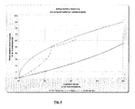
- Fig. 4 the effectiveness of different charging strategies is shown.
- the ordinate records the amount by which the total capacity of the battery (as for all cell blocks in total) increases, the abscissa shows the energy supplied as a percentage of the nominal capacity.
- a first charging strategy the block with the lowest voltage is charged until it has reached the voltage of the block with previously maximum voltage.
- This charging strategy corresponds to the curve at which the available battery capacity increases the least, thus the charging efficiency is the lowest.
- the lowest voltage block is charged until it reaches a voltage equal to the average of the voltages of the other blocks.
- the third charging strategy is the adaptive charging strategy according to the present embodiment, in which the block having the lowest voltage is charged for a predetermined time.
- the third charging strategy is like out Fig. 4
- the gain in available battery capacity is greatest, so it corresponds to the curve with the largest gain in available battery capacity.
- the amount of energy supplied is largely or entirely reflected in the increase in the total capacity of the multi-block cell. It is z. For example, suppose the cell consists of twenty blocks and has a nominal voltage of 200 volts (i.e., 10 volts per cell block). Further, the average voltage per cell block is 7 volts, that of the lowest block is 6.5 volts, that of the second lowest block is 6.7 volts, and that of the highest voltage block is 7.5 volts.
- the charging strategy "charging to the maximum”, on the other hand, is only on an external power supply of 1/2 * delta_p * K equal to the charging strategy of the embodiment of the invention.
- the charge of the lowest voltage block is not for a predetermined time, but up to a voltage which exceeds the voltage of the second least significant voltage block by a certain predefined value.
- This may be, for example, a certain fraction of the voltage value of the second lowest voltage block or a predetermined voltage difference value.
- There may also be provided a look-up table that defines the voltage difference value to be charged depending on the voltage value of, for example, the second lowest voltage block or another block (eg, the highest voltage block), also in this way An "excess" loading of the block with the lowest voltage can be largely avoided.
- a plurality of cell blocks may be commonly charged, for example the block with the lowest voltage and that with the second lowest voltage. This may be done, for example, by charging the multiple cell blocks all for the same (predetermined) charging time.
- the multiple cell blocks may also be loaded for a different (predetermined) charging time, where z. B. the cell block is charged with the lowest voltage for the longest (predetermined) time, with the second lowest voltage for the second longest predetermined time, etc.
- a lookup table which specifies at what voltage difference to the cell block the highest voltage for which time period is to be loaded.
- look-up table can also be provided if only one cell block is loaded at the same time.
- the look-up table may then predetermine the predetermined time depending on the voltage difference between the lowest voltage block and the highest voltage block.
- the predetermined time may also be set depending on the voltage difference between the lowest voltage block and the second lowest voltage block. The latter is particularly advantageous, because then the charging time specifications can be selected specifically so that an excess charging is avoided if possible, for example, by a larger voltage difference, a larger charging time is provided at a smaller voltage difference, however, a smaller predetermined charging time.
- the cell block is charged with the lowest voltage until its voltage corresponds to the voltage of the cell block with the second lowest voltage.
- these two Zelienblöcke are then charged together, until their cell voltage corresponds to that of the cell block with the next higher voltage.
- these three cell blocks, which now have the same voltage are then charged together, until they have reached the voltage of the block with the next higher voltage. This can then be repeated in the same way, so that after each loading step another cell block is added to the cell blocks which can be loaded together.
- Fig. 5A illustrates the initial state
- the cell block dispersion is +/- 20%
- cell block 4 has the minimum state of charge with 50.97% of all ten cell blocks.
- Fig. 5B now illustrates the next higher charged cell block # 9 with a charge level of 53.98%. Now, cell block # 4 is loaded to the level of cell block # 9.
- Fig. 5C illustrates the result of this charging process and shows the next higher charged cell block # 3 with a level of 56.34%. Now, the cell blocks No. 4 and No. 9 are loaded together to the level of the cell block No. 3.
- Fig. 5D which also illustrates the next higher cell block with a level of 64.21%.
- Fig. 5E reached state in which the cell blocks Nos. 1, 3, 4 and 9 have reached the level of 64.21% and then raised in a following step to the level of cell block No. 7 (65.7%).
- the process can be continued in the same way by further charging steps until all cell blocks are at the same charge level.
- the measuring device measures the temperature of the cell blocks. It can then be aborted, for example, when a predetermined temperature value is exceeded, in order not to damage the cell block.
- the charging time of a cell block may, according to a further embodiment, depend not only on one parameter but also on several parameters. Thus, the temperature or other parameters can be included in the decision as to whether and how long a cell block is loaded.
- charging of the entire high-voltage memory is distributed among the individual cell blocks of the high-voltage memory by being selectively driven and charged for a predetermined or different times, thereby charging the high-voltage memory as a whole.
- the "intelligent" charge of the high-voltage memory is thus based on the selective “switching through” of the charging voltage supplied by the solar module to the individual cell blocks, as well as on the measurement and consideration of one or more parameters by the control logic of the device.
- a parameter measured by the measuring device for the respective cell blocks may be the introduced energy for that cell block. Based on the introduced and the expected energy to be decided on the charging process for this cell block.
- the parameter measured by the measuring device for the plurality of cell blocks comprises the status of health (SOH) of the respective cell block, and based on this parameter, more charging time is provided for batteries with poor status of health.
- SOH is a known parameter that characterizes the "health" of a battery. The inclusion of this parameter in the control of the charging process refines its adaptability to the current conditions in the high-voltage storage.
- the loader may monitor or remember the various SOH values of the individual memory areas / cells / blocks and treat more needy areas separately, i. load more often or longer.
- the parameter measured by the measuring device comprises the "Status of Charge” SOC and based on this, the charging process for this cell is decided.
- the SOC is a known parameter that characterizes the state of charge of the battery. The inclusion of this parameter in the control of the charging refines its adaptability to the current conditions in the high-voltage storage.
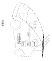
- Fig. 3 schematically shows a vehicle with a solar-powered charging device according to an embodiment of the invention.
- Solar energy hits the solar panel and is converted into electrical energy.
- she then encounters a module that decides on the operating strategy of the supplied solar energy.
- This module corresponds to the control device of the preceding embodiments. It decides in the embodiment of Fig. 3 not only through the switching of the charging current via the drive module SMC to the single cells, but can also distribute the solar charging current to other consumers or as in Fig. 3 shown in a 12 V distribution board. Shown here are as other consumers such as mobile phone and navigation system, other consumers are also conceivable.
- the described embodiments describe a solar-based charging device, in particular for hybrid vehicles, which has various advantages over the prior art.
- the charging voltage may not come from a solar module, but rather from another voltage source (eg, a DC source or a rectified AC source).
- another voltage source eg, a DC source or a rectified AC source.
- the described mechanisms regarding the measurement of parameters of the cell blocks as well as the control logic for switching the charging voltage can be applied in an analogous manner. It then results in an analogous manner, the advantages described in terms of the adaptivity of the charging process as well as the charge balancing.
Landscapes
- Engineering & Computer Science (AREA)
- Power Engineering (AREA)
- Transportation (AREA)
- Mechanical Engineering (AREA)
- Life Sciences & Earth Sciences (AREA)
- Sustainable Development (AREA)
- Sustainable Energy (AREA)
- Manufacturing & Machinery (AREA)
- Chemical & Material Sciences (AREA)
- Chemical Kinetics & Catalysis (AREA)
- Electrochemistry (AREA)
- General Chemical & Material Sciences (AREA)
- Charge And Discharge Circuits For Batteries Or The Like (AREA)
- Electric Propulsion And Braking For Vehicles (AREA)
- Secondary Cells (AREA)
Applications Claiming Priority (1)
| Application Number | Priority Date | Filing Date | Title |
|---|---|---|---|
| DE102009027685A DE102009027685A1 (de) | 2009-07-14 | 2009-07-14 | Solargestützte Batterieladevorrichtung |
Publications (2)
| Publication Number | Publication Date |
|---|---|
| EP2276100A2 true EP2276100A2 (fr) | 2011-01-19 |
| EP2276100A3 EP2276100A3 (fr) | 2012-08-15 |
Family
ID=43014392
Family Applications (1)
| Application Number | Title | Priority Date | Filing Date |
|---|---|---|---|
| EP10169569A Withdrawn EP2276100A3 (fr) | 2009-07-14 | 2010-07-14 | Dispositif de chargement de batterie solaire |
Country Status (2)
| Country | Link |
|---|---|
| EP (1) | EP2276100A3 (fr) |
| DE (1) | DE102009027685A1 (fr) |
Cited By (7)
| Publication number | Priority date | Publication date | Assignee | Title |
|---|---|---|---|---|
| WO2012127270A1 (fr) * | 2011-03-23 | 2012-09-27 | Indian Institute Of Technology Bombay | Chargement d'une batterie basé sur un convertisseur cc-cc à condensateur commuté alimenté par un ensemble photovoltaïque pour batteries au lithium-ion |
| EP2759037A4 (fr) * | 2011-09-20 | 2015-07-08 | Sony Corp | Dispositif de charge de batterie secondaire, procédé de charge dans un dispositif de charge de batterie secondaire, générateur photovoltaïque, procédé de génération électrique dans un générateur photovoltaïque, système de batterie secondaire chargé de manière photovoltaïque, dispositif électronique et véhicule électrique |
| DE102015000593A1 (de) * | 2015-01-16 | 2016-07-21 | Audi Ag | Hochspannungsbatterie für ein Kraftfahrzeug und Kraftfahrzeug |
| CN107244239A (zh) * | 2017-08-04 | 2017-10-13 | 聊城中通轻型客车有限公司 | 一种电动汽车太阳能充电系统及控制方法 |
| NL2019694B1 (en) * | 2017-10-10 | 2019-04-19 | Innolex Eng Bv | Method and apparatus to individually control batteries, connected in series, inside a solar power station |
| US11431188B1 (en) * | 2016-12-29 | 2022-08-30 | Hive Energy Systems Llc | System for highly efficient transfer of energy produced by Photovoltaic panels into batteries for storage |
| DE102021107959A1 (de) | 2021-03-30 | 2022-10-06 | Bayerische Motoren Werke Aktiengesellschaft | Ladevorrichtung sowie Verfahren zum Betreiben einer Ladevorrichtung zum solargestützten Laden eines Kraftfahrzeugs |
Families Citing this family (10)
| Publication number | Priority date | Publication date | Assignee | Title |
|---|---|---|---|---|
| DE102011079242A1 (de) | 2011-07-15 | 2013-01-17 | Bayerische Motoren Werke Aktiengesellschaft | Ladestation zum Aufladen eines Elektrofahrzeugs mit einem Zwischenspeicher zum Speichern von seitens einer Photovoltaikanlage gelieferter Energie |
| DE102011107269B4 (de) | 2011-07-15 | 2021-06-02 | Volkswagen Aktiengesellschaft | Verfahren und Vorrichtung zum solargestützten Laden einer Batterie und Ladeeinrichtung |
| DE102011119905A1 (de) | 2011-11-30 | 2013-06-06 | Volkswagen Aktiengesellschaft | Elektrische Energieversorgung eines Elektro- oder Hybridfahrzeuges |
| DE102011119904B4 (de) | 2011-11-30 | 2023-05-25 | Volkswagen Aktiengesellschaft | Elektrische Energieversorgung eines Elektro- oder Hybridfahrzeuges |
| DE102011121250A1 (de) | 2011-12-15 | 2013-06-20 | Volkswagen Aktiengesellschaft | Verfahren zum Betreiben eines Ladungsspeichers eines Elektrofahrzeugs |
| DE102014108601B4 (de) | 2013-06-28 | 2026-05-13 | Sma Solar Technology Ag | Verfahren zum Anschließen mehrerer Batterieeinheiten an einen zweipoligen Eingang eines bidirektionalen Batteriewandlers sowie bidirektionaler Batteriewandler und Photovoltaikwechselrichter |
| DE102015219665A1 (de) * | 2015-10-12 | 2017-04-13 | Audi Ag | Verfahren zum Laden einer Batterie eines Kraftfahrzeugs und Kraftfahrzeug |
| DE102015224092B4 (de) | 2015-12-02 | 2021-05-12 | Volkswagen Aktiengesellschaft | Elektrisches Hochvoltsystem und Verfahren zum Laden einer Hochvoltbatterie eines elektrischen Hochvoltsystems |
| DE102015224842A1 (de) | 2015-12-10 | 2017-06-14 | Volkswagen Aktiengesellschaft | Elektrisches Spannungsnetzwerk und Verfahren zum Verteilen von elektrischer Energie in einem elektrischen Spannungsnetzwerk |
| DE102021107958A1 (de) | 2021-03-30 | 2022-10-06 | Bayerische Motoren Werke Aktiengesellschaft | Kraftfahrzeug mit einer Antriebsbatterie zum solargestützten Laden sowie Verfahren zum solargestützten Laden einer Antriebsbatterie |
Citations (1)
| Publication number | Priority date | Publication date | Assignee | Title |
|---|---|---|---|---|
| US20060214636A1 (en) * | 2005-03-04 | 2006-09-28 | Yazaki Corporation | Method and apparatus for equalizing secondary cells |
Family Cites Families (9)
| Publication number | Priority date | Publication date | Assignee | Title |
|---|---|---|---|---|
| FR2735624B1 (fr) * | 1995-06-16 | 1997-09-05 | Smh Management Services Ag | Chargeur pour accumulateur d'energie electrique |
| JP3767422B2 (ja) * | 2001-06-01 | 2006-04-19 | 日産自動車株式会社 | 充電方法および充電装置 |
| JP4079871B2 (ja) * | 2003-12-17 | 2008-04-23 | 三洋電機株式会社 | パック電池 |
| DE102005045107A1 (de) * | 2005-09-21 | 2007-03-29 | Zentrum für Sonnenenergie- und Wasserstoff-Forschung Baden-Württemberg | Ladeverfahren zur Verlängerung der Lebensdauer von Batterien und Vorrichtung zur Durchführung desselben |
| JP5401003B2 (ja) * | 2006-01-27 | 2014-01-29 | シャープ株式会社 | 太陽光発電システム |
| US20080100258A1 (en) * | 2006-08-23 | 2008-05-01 | Ward Thomas A | Hybrid vehicle with adjustable modular solar panel to increase charge generation |
| JP5248764B2 (ja) * | 2006-11-02 | 2013-07-31 | パナソニック株式会社 | 蓄電素子の異常検出装置、蓄電素子の異常検出方法及びその異常検出プログラム |
| US7872443B2 (en) * | 2007-02-23 | 2011-01-18 | Ward Thomas A | Current limiting parallel battery charging system to enable plug-in or solar power to supplement regenerative braking in hybrid or electric vehicle |
| JP4686768B2 (ja) * | 2007-12-06 | 2011-05-25 | 本田技研工業株式会社 | 充電制御装置及びセル電圧均等化装置 |
-
2009
- 2009-07-14 DE DE102009027685A patent/DE102009027685A1/de not_active Withdrawn
-
2010
- 2010-07-14 EP EP10169569A patent/EP2276100A3/fr not_active Withdrawn
Patent Citations (1)
| Publication number | Priority date | Publication date | Assignee | Title |
|---|---|---|---|---|
| US20060214636A1 (en) * | 2005-03-04 | 2006-09-28 | Yazaki Corporation | Method and apparatus for equalizing secondary cells |
Cited By (9)
| Publication number | Priority date | Publication date | Assignee | Title |
|---|---|---|---|---|
| WO2012127270A1 (fr) * | 2011-03-23 | 2012-09-27 | Indian Institute Of Technology Bombay | Chargement d'une batterie basé sur un convertisseur cc-cc à condensateur commuté alimenté par un ensemble photovoltaïque pour batteries au lithium-ion |
| EP2759037A4 (fr) * | 2011-09-20 | 2015-07-08 | Sony Corp | Dispositif de charge de batterie secondaire, procédé de charge dans un dispositif de charge de batterie secondaire, générateur photovoltaïque, procédé de génération électrique dans un générateur photovoltaïque, système de batterie secondaire chargé de manière photovoltaïque, dispositif électronique et véhicule électrique |
| DE102015000593A1 (de) * | 2015-01-16 | 2016-07-21 | Audi Ag | Hochspannungsbatterie für ein Kraftfahrzeug und Kraftfahrzeug |
| US10442299B2 (en) | 2015-01-16 | 2019-10-15 | Audi Ag | High-voltage battery for a motor vehicle, and motor vehicle |
| US11431188B1 (en) * | 2016-12-29 | 2022-08-30 | Hive Energy Systems Llc | System for highly efficient transfer of energy produced by Photovoltaic panels into batteries for storage |
| CN107244239A (zh) * | 2017-08-04 | 2017-10-13 | 聊城中通轻型客车有限公司 | 一种电动汽车太阳能充电系统及控制方法 |
| CN107244239B (zh) * | 2017-08-04 | 2023-09-08 | 中通客车股份有限公司 | 一种电动汽车太阳能充电系统及控制方法 |
| NL2019694B1 (en) * | 2017-10-10 | 2019-04-19 | Innolex Eng Bv | Method and apparatus to individually control batteries, connected in series, inside a solar power station |
| DE102021107959A1 (de) | 2021-03-30 | 2022-10-06 | Bayerische Motoren Werke Aktiengesellschaft | Ladevorrichtung sowie Verfahren zum Betreiben einer Ladevorrichtung zum solargestützten Laden eines Kraftfahrzeugs |
Also Published As
| Publication number | Publication date |
|---|---|
| EP2276100A3 (fr) | 2012-08-15 |
| DE102009027685A1 (de) | 2011-01-20 |
Similar Documents
| Publication | Publication Date | Title |
|---|---|---|
| DE102009027685A1 (de) | Solargestützte Batterieladevorrichtung | |
| EP2514063B1 (fr) | Système d'accumulation d'énergie et procédé pour le faire fonctionner | |
| EP3137335B1 (fr) | Commande pour véhicule à entraînement électrique, véhicule à entraînement électrique comportant une commande et procédé | |
| EP1325542B1 (fr) | Procede de regulation de la tension d'un generateur dans une automobile | |
| DE102013225097B4 (de) | Energiemanagementverfahren zum Betreiben eines elektrischen Bordnetzes eines Kraftfahrzeuges und Kraftfahrzeug | |
| DE102021206199A1 (de) | Batteriesteuereinheit und Batteriesystem | |
| DE102011002264A1 (de) | Leistungsversorgungseinheit mit einer Vielzahl von Akkumulatoren | |
| DE102004052457A1 (de) | Kraftfahrzeug-Stromversorgungssystem zur Sicherung der Stabilität der Aufladung von Speicherbatterien | |
| DE10157859A1 (de) | Pseudo-parallele Ladesysteme und -verfahren | |
| DE112011100550T5 (de) | Zellkapazitätsjustiervorrichtung | |
| EP1829185B1 (fr) | Circuit de redistribution de charge | |
| EP3470259B1 (fr) | Système d'accumulateurs d'énergie doté d'une pluralité d'accumulateurs d'énergie couplés en parallèle et procédé de fonctionnement d'un système d'accumulateurs d'énergie | |
| DE102013204885A1 (de) | Verfahren zur Reduzierung des Gesamtladungsverlusts von Batterien | |
| EP3720733B1 (fr) | Procédé de commande d'une installation électrique d'un véhicule à moteur à entraînement électrique, dotée de plusieurs batteries et installation électrique d'un véhicule à entraînement électrique | |
| DE102022117000A1 (de) | Batterielademanager | |
| EP1588448B1 (fr) | Systeme de pile a combustible et procede pour faire fonctionner une systeme de pile a combustible | |
| EP1941594B1 (fr) | Procede de charge pour augmenter la longevite de batteries et dispositif pour le realiser | |
| DE10312591B4 (de) | Ladeverfahren für eine wiederaufladbare Batterie | |
| DE102005046342B4 (de) | Verfahren zur Regelung einer Ausgangsspannung eines Generators | |
| DE102014108601B4 (de) | Verfahren zum Anschließen mehrerer Batterieeinheiten an einen zweipoligen Eingang eines bidirektionalen Batteriewandlers sowie bidirektionaler Batteriewandler und Photovoltaikwechselrichter | |
| DE102015006280A1 (de) | Fahrzeug und elektrische Antriebsvorrichtung für ein Fahrzeug | |
| DE102010017439A1 (de) | Schaltungsanordnung und Verfahren zum Ausgleich von unterschiedlichen Ladezuständen von Zellen eines Energiespeichers | |
| DE102015222264A1 (de) | Verfahren und vorrichtung für das energiemanagement eines energiespeichers zur vermeidung von mikrozyklen | |
| DE102022101927A1 (de) | Angleichen von Ladezuständen von Batteriemodulen eines Elektrofahrzeugs | |
| DE102012007324B4 (de) | Energiespeicheranordnung |
Legal Events
| Date | Code | Title | Description |
|---|---|---|---|
| PUAI | Public reference made under article 153(3) epc to a published international application that has entered the european phase |
Free format text: ORIGINAL CODE: 0009012 |
|
| AK | Designated contracting states |
Kind code of ref document: A2 Designated state(s): AL AT BE BG CH CY CZ DE DK EE ES FI FR GB GR HR HU IE IS IT LI LT LU LV MC MK MT NL NO PL PT RO SE SI SK SM TR |
|
| AX | Request for extension of the european patent |
Extension state: BA ME RS |
|
| PUAL | Search report despatched |
Free format text: ORIGINAL CODE: 0009013 |
|
| AK | Designated contracting states |
Kind code of ref document: A3 Designated state(s): AL AT BE BG CH CY CZ DE DK EE ES FI FR GB GR HR HU IE IS IT LI LT LU LV MC MK MT NL NO PL PT RO SE SI SK SM TR |
|
| AX | Request for extension of the european patent |
Extension state: BA ME RS |
|
| RIC1 | Information provided on ipc code assigned before grant |
Ipc: H02J 7/35 20060101ALI20120710BHEP Ipc: H01M 10/44 20060101AFI20120710BHEP Ipc: H01M 10/46 20060101ALI20120710BHEP |
|
| 17P | Request for examination filed |
Effective date: 20130215 |
|
| RIC1 | Information provided on ipc code assigned before grant |
Ipc: H01M 10/44 20060101AFI20140211BHEP Ipc: H02J 7/35 20060101ALI20140211BHEP Ipc: H01M 10/46 20060101ALI20140211BHEP Ipc: B60L 8/00 20060101ALI20140211BHEP Ipc: B60L 11/18 20060101ALI20140211BHEP |
|
| 17Q | First examination report despatched |
Effective date: 20140225 |
|
| STAA | Information on the status of an ep patent application or granted ep patent |
Free format text: STATUS: THE APPLICATION IS DEEMED TO BE WITHDRAWN |
|
| 18D | Application deemed to be withdrawn |
Effective date: 20140708 |