EP2276134A1 - Passe-fil - Google Patents
Passe-fil Download PDFInfo
- Publication number
- EP2276134A1 EP2276134A1 EP08874548A EP08874548A EP2276134A1 EP 2276134 A1 EP2276134 A1 EP 2276134A1 EP 08874548 A EP08874548 A EP 08874548A EP 08874548 A EP08874548 A EP 08874548A EP 2276134 A1 EP2276134 A1 EP 2276134A1
- Authority
- EP
- European Patent Office
- Prior art keywords
- annular coupling
- inner tube
- grommet
- coupling section
- peripheral surface
- Prior art date
- Legal status (The legal status is an assumption and is not a legal conclusion. Google has not performed a legal analysis and makes no representation as to the accuracy of the status listed.)
- Withdrawn
Links
Images



Classifications
-
- B—PERFORMING OPERATIONS; TRANSPORTING
- B60—VEHICLES IN GENERAL
- B60R—VEHICLES, VEHICLE FITTINGS, OR VEHICLE PARTS, NOT OTHERWISE PROVIDED FOR
- B60R16/00—Electric or fluid circuits specially adapted for vehicles and not otherwise provided for; Arrangement of elements of electric or fluid circuits specially adapted for vehicles and not otherwise provided for
- B60R16/02—Electric or fluid circuits specially adapted for vehicles and not otherwise provided for; Arrangement of elements of electric or fluid circuits specially adapted for vehicles and not otherwise provided for electric constitutive elements
- B60R16/0207—Wire harnesses
- B60R16/0215—Protecting, fastening and routing means therefor
- B60R16/0222—Grommets
-
- B—PERFORMING OPERATIONS; TRANSPORTING
- B60—VEHICLES IN GENERAL
- B60R—VEHICLES, VEHICLE FITTINGS, OR VEHICLE PARTS, NOT OTHERWISE PROVIDED FOR
- B60R16/00—Electric or fluid circuits specially adapted for vehicles and not otherwise provided for; Arrangement of elements of electric or fluid circuits specially adapted for vehicles and not otherwise provided for
- B60R16/02—Electric or fluid circuits specially adapted for vehicles and not otherwise provided for; Arrangement of elements of electric or fluid circuits specially adapted for vehicles and not otherwise provided for electric constitutive elements
- B60R16/023—Electric or fluid circuits specially adapted for vehicles and not otherwise provided for; Arrangement of elements of electric or fluid circuits specially adapted for vehicles and not otherwise provided for electric constitutive elements for transmission of signals between vehicle parts or subsystems
-
- H—ELECTRICITY
- H01—ELECTRIC ELEMENTS
- H01B—CABLES; CONDUCTORS; INSULATORS; SELECTION OF MATERIALS FOR THEIR CONDUCTIVE, INSULATING OR DIELECTRIC PROPERTIES
- H01B17/00—Insulators or insulating bodies characterised by their form
- H01B17/56—Insulating bodies
- H01B17/58—Tubes, sleeves, beads, or bobbins through which the conductor passes
- H01B17/583—Grommets; Bushings
-
- H—ELECTRICITY
- H02—GENERATION; CONVERSION OR DISTRIBUTION OF ELECTRIC POWER
- H02G—INSTALLATION OF ELECTRIC CABLES OR LINES, OR OF COMBINED OPTICAL AND ELECTRIC CABLES OR LINES
- H02G3/00—Installations of electric cables or lines or protective tubing therefor in or on buildings, equivalent structures or vehicles
- H02G3/02—Details
- H02G3/04—Protective tubing or conduits, e.g. cable ladders or cable troughs
- H02G3/0462—Tubings, i.e. having a closed section
- H02G3/0468—Corrugated
-
- H—ELECTRICITY
- H02—GENERATION; CONVERSION OR DISTRIBUTION OF ELECTRIC POWER
- H02G—INSTALLATION OF ELECTRIC CABLES OR LINES, OR OF COMBINED OPTICAL AND ELECTRIC CABLES OR LINES
- H02G3/00—Installations of electric cables or lines or protective tubing therefor in or on buildings, equivalent structures or vehicles
- H02G3/22—Installations of cables or lines through walls, floors or ceilings, e.g. into buildings
Definitions
- an object of the present invention is to provide a grommet that can enhance a waterproofing function by preventing a clearance from being caused in a connecting part between a smaller diameter tubular section of the grommet and a wire harness that passes the grommet in a close contact manner, and in particular to provide a grommet that can prevent a clearance from being caused in a connecting part between the grommet and a wire harness and to provide a grommet of which a vehicle body latch recess is not deformed, thereby maintaining a good sealing function, even if a wire harness that passes the grommet is bent sharply.
- the present invention is directed to a grommet that is mounted on a wire harness to be inserted into a through-hole in a vehicle body, is engaged with a vehicle body, and is made of an elastic material.
- the grommet includes: an inner tube for passing electrical cables in the wire harness in a close contact manner; an annular coupling section protruding an outer peripheral surface of the inner tube; and an outer tube continued to an outer peripheral surface of the annular coupling section and disposed coaxially with the inner tube.
- the outer tube is adapted to couple the annular coupling section to a larger thickness portion of the outer tube and to couple a reducing diameter slant wall section to the larger thickness portion.
- the outer tube is provided in an outer peripheral surface at a boundary area between the larger thickness portion and the slant wall section with a vehicle body latch recess in an annular manner.
- the annular coupling section is formed into a smaller thickness.
- the annular coupling section is bent in a V-shaped configuration from an inner peripheral end coupled to the outer peripheral surface of the inner tube to an outer peripheral end coupled to an inner peripheral surface of the outer tube.
- a projecting direction of the V-shaped configuration of the annular coupling section is opposite in direction to an extension of the slant wall section of the outer tube. If the annular coupling section protrudes toward the slant wall section, when the grommet is inserted into the through-hole in the vehicle body panel, the slant wall section is deflected inward and the annular coupling section that protrudes inward interferes with the deflection of the slant wall section. This will affect reduction in inserting force of the grommet.
- the V-shaped configuration of the annular coupling section is set to be an angle of 40 to 70 (forty to seventy) degrees.
- a length of the annular coupling section is set to be 1.5 to 4 (one and a half to four) times of a radial distance between an inner peripheral surface of the inner tube and an outer peripheral surface of the outer tube.
- a thickness of the annular coupling section is set to be less than thicknesses of the inner and outer tubes.
- the annular coupling section can increase an amount of absorbing the bending, so that transmission of the bending to the outer tube is cut off. If the annular coupling section has the smaller thickness, the annular coupling section can exert an absorbing action of the bending easily.
- the grommet can respond to the varying sizes in diameter of the wire harness merely by altering the bending angle of the annular coupling section, thereby permitting the tape to be wound around the inner tube, with the inner tube closely contacting with the wire harness. Even if the inner tube is bent on account of the bending of the wire harness, the annular coupling section is contracted or expanded so as to follow the bending of the wire harness and the deformation of the inner tube can be absorbed in the annular coupling section before the bending of the inner tube is transmitted to the outer tube.
- the vehicle body latch recess provided in the outer peripheral surface of the outer tube from being deformed so as to maintain the recess in the circular shape and to prevent the recess from floating up.
- the vehicle body latch recess can contact with the peripheral edge around the through-hole in the vehicle body panel without shifting the recess from the through-hole. This can enhance the sealing effect and prevent the water leakage.
- the annular coupling section protrudes from the outer peripheral surface of a longitudinal intermediate part between a pushing-in side and a drawing-out side of both ends of the inner tube.
- the larger thickness portion of the outer tube is continued to the outer peripheral end of the annular coupling section.
- An inner peripheral surface at a smaller diameter end side of the slant wall section of the outer tube is separated through a given clearance from the outer peripheral surface of the inner tube.
- a drawing-out side of the inner tube protrudes outward from the slant wall section.
- the inner tube through which the wire harness passes in the close contact manner is separated at the drawing-out side of the wire harness through a great clearance from the outer tube provided with the vehicle body latch recess.
- the separated type grommet even if the wire harness that is drawn out from the grommet and is arranged in the passenger room is bent sharply by an angle of 90 degrees or so to bend the inner tube, it is possible to prevent the bending of the inner tube from being transmitted to the outer tube directly.
- the inner tube of the above grommet through which the wire harness passes in the close contact manner is not divided into half cylinders but the inner tube is formed into an integrated cylinder, it is possible for the inner tube to closely contact with the whole outer peripheral surface of the wire harness merely by increasing or decreasing the diameter of the inner tube in accordance with the varying sizes in diameter of the wire harness, thereby enhancing the sealing function of the connecting part between the grommet and the wire harness.
- the grommet of the present invention is either the separated type grommet or the coupled type grommet
- the stepped longitudinal projecting ribs protrude from the outer peripheral surface of the slant wall section and are separated apart from one another in the peripheral direction, so that the contact area between the slant wall section and the through-hole can be reduced to lower the inserting force.
- the grommet can be inserted into the through-hole in the vehicle body panel by the one-motion operation of pushing the grommet from one side, thereby decreasing the inserting force.
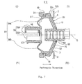
- a grommet 1 is mounted on a wire harness W/H arranged from an engine room X in a motor vehicle via a through-hole 3 in a vehicle body panel 2 to a passenger room Y.
- the grommet 1 is engaged with a peripheral edge around the through-hole 3 to be attached to the vehicle body.
- the grommet 1 is a one-motion type grommet that is inserted into the through-hole 3 from an engine room X so as to be attached to the vehicle body.
- the one end of the grommet 1 defines a pushing-in side P1 while the other end defines a drawing-out side P2.
- the grommet 1 is molded from rubber or elastomer.
- the outer tube 8 is coaxial with the inner tube 5 and is disposed through a space on an intermediate part of the inner tube 5 in its longitudinal direction.
- the inner tube 5 protrudes from opposite ends of the outer tube 8 at the pushing-in side P1 and the drawing-out side P2 in the longitudinal direction.
- the outer tube 8 extends to the drawing-out side P2 from a connecting part between the outer tube 8 and an outer peripheral surface of the annular coupling section 6.
- a slant wall section 11 is continued to a larger thickness portion 9 provided on the connecting part and extends to the drawing-out side P2 to reduce a diameter of the section 11 in the axial direction.
- An annular clearance S ( Figure 3 ) is defined between an inner peripheral surface of the drawing-out distal end side tubular portion 12 and the outer peripheral surface 5a of the inner tube 5 to separate the portion 12 apart from the inner tube 5. That is, a smaller diameter end of the outer tube 8 surrounds the outer peripheral surface of the inner tube 5 through the annular clearance S and the drawing-out end 5P2 protrudes outward from the outer tube 8.
- a radial distance d1 of the annular clearance S is set to be 1/2 to 3/2 (one-half to three-halves) of a radius d2 of the inner tube 5. It is preferable in the present embodiment that the radial distance d1 is 3/4 (three quarters) of the radius d2.
- a length L1 of the drawing-out distal end side tubular portion 12 that extends through the annular clearance S in parallel to the outer peripheral surface 5a of the inner tube 5 may be altered in accordance with a size of the grommet 1. It is preferable in the present embodiment that the length L1 is 5 to 15 mm (five to fifteen millimeters) .
- a projecting direction of the V-shaped configuration of the annular coupling section 6 is opposite in direction to an extension of the slant wall section 11 of the outer tube 8, that is, the V-shaped configuration is directed to the pushing-in side P1.
- An angle ⁇ 1 (theta one) of the V-shaped configuration of the annular connecting section 6 is set to be 40 to 70 (forty to seventy) degrees. In the first embodiment, the angle ⁇ 1 (theta one) is 60 (sixty) degrees.
- a length from the inner peripheral end 6b of the annular coupling section 6 to the outer peripheral end 6a is set to be 1.5 to 4 (one and a half to four) times of a radial distance between an inner peripheral surface of the inner tube 5 and an outer peripheral surface of the outer tube 8. In the first embodiment, the length is 2.5 (two and a half) times of the radial distance.
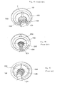
- annular coupling section 6 is not bent in the V-shaped configuration at two opposite positions in a diametrical direction of the section 6 to form flat surfaces 6e and 6f.
- the flat surfaces 6e and 6f are provided with through-apertures 31 and 32 through which the opener cable and feed water hose pass.
- a thickness t3 ( Figure 3 ) of the annular coupling section 6 is set to be substantially equal to or less than a thickness t4 ( Figure 3 ) of the inner tube 5 so as to be deflectable.
- An angle ⁇ 2 (theta two) of the annular coupling section 6 that is slant coupled to the outer peripheral surface 5a of the inner tube 5 is set to be 20 to 30 (twenty to thirty) degrees.
- the inner tube 5 and outer tube 8 are not interconnected to each other directly in the radial direction but interconnected to each other through the V-shaped annular coupling section 6.
- a sound-insulating space B ( Figure 3 ) is defined among the pushing rib 18, the inner tube 5, the annular coupling section 6, and the outer tube 8.
- the pushing rib 18 protrudes slightly slant in its outer diametrical direction.
- the projecting end 18a is opposed to the smaller diameter end of the slant wall section 11 continued to the drawing-out distal end side tubular portion 12.
- the drawing-out distal end side tubular portion 12 is provided with a stopper projection 12a, which protrudes inward from the slant wall section 11, at a side of the slant wall section 11 with which the pushing rib 18 contacts.
- the slant wall section 11 is provided with an annular shallow recess in an inner surface from an outer diameter side, with which the projecting end 18a of the pushing rib 18 contacts, to the curved portion 11c.
- the slant wall section 11 is provided with a smaller thickness portion 19 ( Figure 5 ) having a smaller thickness t6 ( Figure 3 ). Since the slant wall section 11 is provided with the smaller thickness portion 19 from the curved portion 11c to the smaller diameter side, the smaller thickness portion 19 serves as a stress absorbing portion when the drawing-out distal end side tubular portion 12 is deformed on account of the bending of the wire harness.
- the larger thickness portion 9 of the outer tube 8 protrudes slightly toward the pushing-in side P1 from the connecting part between the larger thickness portion 9 and an outer peripheral end 6a of the annular coupling section 6.
- a pushing-in side distal end surface 9a defines an orthogonal surface to an axis 0 of the inner tube 5.
- the annular vehicle body latch recess 10 is provided on a boundary area between the larger thickness portion 9 and the slant wall section 11.
- a distal end of a drawing-out side surface 10b that stands up from a bottom surface 10a of the vehicle body latch recess 10 is continued to a larger diameter end 11a of the slant wall section 11.
- a smaller diameter end 11b of the slant wall section 11 is continued to the drawing-out distal end side tubular portion 12.
- a curved portion 11c is provided between the larger diameter end 11a of the slant wall 11 and the smaller diameter end 11b so as to change an inclination angle of the outer peripheral surface of the slant wall section 11.
- An inclination angle at the smaller diameter end side with respect to the curved portion 11c is set to be large while an inclination angle at the larger diameter end side with respect to the curved portion 11c is set to be small.
- the slant wall section 11 is provided on the outer peripheral surface that changes the inclination angle with axially stepped projecting ribs 15 that extend from the larger diameter end 11a of the distal end of the drawing-out side surface 10b on the vehicle body latch recess 10 to the smaller diameter end 11b and are spaced apart from one another in the peripheral direction. Since these projecting ribs 15 have the same widths in the peripheral direction, the projecting ribs 15 that extend radially from the smaller diameter end to the larger diameter end have narrow distances between the adjacent ribs 15 at the smaller diameter end side in the peripheral direction and wide distances between the adjacent ribs 15 at the larger diameter end side.
- the inner peripheral surface of the outer tube 8 from the larger thickness portion 9 to the curved portion 11c of the slant wall section 11, that is, from the larger thickness portion 9 to a larger diameter side end 11e defines a parallel surface 11h in parallel to the axial direction 0.
- a thickness t1 of a portion 11d from the curved portion 11c to the drawing-out distal end side tubular portion 12 is set to be small.
- a thickness t2 of the drawing-out distal end side tubular portion 12 is set to be larger than the thickness t1.
- each projecting rib 15 that extends on the outer peripheral surface of the slant wall section 11 from the smaller diameter end of the slant wall section 11 to the larger diameter end is provided in an inner peripheral surface with a recess 15h that extends through a whole length of the projecting rib 15.
- the slant wall section 11 is provided with axial grooves 15k and 15i on an outer surface at proximal ends of each projecting rib 15 and on each central parts between the adjacent projecting ribs 15, thereby facilitating to deflect the slant wall section 11.
- each projecting rib 15 provided on its larger diameter side of the slant wall section 11 is provided with a slant surface 15c that inclines the top surface 15a of the projecting rib 15 downward to the drawing-out side surface 10b.
- Both side surfaces 15d and 15e of each projecting rib 15 at its distal end side across the slant surface 15c define slant surfaces 15f and 15g that approach to each other. That is, each projecting rib 15 is provided on its larger diameter end with the slant surfaces 15, 15f, and 15g that are cut at three sides.
- each projecting rib 15 is cut at the three sides to form round corners and to eliminate edges, the projecting ribs 15 are not caught by the peripheral edge around the through-hole 3 in the vehicle body panel 2 when the peripheral edge around the through-hole 3 drops down into the vehicle body latch recess 10.
- the opener cable and feed water hose penetrate the grommet 1.
- the slant wall section 11 is provided with the through-apertures 24 and 25 so that the opener cable and feed water hose can pass the grommet 1.
- the annular coupling section 6 is provided with the through-apertures 31 and 32.
- Outer guide pipes 26 and 27 protrude outward from peripheral edges around the through-apertures 24 and 25.
- the outer guide pipes 26 and 27 are provided on their distal ends with closing end portions 26a and 27a. When using the outer guide pipes 26 and 27, the closing end portions 26a and 27a are cut away to open the outer guide pipes 26 and 27.
- the inner tube 5 is provided on an inner peripheral surface of each protruding end portion over the outer tube 8 with three waterproofing lips 33 ( Figure 3 ).
- the vehicle body latch recess 10 in the outer tube 8 has a configuration corresponding to the burr 3b.
- Varying sizes in diameter of the wire harness W/H are absorbed in the annular coupling section 6, so that the outer tube 8 connected through the annular coupling section 6 to the inner tube 5 is hardly subject to affections caused by the varying sizes. Accordingly, it is possible to maintain the outer diameter of the outer tube in a designed size. That is, since the annular coupling section 6 has a smaller thickness enough to be deformed and is formed into the V-shape, the annular coupling section 6 can respond to the varying sizes in diameter merely by changing the bending angle.
- the inner tube extends continuously. Both of the pushing-in end 5P1 and drawing-out end 5P2 are formed into annular shapes and are not divided into half members.
- the inner diameter of the inner tube 5 increases or decreases to follow the varying sizes of the wire harness W/H, thereby closely contacting the inner peripheral surface of the inner tube 5 with the outer peripheral surface of the wire harness W/H. Consequently, it is possible to enhance a sealing function by preventing a water immersion clearance from being caused between the inner tube 5 and the wire harness W/H.
- the grommet 1 mounted on the wire harness W/H is inserted into and attached to the through-hole 3 with the burr 3b in the vehicle body panel 2 that partitions a vehicle body into the engine room X and the passenger room Y.
- a working process of inserting the grommet 1 into the through-hole 3 is carried out by inserting the drawing-out end 5P2 of the inner tube 5 into the through-hole 3 from the engine room X, and then pushing the grommet 1 into the through-hole 3 by a working person in the engine room X while holding the wire harness W/H with the grommet 1 by the working person.
- the grommet 1 is latched in the through-hole 3 by an one-motion operation in which a pushing-in action is effected at one time from the one side.
- the grommet 1 can be readily inserted into the through-hole 3.
- the curved portion 11c of the slant wall section 11 reaches the inner peripheral surface 3a of the through-hole 3
- the stepped projecting ribs 15 of the slant wall section 11 contact with the inner peripheral surface 3a, thereby causing an inserting resistance.
- the outer tube 8 cannot be further pushed into the through-hole 3 easily from the inner peripheral surface 3a.
- the inner tube 5 that closely contacts with the wire harness W/H is advanced to the drawing-out side P2 in the drawing-out direction.
- the pushing rib 18 of the annular coupling section 6 connected to the inner tube 5 is also advanced to the inner surface of the slant wall section 11 of the outer tube 8 by the movement of the inner tube 5, and the projecting end 18a of the pushing rib 18 bumps onto the inner peripheral surface of the slant wall section 11.
- the slant wall section 11 is pushed and moved forward by the pushing rib 18, the outer tube 8 with the slant wall section 11 passes through the through-hole 3 to the passenger room Y.
- the wire harness W/H drawn out into the passenger room Y is sharply bent downward (or upward, rightward, or leftward) by an angle of 90 (ninety) degrees in many cases. If the wire harness W/H is bent downward by the angle of 90 degrees, the wire harness W/H can closely contact with and pass through the inner tube 5, the inner tube 5 secured to the wire harness W/H by the adhesive tapes 40 follows the bending angle of the wire harness W/H, and the inner tube 5 is bent downward at the drawing-out end 5P2.
- the outer tube 8 is not coupled to the inner tube 5 at the drawing-out end 5P2 and the great clearance S exists between the drawing-out distal end side tubular portion 12 of the outer tube 8 and the inner tube 5.
- the inner tube 5 is merely bent in the clearance S between the inner tube 5 and the outer tube 8, the outer tube 8 is not bent at the drawing-out side P2.
- the inner tube 5 is greatly bent by the bending of the wire harness W/H, the bending will be transmitted through the annular coupling section 6 connected to the inner tube 5 to the outer tube 8. Even in this case, the V-shaped thin annular coupling section 6 will absorb the deformation of the inner tube 5.
- annular coupling section 6 can absorb the bending of the inner tube 5, it is possible to maintain the vehicle body latch recess 10 in the circular state, to hold the whole periphery of the bottom surface of the vehicle body latch recess 10 in the inner peripheral surface of the through-hole 3 in a close contact manner, and to surely prevent water from entering the passenger room Y from the engine room X.
- FIG 7 shows a second embodiment of a grommet 1-1 in accordance with the present invention.
- the grommet 1-1 is a coupled type grommet in which a smaller diameter end of a slant wall section at a drawing-out side P2 is coupled to an inner tube, as is the case with the prior art grommet 100 shown in Figure 8A .
- an inner tube is divided into a first inner tube member 50 at a grommet drawing-out side P2 and a second inner tube member 55 at a grommet pushing-in side P1.
- a smaller diameter end of a slant wall section 51 of an outer tube 8 is coupled through an annular coupling portion 53 to the first inner tube member 50 at the drawing-out side P2.
- the second inner tube member 55 at the pushing-in side P1 is coupled through a V-shaped annular coupling section 56 (56A and 56B) to a larger thickness portion 54 of the outer tube 8.
- the annular coupling section 56 connected to the second inner tube member 55 is bent in the V-shape, the annular coupling section 56 can absorb the bending of the second inner tube member 55 by changing the bending shape of the annular coupling section 56. Accordingly, it is possible to prevent the bending of the second inner tube member 55 from being transmitted to the outer tube 8 provided with the vehicle body latch recess 10, thereby preventing the vehicle body latch recess 10 from being deformed and obtaining a good sealing function.
Landscapes
- Engineering & Computer Science (AREA)
- Mechanical Engineering (AREA)
- Architecture (AREA)
- Civil Engineering (AREA)
- Structural Engineering (AREA)
- Installation Of Indoor Wiring (AREA)
- Insulating Bodies (AREA)
Applications Claiming Priority (2)
| Application Number | Priority Date | Filing Date | Title |
|---|---|---|---|
| JP2008146300A JP5098829B2 (ja) | 2008-06-03 | 2008-06-03 | グロメット |
| PCT/JP2008/073059 WO2009147764A1 (fr) | 2008-06-03 | 2008-12-18 | Passe-fil |
Publications (2)
| Publication Number | Publication Date |
|---|---|
| EP2276134A1 true EP2276134A1 (fr) | 2011-01-19 |
| EP2276134A4 EP2276134A4 (fr) | 2012-04-04 |
Family
ID=41397855
Family Applications (1)
| Application Number | Title | Priority Date | Filing Date |
|---|---|---|---|
| EP08874548A Withdrawn EP2276134A4 (fr) | 2008-06-03 | 2008-12-18 | Passe-fil |
Country Status (7)
| Country | Link |
|---|---|
| US (1) | US20110061897A1 (fr) |
| EP (1) | EP2276134A4 (fr) |
| JP (1) | JP5098829B2 (fr) |
| KR (1) | KR101078482B1 (fr) |
| CN (1) | CN102089947A (fr) |
| AU (1) | AU2008357340A1 (fr) |
| WO (1) | WO2009147764A1 (fr) |
Cited By (3)
| Publication number | Priority date | Publication date | Assignee | Title |
|---|---|---|---|---|
| EP3831662A1 (fr) * | 2019-12-05 | 2021-06-09 | Yazaki Corporation | Douille |
| EP3865349A1 (fr) * | 2020-02-17 | 2021-08-18 | Yazaki Corporation | Passe-fil et faisceau de fils |
| GB2606055A (en) * | 2021-03-01 | 2022-10-26 | Caterpillar Inc | A grommet |
Families Citing this family (13)
| Publication number | Priority date | Publication date | Assignee | Title |
|---|---|---|---|---|
| JP5231104B2 (ja) * | 2008-07-02 | 2013-07-10 | 矢崎総業株式会社 | ワイヤハーネス |
| JP5530690B2 (ja) * | 2009-09-24 | 2014-06-25 | 矢崎総業株式会社 | ワイヤハーネス |
| US8690273B2 (en) | 2010-03-26 | 2014-04-08 | Whirlpool Corporation | Method and apparatus for routing utilities in a refrigerator |
| US9297708B1 (en) * | 2012-05-14 | 2016-03-29 | The Boeing Company | Methods and systems for optical wear sensing |
| KR101496929B1 (ko) * | 2013-12-27 | 2015-03-02 | 갑을오토텍(주) | 차량용 그로밋 장치 |
| JP2016194999A (ja) * | 2015-03-31 | 2016-11-17 | 住友電装株式会社 | グロメットおよびワイヤハーネス |
| WO2016163358A1 (fr) * | 2015-04-07 | 2016-10-13 | 住友電装株式会社 | Passe-fil et faisceau de fils |
| JP6512136B2 (ja) * | 2016-03-01 | 2019-05-15 | 住友電装株式会社 | グロメット及びグロメット付ワイヤーハーネス |
| CN107769119A (zh) * | 2017-11-20 | 2018-03-06 | 江门市信安电信工程有限公司 | 一种线缆保护孔塞及线缆铺设预埋槽 |
| JP7159235B2 (ja) * | 2020-02-17 | 2022-10-24 | 矢崎総業株式会社 | グロメット及びワイヤハーネス |
| JP7174019B2 (ja) * | 2020-07-28 | 2022-11-17 | 矢崎総業株式会社 | グロメット、及び、ワイヤハーネス |
| RU208809U1 (ru) * | 2021-09-17 | 2022-01-14 | Рене Кароли | Устройство для уплотнения вставленных в отверстие конструкции коммуникаций |
| US12421146B2 (en) * | 2022-07-08 | 2025-09-23 | Artemis Rubber Technology Inc. | Aeration system with flexible hose couplings |
Family Cites Families (15)
| Publication number | Priority date | Publication date | Assignee | Title |
|---|---|---|---|---|
| US4685173A (en) * | 1986-07-07 | 1987-08-11 | Chrysler Motors Corporation | Grommet with angularly positionable tubular portion |
| DE19806173C1 (de) * | 1998-02-17 | 1999-09-30 | Gkn Loebro Gmbh | Gelenkwellen mit Faltenbalgabdichtung mit Belüftung des Gelenkinnenraumes |
| DE29807815U1 (de) * | 1998-04-30 | 1998-08-27 | Kromberg & Schubert, 42389 Wuppertal | Elastomertülle zum Abdichten eines als Durchführung eines Strangs dienenden Wanddurchbruchs, insbesondere von Kabeldurchführungen in Fahrzeugen |
| JP3940229B2 (ja) * | 1998-09-30 | 2007-07-04 | 矢崎総業株式会社 | ハーネスグロメット |
| JP2001231134A (ja) * | 2000-02-16 | 2001-08-24 | Sumitomo Wiring Syst Ltd | グロメット |
| JP2001327049A (ja) * | 2000-05-12 | 2001-11-22 | Yazaki Corp | グロメット |
| JP3480422B2 (ja) * | 2000-05-23 | 2003-12-22 | 住友電装株式会社 | グロメット |
| US6495767B2 (en) * | 2000-09-22 | 2002-12-17 | Sumitomo Wiring Systems, Ltd. | Grommet |
| DE60107345T8 (de) * | 2000-09-22 | 2005-08-18 | Sumitomo Wiring Systems, Ltd., Yokkaichi | Durchgangstülle |
| JP2003032854A (ja) * | 2001-07-18 | 2003-01-31 | Yazaki Corp | グロメット |
| JP2003032856A (ja) * | 2001-07-18 | 2003-01-31 | Yazaki Corp | グロメット |
| JP3711071B2 (ja) * | 2001-12-26 | 2005-10-26 | 住友電装株式会社 | グロメット |
| DE10358002B4 (de) * | 2003-12-11 | 2011-07-28 | GM Global Technology Operations LLC, ( n. d. Ges. d. Staates Delaware ), Mich. | Dichtungstülle |
| JP4483767B2 (ja) | 2005-11-08 | 2010-06-16 | 住友電装株式会社 | グロメット |
| JP4851830B2 (ja) * | 2006-04-04 | 2012-01-11 | 矢崎総業株式会社 | グロメット |
-
2008
- 2008-06-03 JP JP2008146300A patent/JP5098829B2/ja not_active Expired - Fee Related
- 2008-12-18 KR KR1020107024953A patent/KR101078482B1/ko not_active Expired - Fee Related
- 2008-12-18 EP EP08874548A patent/EP2276134A4/fr not_active Withdrawn
- 2008-12-18 US US12/992,926 patent/US20110061897A1/en not_active Abandoned
- 2008-12-18 WO PCT/JP2008/073059 patent/WO2009147764A1/fr not_active Ceased
- 2008-12-18 CN CN2008801294096A patent/CN102089947A/zh active Pending
- 2008-12-18 AU AU2008357340A patent/AU2008357340A1/en not_active Abandoned
Cited By (5)
| Publication number | Priority date | Publication date | Assignee | Title |
|---|---|---|---|---|
| EP3831662A1 (fr) * | 2019-12-05 | 2021-06-09 | Yazaki Corporation | Douille |
| US11495373B2 (en) | 2019-12-05 | 2022-11-08 | Yazaki Corporation | Grommet |
| EP3865349A1 (fr) * | 2020-02-17 | 2021-08-18 | Yazaki Corporation | Passe-fil et faisceau de fils |
| GB2606055A (en) * | 2021-03-01 | 2022-10-26 | Caterpillar Inc | A grommet |
| GB2606055B (en) * | 2021-03-01 | 2025-01-29 | Caterpillar Inc | A grommet |
Also Published As
| Publication number | Publication date |
|---|---|
| JP2009296739A (ja) | 2009-12-17 |
| EP2276134A4 (fr) | 2012-04-04 |
| CN102089947A (zh) | 2011-06-08 |
| JP5098829B2 (ja) | 2012-12-12 |
| KR101078482B1 (ko) | 2011-10-31 |
| US20110061897A1 (en) | 2011-03-17 |
| KR20110003524A (ko) | 2011-01-12 |
| WO2009147764A1 (fr) | 2009-12-10 |
| AU2008357340A1 (en) | 2009-12-10 |
Similar Documents
| Publication | Publication Date | Title |
|---|---|---|
| EP2276134A1 (fr) | Passe-fil | |
| EP2284970B1 (fr) | Passe-fil | |
| EP2276132B1 (fr) | Passe-fil | |
| EP2278675A1 (fr) | Passe-fil | |
| AU2008357339B2 (en) | Grommet | |
| EP2557645B1 (fr) | Passe-fil pour harnais de fils | |
| CA2747792C (fr) | Passe-cable | |
| JP2009296741A (ja) | グロメット | |
| JP2019029310A (ja) | グロメット |
Legal Events
| Date | Code | Title | Description |
|---|---|---|---|
| PUAI | Public reference made under article 153(3) epc to a published international application that has entered the european phase |
Free format text: ORIGINAL CODE: 0009012 |
|
| 17P | Request for examination filed |
Effective date: 20101019 |
|
| AK | Designated contracting states |
Kind code of ref document: A1 Designated state(s): AT BE BG CH CY CZ DE DK EE ES FI FR GB GR HR HU IE IS IT LI LT LU LV MC MT NL NO PL PT RO SE SI SK TR |
|
| AX | Request for extension of the european patent |
Extension state: AL BA MK RS |
|
| DAX | Request for extension of the european patent (deleted) | ||
| A4 | Supplementary search report drawn up and despatched |
Effective date: 20120305 |
|
| RIC1 | Information provided on ipc code assigned before grant |
Ipc: H01B 17/58 20060101ALI20120228BHEP Ipc: B60R 16/02 20060101ALI20120228BHEP Ipc: H02G 3/22 20060101AFI20120228BHEP |
|
| GRAP | Despatch of communication of intention to grant a patent |
Free format text: ORIGINAL CODE: EPIDOSNIGR1 |
|
| STAA | Information on the status of an ep patent application or granted ep patent |
Free format text: STATUS: THE APPLICATION HAS BEEN WITHDRAWN |
|
| 18W | Application withdrawn |
Effective date: 20121213 |