EP2276167A2 - Appareil et procédé de fourniture d'informations liées à un moteur - Google Patents
Appareil et procédé de fourniture d'informations liées à un moteur Download PDFInfo
- Publication number
- EP2276167A2 EP2276167A2 EP10251216A EP10251216A EP2276167A2 EP 2276167 A2 EP2276167 A2 EP 2276167A2 EP 10251216 A EP10251216 A EP 10251216A EP 10251216 A EP10251216 A EP 10251216A EP 2276167 A2 EP2276167 A2 EP 2276167A2
- Authority
- EP
- European Patent Office
- Prior art keywords
- motor
- current
- instantaneous
- inverter
- switching
- Prior art date
- Legal status (The legal status is an assumption and is not a legal conclusion. Google has not performed a legal analysis and makes no representation as to the accuracy of the status listed.)
- Granted
Links
- 238000000034 method Methods 0.000 title claims abstract description 30
- 230000008859 change Effects 0.000 claims abstract description 27
- 238000005070 sampling Methods 0.000 claims abstract description 22
- 238000005259 measurement Methods 0.000 claims description 10
- 238000004804 winding Methods 0.000 description 11
- 230000004907 flux Effects 0.000 description 7
- 230000000717 retained effect Effects 0.000 description 4
- 230000003044 adaptive effect Effects 0.000 description 3
- 238000004364 calculation method Methods 0.000 description 3
- 230000000694 effects Effects 0.000 description 3
- 238000001914 filtration Methods 0.000 description 3
- 230000009466 transformation Effects 0.000 description 3
- 230000005355 Hall effect Effects 0.000 description 2
- 238000013459 approach Methods 0.000 description 2
- 238000010420 art technique Methods 0.000 description 2
- 238000010586 diagram Methods 0.000 description 2
- 101000744515 Homo sapiens Ras-related protein M-Ras Proteins 0.000 description 1
- 102100039789 Ras-related protein M-Ras Human genes 0.000 description 1
- 238000007792 addition Methods 0.000 description 1
- 230000004075 alteration Effects 0.000 description 1
- 238000004458 analytical method Methods 0.000 description 1
- 230000015572 biosynthetic process Effects 0.000 description 1
- 230000001419 dependent effect Effects 0.000 description 1
- 238000013461 design Methods 0.000 description 1
- 238000001514 detection method Methods 0.000 description 1
- 239000000428 dust Substances 0.000 description 1
- 230000005611 electricity Effects 0.000 description 1
- 238000005516 engineering process Methods 0.000 description 1
- 238000002347 injection Methods 0.000 description 1
- 239000007924 injection Substances 0.000 description 1
- 238000012545 processing Methods 0.000 description 1
- 238000011160 research Methods 0.000 description 1
- 239000007787 solid Substances 0.000 description 1
- 230000001360 synchronised effect Effects 0.000 description 1
- 238000003786 synthesis reaction Methods 0.000 description 1
Images



Classifications
-
- H—ELECTRICITY
- H02—GENERATION; CONVERSION OR DISTRIBUTION OF ELECTRIC POWER
- H02P—CONTROL OR REGULATION OF ELECTRIC MOTORS, ELECTRIC GENERATORS OR DYNAMO-ELECTRIC CONVERTERS; CONTROLLING TRANSFORMERS, REACTORS OR CHOKE COILS
- H02P27/00—Arrangements or methods for the control of AC motors characterised by the kind of supply voltage
- H02P27/04—Arrangements or methods for the control of AC motors characterised by the kind of supply voltage using variable-frequency supply voltage, e.g. inverter or converter supply voltage
- H02P27/06—Arrangements or methods for the control of AC motors characterised by the kind of supply voltage using variable-frequency supply voltage, e.g. inverter or converter supply voltage using DC to AC converters or inverters
- H02P27/08—Arrangements or methods for the control of AC motors characterised by the kind of supply voltage using variable-frequency supply voltage, e.g. inverter or converter supply voltage using DC to AC converters or inverters with pulse width modulation
-
- H—ELECTRICITY
- H02—GENERATION; CONVERSION OR DISTRIBUTION OF ELECTRIC POWER
- H02P—CONTROL OR REGULATION OF ELECTRIC MOTORS, ELECTRIC GENERATORS OR DYNAMO-ELECTRIC CONVERTERS; CONTROLLING TRANSFORMERS, REACTORS OR CHOKE COILS
- H02P6/00—Arrangements for controlling synchronous motors or other dynamo-electric motors using electronic commutation dependent on the rotor position; Electronic commutators therefor
- H02P6/007—Arrangements for controlling synchronous motors or other dynamo-electric motors using electronic commutation dependent on the rotor position; Electronic commutators therefor wherein the position is detected using the ripple of the current caused by the commutation
-
- H—ELECTRICITY
- H02—GENERATION; CONVERSION OR DISTRIBUTION OF ELECTRIC POWER
- H02P—CONTROL OR REGULATION OF ELECTRIC MOTORS, ELECTRIC GENERATORS OR DYNAMO-ELECTRIC CONVERTERS; CONTROLLING TRANSFORMERS, REACTORS OR CHOKE COILS
- H02P6/00—Arrangements for controlling synchronous motors or other dynamo-electric motors using electronic commutation dependent on the rotor position; Electronic commutators therefor
- H02P6/14—Electronic commutators
- H02P6/16—Circuit arrangements for detecting position
- H02P6/18—Circuit arrangements for detecting position without separate position detecting elements
-
- H—ELECTRICITY
- H02—GENERATION; CONVERSION OR DISTRIBUTION OF ELECTRIC POWER
- H02P—CONTROL OR REGULATION OF ELECTRIC MOTORS, ELECTRIC GENERATORS OR DYNAMO-ELECTRIC CONVERTERS; CONTROLLING TRANSFORMERS, REACTORS OR CHOKE COILS
- H02P2203/00—Indexing scheme relating to controlling arrangements characterised by the means for detecting the position of the rotor
- H02P2203/09—Motor speed determination based on the current and/or voltage without using a tachogenerator or a physical encoder
Definitions
- This invention relates to methods and apparatus for providing information relating to operation of a motor and electronic control of motor drives.
- methods and apparatus that do not require the use of speed and position sensors.
- speed sensors are mounted on the motor shaft so as to provide speed information for control purposes.
- speed sensors not only increases the cost of the drive system, it also reduces the reliability of the motor drive system.
- speed sensors make it unattractive to use speed sensors. Reliability of speed sensors is an issue particularly in hostile working environments where wide temperature fluctuations, mechanical vibrations and dust are factors affecting the lifetime of the speed censors.
- an apparatus for providing information relating to the operation of an electrical motor comprising a sampler for sampling the instantaneous motor current is and a processor for determining the instantaneous rate of change of the motor current and providing information about the motion or position of said motor based on said instantaneous rate of change of the motor current.
- the motion or position information may be the speed of the motor, the position of the rotor or direction of rotation of the rotor.
- the instantaneous rate of change of the motor current is calculated from samples of the instantaneous motor current.
- the instantaneous motor current is the actual motor current which is delivered to the motor. It may be sampled by use of a hall effect sensor or by other means.
- the apparatus preferably comprises an inverter for driving the motor (e.g. a PWM inverter).
- the inverter is capable of switching between a plurality of switching states and provides a current for driving the motor.
- the inverter converts a DC voltage to an AC voltage.
- the inverter may be arranged to produce a motor current, approximating an ideal waveform (e.g. a sinusoidal wave or a trapezoidal wave).
- an ideal waveform e.g. a sinusoidal wave or a trapezoidal wave.
- the ideal waveform will have a frequency much lower than the switching frequency of the inverter e.g. the inverter frequency is at least 50, or at least 100 times faster.
- the motor current will often have peaks and troughs above and below said ideal waveform; said peaks and troughs being caused by switching of the inverter. These peaks and troughs contain valuable information and the processor takes them into account when calculating the motion or position information.
- the apparatus is arranged so that the processor determines the instantaneous rate of change of the motor current based on instantaneous motor current is samples which are not filtered, or which are filtered by a filter which retains peaks and troughs caused by switching of the inverter.
- the filter may be a digital filter which is implemented by a processor (e.g. the controller of the motor).
- the filter does not produce a smooth, filtered current (e.g. in the form of a sinusoidal wave), but lets pass switching ripples due to switching of the inverter. It may filter out current spikes which are considerably higher than expected due to switching ripples (i.e. switching ripples are retained and noise spikes filtered out). In this way valuable information is retained but background noise may be filtered out.
- the sampler has a sampling rate with a frequency greater than or equal to a switching frequency of the inverter. Preferably much greater, e.g. 10 at least times great than the inverter switching frequency.
- the processor takes into account not only the instantaneous rate of change of the motor current, but also other variables and constants.; for example any or all of the known voltage in each inverter switching state, the motor constant, the motor's electrical resistance, the motor inductance, or any combination thereof.
- the processor calculates the motor position or motion information based on measurements of the instantaneous current in said at least two phases.
- the processor may calculate the instantaneous current in a third phase from the first two phases and the instantaneous rate of change of the current in the third phase also. In this way information from three phases may be utilized with the minimum of hardware. Furthermore, if there is an unexpectedly large difference between the samples in the two phases, or if one or more samples are significantly different to what was expected, based on samples in previous periods, they may be discarded. In this way noise can be reduced.
- the processor may calculate the motor speed for a plurality of current phases and estimate the actual motor speed based on the average of the motor speeds for each phase.
- the processor may calculate stepped down versions of the back electromotive forces for each phase. These stepped down versions of the back electromotive forces for each phase may be used to calculate the motor speed.
- the position of the rotor and/or the direction of rotation of the rotor may be estimated by comparing said stepped down versions of the back electromotive forces; in particular comparison of their relative values.
- the processor may be arranged to calculate the position or motion information based on an artificial motor constant which is lower than the actual motor constant of the motor. This enables more information to be collected, especially at low or zero motor speeds. For example, where a stepped down version of the back emf is used, typically the stepped down version is a function with the motor constant in the denominator. Therefore by using an artificially low motor constant, more information can be extracted.
- a second aspect of the present invention provides a method of determining information relating to operation of a motor comprising the steps of
- the step of sampling preferably comprises taking a plurality of samples of actual motor current above or below an ideal waveform for the motor current.
- the method may comprise the step of switching an inverter between a plurality of switching states to provide current to the motor.
- the instantaneous motor current is preferably sampled at a frequency equal to or greater than the frequency of the inverter.
- the sampling frequency is at least 10 times greater than the inverter frequency.
- the motor position and/or motion information may be calculated based on not only the instantaneous rate of change of the motor current, but also other variables and constants. For example, any or all of the known voltage in each inverter switching state, the motor constant, the motor's electrical resistance, the motor inductance, or any combination thereof may be used in the calculating step.
- the motor speed may be calculated for a plurality of current phases.
- the actual motor speed may be estimated based on the average of the motor speeds for each phase.
- Instantaneous current values may be sampled for a plurality of phases of current and and the motion or position information determined based on information from a plurality of phases of the current.
- Stepped down versions of the back electromotive forces may be calculated for each phase.
- the speed of the motor may be calculated based on said stepped down versions of the back electromotive forces for a plurality of phases.
- the position of and direction of rotation of the rotor may be estimated by comparing the values of the stepped down versions of the back electromotive forces for a plurality of phases..
- a third aspect of the present invention provides a method of controlling a motor based on information relating to the position or motion of the motor, comprising the steps of determining position or motion information of the motor in accordance with the second aspect of the present invention and controlling the motor on the basis of said information.
- a fourth aspect of the present invention provides an apparatus for controlling a motor comprising the apparatus of the first aspect of the invention.
- the apparatus may be configured or programmed to operate in accordance with the second or third aspects.
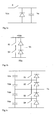
- FIG.1(a) shows a dc-dc chopper circuit that is commonly used for driving dc motors.
- the switch (S) When the switch (S) is turned on, the output voltage ( Vs ) for driving the motor is Vdc.
- the switch is turned off, the motor current will flow through the diode so that the converter output voltage is zero.
- FIG.1(b) shows one power inverter leg. S1 and S2 are switched in a complimentary manner. That is, when S1 is turned on, S2 is turned off , and vice versa.
- the output voltage of this inverter leg can be expressed as:
- FIG.1(c) A 3-level inverter is shown in FIG.1(c) .
- the output voltage can be:
- FIG.2 shows the typical changes of q with time for a 2-level power inverter over one cycle.
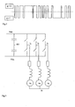
- Fig.3 shows a schematic of a 2-level power inverter driving a 3-phase motor.
- the equivalent circuit of a power inverter driven (ac or dc) motor can be simplified to a per-phase model as shown in Fig.4 .
- Vs input voltage
- Vs is modeled as an ac voltage source with discrete voltage levels generated by the power inverter circuit.
- Vs is switched at Vdc or OV.
- R is the winding resistance
- L is the inductance of the motor winding
- k is a motor constant
- ⁇ is the motor speed.
- the back electromotive force (emf) is proportional to the speed of the motor.
- the back emf is represented as an ac voltage source for an ac motor and a dc voltage source for a dc motor.
- V s Ri S + L ⁇ di S dt + k ⁇
- Vs q . Vdc
- q is an integer that changes in real-time according to the switching strategy.
- PWM pulse-width-modulation
- the instantaneous value of q is determined by the switching control of the power inverter which is therefore known in the controller.
- preferred embodiments of the present invention use the instantaneous PWM voltage waveform for Vs.
- This exact PWM voltage waveform includes the full harmonic content of the applied voltage to the motor. Consequently, the proposed method can work well at low speeds because the instantaneous information that is particularly important at low speed is not filtered away.
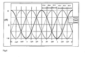
- FIG.5 shows part of an ideal sinusoidal current waveform and a typical switched current waveform.
- the actual stator current is switched at high frequency and the current waveform ramps up and down to follow the ideal sinusoidal waveform.
- the solid switching current represents an actual stator current in a motor while the smooth dotted current waveform represents the filtered current.
- the current ripple is filtered so that a good sinusoidal current signal is obtained.
- the slope of the current (di s /d t ) used in many existing motor control methods is the slope of the filtered current.
- filtering techniques have the effect of eliminating a lot of useful instantaneous information that is needed in the speed estimation.
- the sampled di s /d t is the instantaneous slope of the actual switching current during each inverter switching state.
- the slope of the filtered or ideal sinusoidal waveform is "always positive”. But if we determine the slope of the actual current waveform at each inverter switching state, the slope can be "positive or negative”.
- equation (6) shows that the instantaneous motor speed ⁇ can be determined from
- Equation (7) shows the basic concept of the speed estimation of the motor in a discrete form.
- various forms of digital filtering techniques can be employed to modify equation (7) in order to reduce the sampling noise for the digital controller.
- any noise filtering by the digital filter does not remove the current ripples, above and below the ideal waveform, caused by the inverter switching.
- V ⁇ ABCS R ⁇ S ⁇ i ⁇ ABCS + d ⁇ ⁇ ⁇ ABCS dt
- V ⁇ ABCS V A V B V C
- R ⁇ S R 0 0 0 R 0 0 R
- ⁇ ⁇ L ⁇ S ⁇ i ⁇ ABCS + ⁇ ⁇ m
- L ⁇ S L S L M L M L M L S L M L M L S
- ⁇ is the total flux linkage
- ⁇ m is the flux linkages established by the permanent magnet as viewed by the stator windings
- ⁇ e electrical angle
- ⁇ r mechanical angle
- ⁇ o initial angle
- P number of poles
- L S self-inductance of stator winding
- L M mutual inductance between two stator windings
- ⁇ e electrical rotor angular speed
- ⁇ m mechanical rotor angular speed
- v X refers to the instantaneous inverter voltage level of phase- X
- i X refers to the instantaneous motor current of phase- X
- R is the resistance of the phase winding
- Ls is the self-inductance of the stator windings
- L M is the mutual in
- Equations (11) and (12) indicates that, for a star-connected 3-phase load, two current sensors are sufficient to get all instantaneous information of the 3 phase currents and the three rates of change of current. For example, measuring i A and i B allows one to determine i C . Similarly, di C / dt can be determined from the negative value of the sum of di A / dt and di B / dt.
- v A Ri A + L S ⁇ di A dt + L M ⁇ di B dt + di C dt + k P 2 ⁇ ⁇ A ⁇ cos ⁇ e ⁇ t - ⁇
- ⁇ B 1 k P / 2 ⁇ cos ⁇ e ⁇ t - ⁇ o - 2 ⁇ ⁇ / 3 q B ⁇ Vdc - Ri B
- * ⁇ C 1 k P / 2 ⁇ cos ⁇ e ⁇ t - ⁇ o + 2 ⁇ ⁇ / 3 q C ⁇ Vdc - Ri C
- the method for instantaneous speed estimation based on the instantaneous sampled di/dt of the stator currents is illustrated in a motor with sinusoidal back emf. In principle, it can be extended to other types of motors as long as the waveforms of the back emf are known.
- the invention here can eliminate not only the speed sensor but also the position sensor because the initial angle ⁇ o can also be eliminated.
- Equation (20) can be used to determine the speed of the motor.
- the direction of the motor can be checked from the sequence of sampled values of ⁇ A * , ⁇ B * and ⁇ C * because they represent a 3-phase system with 120 degrees apart.
- the direction of the rotation can be determined from the sequence of y A , y B and y C (i.e. stepped-down versions of the three back emfs) from equations (15a), (15b) and (15c) respectively.
- y A , y B and y C are very small values
- the motor constant k in equations (15a), (15b) and (15c) can be artificially reduced to a lower value so as to amplify y A , y B and y C at the low speed region. In this way, the resolution of y A , y B and y C can be improved even at low speeds.
- motor parameters such as winding resistance R, self-inductance Ls and mutual inductance Lm , and motor constant k could be nonlinear.
- winding resistance is a function of the temperature and so R can be expressed as R(T) where T is temperature and Ls(i s ) where i s is the stator current etc.
- Figure 7 shows an example configuration of a motor and apparatus for controlling the motor and for providing information about the operation of a motor.
- the AC motor is powered by a DC power supply 120 and a PWM power inverter 130.
- the power inverter has a plurality of switches 135.
- the power inverter converts the DC current from the power supply into AC current for supplying the motor.
- the power inverter shown in Fig. 7 is a 3-phase power inverter with two stages. Three different phases are tapped off the inverter by lines 140, 141 and 143 which couple to the motor.
- inverter could be used, e.g. with more or fewer stages.
- current having three phases is preferred, the invention could also be applied to power supplies having a different number of phases.
- a plurality of samplers 150, 151 sample the instantaneous current value on at least two of the three phase lines 140, 141, 143 leading to the motor.
- the current is measured using any known means, for example a hall effect sensor.
- the instantaneous current information is provided to a processor 160.
- the processor calculates the instantaneous current of the third phase based on the instantaneous current of the other phases. If the motor windings are star-connected, the processor calculates the instantaneous current of the third phase based on the presumption that the sum of the instantaneous currents of each phase should be approximately zero.
- the processor 160 determines the rate of change of instantaneous current for each phase (first phase, second phase, third phase).
- Both the instantaneous current values and the rates of change for each phase are calculated based on raw unfiltered measurements of the current.
- the instantaneous current values may be filtered in such a way that the information from current ripples due to inverter switching is maintained. That is the filter only removes noise spikes or background noise and does not remove or smooth out current values which are above or below the 'ideal' current waveform, due to switching effects. In this way important information is retained and used by the processer in its calculation of the rate of change of instantaneous current, back emfs, motor speed, position, direction of rotation etc.
- a digital filter may be used for this purpose. However, it is not simply a low pass filter which removes all harmonics above a certain frequency, including ripples due to switching. On the contrary, current ripples due to switching are retained and passed through the filter.
- the processor 160 uses the rate of change for each phase to calculate or predict the speed of rotation, position and/or direction of rotation of the rotor.
- a controller 170 is coupled to the motor, DC power supply and the power inverter. The controller 170 controls the motor and the supply of electricity to the motor based on the speed of rotation, position and/or direction of rotation of the rotor calculated by the processor. While the samplers 150, 151, processor 160 and controller 170 have been shown as separate elements in Fig. 7 , two or all of them may optionally be combined as a single module. For example, a single processing device may be able to perform the functions of the processor and controller. The sampler, processor and controller may use digital or analog technology.
- step 200 the samplers 150, 151 sample the instantaneous motor current for two phases. Preferably a plurality of samples is taken for each phase, the sample frequency being higher than the switching frequency of the power inverter 130.
- step 205 the processor calculates the instantaneous current of the third phase based on the measurements of current for the first two phases.
- step 210 the rate of change of the instantaneous current in each phase is determined from the current samples taken in step 200.
- step 220 the information from the different phases is optionally checked for errors. For example, if the instantaneous current or rate of change for one phase is significantly different than expected (e.g. due to a noise spike) the data set for that time period may be discarded.
- step 230 stepped down back emf functions are calculated for each phase.
- step 240 the speed of the motor is calculated based on the stepped down back emf functions.
- step 250 the position of the rotor may be estimated and/or the direction of rotation of the motor may be determined.
- step 260 the motor is controlled based on the information provided in steps 240 and/or 250. For example, the motor may be controlled to run at a predetermined speed. If, in step 240, it is determined that the motor is currently operating at a slower speed than the predetermined speed, then its speed may be increased (e.g. by increasing the driving current through PWM or otherwise). If, in step 240, it is determined that the motor is running too quickly, then it may be slowed down in step 260.
Landscapes
- Engineering & Computer Science (AREA)
- Power Engineering (AREA)
- Control Of Motors That Do Not Use Commutators (AREA)
- Control Of Electric Motors In General (AREA)
Applications Claiming Priority (1)
| Application Number | Priority Date | Filing Date | Title |
|---|---|---|---|
| US12/501,645 US8339078B2 (en) | 2009-07-13 | 2009-07-13 | Apparatus and method for providing information relating to a motor |
Publications (3)
| Publication Number | Publication Date |
|---|---|
| EP2276167A2 true EP2276167A2 (fr) | 2011-01-19 |
| EP2276167A3 EP2276167A3 (fr) | 2012-04-25 |
| EP2276167B1 EP2276167B1 (fr) | 2017-03-15 |
Family
ID=43018244
Family Applications (1)
| Application Number | Title | Priority Date | Filing Date |
|---|---|---|---|
| EP10251216.7A Not-in-force EP2276167B1 (fr) | 2009-07-13 | 2010-07-07 | Appareil et procédé de fourniture d'informations liées à un moteur |
Country Status (2)
| Country | Link |
|---|---|
| US (1) | US8339078B2 (fr) |
| EP (1) | EP2276167B1 (fr) |
Cited By (1)
| Publication number | Priority date | Publication date | Assignee | Title |
|---|---|---|---|---|
| GB2581187A (en) * | 2019-02-07 | 2020-08-12 | Stannah Stairlifts Ltd | Electric motor control |
Families Citing this family (8)
| Publication number | Priority date | Publication date | Assignee | Title |
|---|---|---|---|---|
| US9780718B2 (en) * | 2010-11-02 | 2017-10-03 | Whirlpool Corporation | Portable appliance motor control with speed-based current limitation |
| US8796983B2 (en) | 2011-02-24 | 2014-08-05 | Deere & Company | Method and system for determining a position of a rotor of an electric motor with noise reduction |
| US8471589B2 (en) * | 2011-06-16 | 2013-06-25 | GM Global Technology Operations LLC | Method and apparatus for alternator stator turn-to-turn short detection |
| US9954624B2 (en) * | 2012-04-27 | 2018-04-24 | The Board Of Trustees Of The University Of Illinois | Angle-based speed estimation of alternating current machines utilizing a median filter |
| CN103259487B (zh) * | 2013-04-16 | 2015-09-09 | 深圳市海浦蒙特科技有限公司 | 变频器控制电机的方法和变频器 |
| CN107450041B (zh) * | 2017-06-30 | 2020-02-07 | 珠海格力电器股份有限公司 | 用于同步电机的电流传感器故障诊断方法、装置及变频器 |
| CN109188046B (zh) * | 2018-07-05 | 2020-11-10 | 广东高标电子科技有限公司 | 单电阻电机电流采样方法、电机驱动电路及可读存储介质 |
| US11711034B2 (en) * | 2020-12-01 | 2023-07-25 | Kohler Co. | Sensorless position detection for electric machine |
Family Cites Families (12)
| Publication number | Priority date | Publication date | Assignee | Title |
|---|---|---|---|---|
| US4527101A (en) * | 1983-11-23 | 1985-07-02 | Black & Decker Inc. | Universal electric motor speed sensing by using Fourier transform method |
| DE69314612T2 (de) * | 1992-12-17 | 1998-02-12 | Lg Electronics Inc., Seoul/Soul | Sensorloser, geschalteter Reluktanzmotor |
| US5448149A (en) * | 1994-06-20 | 1995-09-05 | Texas A&M University | Indirect rotor position sensor for a sinusoidal synchronous reluctance machine |
| US5821713A (en) * | 1995-09-11 | 1998-10-13 | Advanced Motion Controls, Inc. | Commutation position detection system and method |
| US6172498B1 (en) * | 1998-09-29 | 2001-01-09 | Rockwell Technologies, Llc | Method and apparatus for rotor angle detection |
| US6879129B2 (en) * | 2001-03-29 | 2005-04-12 | Matsushita Electric Industrial Co., Ltd. | Brushless motor control method and controller |
| JP4367279B2 (ja) * | 2004-07-14 | 2009-11-18 | 株式会社デンソー | 同期モータの制御装置 |
| US7468595B2 (en) * | 2005-07-26 | 2008-12-23 | Eaton Corporation | System and method of controlling the start-up of an adjustable speed motor drive based sinusoidal output power conditioner |
| FI118583B (fi) * | 2006-06-01 | 2007-12-31 | Vacon Oyj | Taajuusmuuttajan virran mittaus |
| JP2007336641A (ja) * | 2006-06-13 | 2007-12-27 | Denso Corp | 同期モータの位置センサレス駆動装置 |
| WO2009090755A1 (fr) * | 2008-01-18 | 2009-07-23 | Mitsubishi Electric Corporation | Unité de commande de convertisseur de puissance |
| GB0808342D0 (en) * | 2008-05-08 | 2008-06-18 | Trw Ltd | Position sensorless motor control |
-
2009
- 2009-07-13 US US12/501,645 patent/US8339078B2/en not_active Expired - Fee Related
-
2010
- 2010-07-07 EP EP10251216.7A patent/EP2276167B1/fr not_active Not-in-force
Non-Patent Citations (2)
| Title |
|---|
| "Adaptive controller design for a sensorless IPMSM drive system with a maximum torque control", IEE PROCEEDINGS ON ELECTRIC POWER APPLICATIONS, vol. 153, no. 6, November 2006 (2006-11-01), pages 823 - 833 |
| J.L. SHI; T.H. LIU; Y.C. CHANG: "Position control of an interior permanent-magnetic synchronous motor without using a shaft position sensor", IEEE TRANSACTIONS ON INDUSTRIAL ELECTRONICS, vol. 54, no. 4, August 2007 (2007-08-01), pages 1989 - 2000 |
Cited By (2)
| Publication number | Priority date | Publication date | Assignee | Title |
|---|---|---|---|---|
| GB2581187A (en) * | 2019-02-07 | 2020-08-12 | Stannah Stairlifts Ltd | Electric motor control |
| WO2020161496A1 (fr) * | 2019-02-07 | 2020-08-13 | Stannah Stairlifts Limited | Commande de moteur électrique |
Also Published As
| Publication number | Publication date |
|---|---|
| US20110006714A1 (en) | 2011-01-13 |
| US8339078B2 (en) | 2012-12-25 |
| EP2276167B1 (fr) | 2017-03-15 |
| EP2276167A3 (fr) | 2012-04-25 |
Similar Documents
| Publication | Publication Date | Title |
|---|---|---|
| EP2276167B1 (fr) | Appareil et procédé de fourniture d'informations liées à un moteur | |
| EP2757670B1 (fr) | Procédé et appareil de commande de convertisseur de puissance à filtre de sortie de l'onduleur | |
| Johnson et al. | Review of sensorless methods for brushless DC | |
| US8810169B2 (en) | Method and system for estimating rotor angle of an electric machine | |
| US9294019B2 (en) | Method and apparatus for controlling power converter with inverter output filter | |
| US20070296371A1 (en) | Position sensorless control apparatus for synchronous motor | |
| EP4007158B1 (fr) | Procédé de commande et dispositif de commande | |
| JP2004282969A (ja) | 交流電動機の制御装置及び制御方法 | |
| US8872457B2 (en) | Method and apparatus for driving a polyphase electronically commutated electric machine and a motor system | |
| JP6953763B2 (ja) | モータ制御装置 | |
| CN114270695B (zh) | 推测装置以及交流电动机的驱动装置 | |
| Park et al. | Sensorless control of brushless DC motors with torque constant estimation for home appliances | |
| CN103647482B (zh) | 无刷直流电机180°方波控制方法及其控制模块和变频器 | |
| JP4663684B2 (ja) | 交流電動機の制御装置及び制御方法 | |
| Darba et al. | Sensorless commutation and speed control of Brushless DC-machine drives based on the back-EMF symmetric threshold-tracking | |
| JP6914787B2 (ja) | モータ制御用集積回路 | |
| CN120320641A (zh) | 电动机的励磁位置检测方法 | |
| JP5396754B2 (ja) | 出力推定装置 | |
| JP5186352B2 (ja) | 電動機の磁極位置推定装置 | |
| KR100637383B1 (ko) | 자속 관측기를 이용한 유도 전동기의 속도 추정 장치 및이를 이용한 제어시스템 | |
| JP3797484B2 (ja) | ステッピングモータの駆動装置 | |
| JP3696786B2 (ja) | モータ制御装置 | |
| Komatsuzaki et al. | A position sensorless drive using estimation of turn-off angle under regenerative braking in switched reluctance motor | |
| KR102730006B1 (ko) | 단일 전류 센서를 활용한 교류 전동기 센서리스 구동 시스템 | |
| KR101694167B1 (ko) | 동기 전동기의 위치 추정 방법 및 이를 이용한 전동기 구동장치 |
Legal Events
| Date | Code | Title | Description |
|---|---|---|---|
| PUAI | Public reference made under article 153(3) epc to a published international application that has entered the european phase |
Free format text: ORIGINAL CODE: 0009012 |
|
| AK | Designated contracting states |
Kind code of ref document: A2 Designated state(s): AL AT BE BG CH CY CZ DE DK EE ES FI FR GB GR HR HU IE IS IT LI LT LU LV MC MK MT NL NO PL PT RO SE SI SK SM TR |
|
| AX | Request for extension of the european patent |
Extension state: BA ME RS |
|
| PUAL | Search report despatched |
Free format text: ORIGINAL CODE: 0009013 |
|
| AK | Designated contracting states |
Kind code of ref document: A3 Designated state(s): AL AT BE BG CH CY CZ DE DK EE ES FI FR GB GR HR HU IE IS IT LI LT LU LV MC MK MT NL NO PL PT RO SE SI SK SM TR |
|
| AX | Request for extension of the european patent |
Extension state: BA ME RS |
|
| RIC1 | Information provided on ipc code assigned before grant |
Ipc: H02P 27/08 20060101ALI20120320BHEP Ipc: H02P 6/18 20060101AFI20120320BHEP |
|
| 17P | Request for examination filed |
Effective date: 20121016 |
|
| 17Q | First examination report despatched |
Effective date: 20140708 |
|
| REG | Reference to a national code |
Ref country code: DE Ref legal event code: R079 Ref document number: 602010040729 Country of ref document: DE Free format text: PREVIOUS MAIN CLASS: H02P0006180000 Ipc: H02P0006000000 |
|
| GRAP | Despatch of communication of intention to grant a patent |
Free format text: ORIGINAL CODE: EPIDOSNIGR1 |
|
| RIC1 | Information provided on ipc code assigned before grant |
Ipc: H02P 6/18 20160101ALI20160915BHEP Ipc: H02P 27/08 20060101ALI20160915BHEP Ipc: H02P 6/00 20160101AFI20160915BHEP |
|
| INTG | Intention to grant announced |
Effective date: 20161004 |
|
| GRAS | Grant fee paid |
Free format text: ORIGINAL CODE: EPIDOSNIGR3 |
|
| GRAA | (expected) grant |
Free format text: ORIGINAL CODE: 0009210 |
|
| AK | Designated contracting states |
Kind code of ref document: B1 Designated state(s): AL AT BE BG CH CY CZ DE DK EE ES FI FR GB GR HR HU IE IS IT LI LT LU LV MC MK MT NL NO PL PT RO SE SI SK SM TR |
|
| REG | Reference to a national code |
Ref country code: CH Ref legal event code: EP Ref country code: GB Ref legal event code: FG4D |
|
| REG | Reference to a national code |
Ref country code: IE Ref legal event code: FG4D |
|
| REG | Reference to a national code |
Ref country code: AT Ref legal event code: REF Ref document number: 876486 Country of ref document: AT Kind code of ref document: T Effective date: 20170415 |
|
| REG | Reference to a national code |
Ref country code: DE Ref legal event code: R096 Ref document number: 602010040729 Country of ref document: DE |
|
| REG | Reference to a national code |
Ref country code: NL Ref legal event code: MP Effective date: 20170315 |
|
| REG | Reference to a national code |
Ref country code: LT Ref legal event code: MG4D |
|
| PG25 | Lapsed in a contracting state [announced via postgrant information from national office to epo] |
Ref country code: HR Free format text: LAPSE BECAUSE OF FAILURE TO SUBMIT A TRANSLATION OF THE DESCRIPTION OR TO PAY THE FEE WITHIN THE PRESCRIBED TIME-LIMIT Effective date: 20170315 Ref country code: GR Free format text: LAPSE BECAUSE OF FAILURE TO SUBMIT A TRANSLATION OF THE DESCRIPTION OR TO PAY THE FEE WITHIN THE PRESCRIBED TIME-LIMIT Effective date: 20170616 Ref country code: NO Free format text: LAPSE BECAUSE OF FAILURE TO SUBMIT A TRANSLATION OF THE DESCRIPTION OR TO PAY THE FEE WITHIN THE PRESCRIBED TIME-LIMIT Effective date: 20170615 Ref country code: LT Free format text: LAPSE BECAUSE OF FAILURE TO SUBMIT A TRANSLATION OF THE DESCRIPTION OR TO PAY THE FEE WITHIN THE PRESCRIBED TIME-LIMIT Effective date: 20170315 Ref country code: FI Free format text: LAPSE BECAUSE OF FAILURE TO SUBMIT A TRANSLATION OF THE DESCRIPTION OR TO PAY THE FEE WITHIN THE PRESCRIBED TIME-LIMIT Effective date: 20170315 |
|
| REG | Reference to a national code |
Ref country code: AT Ref legal event code: MK05 Ref document number: 876486 Country of ref document: AT Kind code of ref document: T Effective date: 20170315 |
|
| PG25 | Lapsed in a contracting state [announced via postgrant information from national office to epo] |
Ref country code: LV Free format text: LAPSE BECAUSE OF FAILURE TO SUBMIT A TRANSLATION OF THE DESCRIPTION OR TO PAY THE FEE WITHIN THE PRESCRIBED TIME-LIMIT Effective date: 20170315 Ref country code: SE Free format text: LAPSE BECAUSE OF FAILURE TO SUBMIT A TRANSLATION OF THE DESCRIPTION OR TO PAY THE FEE WITHIN THE PRESCRIBED TIME-LIMIT Effective date: 20170315 Ref country code: BG Free format text: LAPSE BECAUSE OF FAILURE TO SUBMIT A TRANSLATION OF THE DESCRIPTION OR TO PAY THE FEE WITHIN THE PRESCRIBED TIME-LIMIT Effective date: 20170615 |
|
| PG25 | Lapsed in a contracting state [announced via postgrant information from national office to epo] |
Ref country code: NL Free format text: LAPSE BECAUSE OF FAILURE TO SUBMIT A TRANSLATION OF THE DESCRIPTION OR TO PAY THE FEE WITHIN THE PRESCRIBED TIME-LIMIT Effective date: 20170315 |
|
| PG25 | Lapsed in a contracting state [announced via postgrant information from national office to epo] |
Ref country code: AT Free format text: LAPSE BECAUSE OF FAILURE TO SUBMIT A TRANSLATION OF THE DESCRIPTION OR TO PAY THE FEE WITHIN THE PRESCRIBED TIME-LIMIT Effective date: 20170315 Ref country code: EE Free format text: LAPSE BECAUSE OF FAILURE TO SUBMIT A TRANSLATION OF THE DESCRIPTION OR TO PAY THE FEE WITHIN THE PRESCRIBED TIME-LIMIT Effective date: 20170315 Ref country code: CZ Free format text: LAPSE BECAUSE OF FAILURE TO SUBMIT A TRANSLATION OF THE DESCRIPTION OR TO PAY THE FEE WITHIN THE PRESCRIBED TIME-LIMIT Effective date: 20170315 Ref country code: RO Free format text: LAPSE BECAUSE OF FAILURE TO SUBMIT A TRANSLATION OF THE DESCRIPTION OR TO PAY THE FEE WITHIN THE PRESCRIBED TIME-LIMIT Effective date: 20170315 Ref country code: IT Free format text: LAPSE BECAUSE OF FAILURE TO SUBMIT A TRANSLATION OF THE DESCRIPTION OR TO PAY THE FEE WITHIN THE PRESCRIBED TIME-LIMIT Effective date: 20170315 Ref country code: ES Free format text: LAPSE BECAUSE OF FAILURE TO SUBMIT A TRANSLATION OF THE DESCRIPTION OR TO PAY THE FEE WITHIN THE PRESCRIBED TIME-LIMIT Effective date: 20170315 Ref country code: SK Free format text: LAPSE BECAUSE OF FAILURE TO SUBMIT A TRANSLATION OF THE DESCRIPTION OR TO PAY THE FEE WITHIN THE PRESCRIBED TIME-LIMIT Effective date: 20170315 |
|
| PG25 | Lapsed in a contracting state [announced via postgrant information from national office to epo] |
Ref country code: SM Free format text: LAPSE BECAUSE OF FAILURE TO SUBMIT A TRANSLATION OF THE DESCRIPTION OR TO PAY THE FEE WITHIN THE PRESCRIBED TIME-LIMIT Effective date: 20170315 Ref country code: IS Free format text: LAPSE BECAUSE OF FAILURE TO SUBMIT A TRANSLATION OF THE DESCRIPTION OR TO PAY THE FEE WITHIN THE PRESCRIBED TIME-LIMIT Effective date: 20170715 Ref country code: PL Free format text: LAPSE BECAUSE OF FAILURE TO SUBMIT A TRANSLATION OF THE DESCRIPTION OR TO PAY THE FEE WITHIN THE PRESCRIBED TIME-LIMIT Effective date: 20170315 Ref country code: PT Free format text: LAPSE BECAUSE OF FAILURE TO SUBMIT A TRANSLATION OF THE DESCRIPTION OR TO PAY THE FEE WITHIN THE PRESCRIBED TIME-LIMIT Effective date: 20170717 |
|
| REG | Reference to a national code |
Ref country code: DE Ref legal event code: R097 Ref document number: 602010040729 Country of ref document: DE |
|
| PLBE | No opposition filed within time limit |
Free format text: ORIGINAL CODE: 0009261 |
|
| STAA | Information on the status of an ep patent application or granted ep patent |
Free format text: STATUS: NO OPPOSITION FILED WITHIN TIME LIMIT |
|
| PG25 | Lapsed in a contracting state [announced via postgrant information from national office to epo] |
Ref country code: DK Free format text: LAPSE BECAUSE OF FAILURE TO SUBMIT A TRANSLATION OF THE DESCRIPTION OR TO PAY THE FEE WITHIN THE PRESCRIBED TIME-LIMIT Effective date: 20170315 |
|
| REG | Reference to a national code |
Ref country code: DE Ref legal event code: R119 Ref document number: 602010040729 Country of ref document: DE |
|
| 26N | No opposition filed |
Effective date: 20171218 |
|
| PG25 | Lapsed in a contracting state [announced via postgrant information from national office to epo] |
Ref country code: SI Free format text: LAPSE BECAUSE OF FAILURE TO SUBMIT A TRANSLATION OF THE DESCRIPTION OR TO PAY THE FEE WITHIN THE PRESCRIBED TIME-LIMIT Effective date: 20170315 |
|
| REG | Reference to a national code |
Ref country code: CH Ref legal event code: PL |
|
| REG | Reference to a national code |
Ref country code: IE Ref legal event code: MM4A |
|
| REG | Reference to a national code |
Ref country code: FR Ref legal event code: ST Effective date: 20180330 |
|
| PG25 | Lapsed in a contracting state [announced via postgrant information from national office to epo] |
Ref country code: IE Free format text: LAPSE BECAUSE OF NON-PAYMENT OF DUE FEES Effective date: 20170707 Ref country code: CH Free format text: LAPSE BECAUSE OF NON-PAYMENT OF DUE FEES Effective date: 20170731 Ref country code: DE Free format text: LAPSE BECAUSE OF NON-PAYMENT OF DUE FEES Effective date: 20180201 Ref country code: LI Free format text: LAPSE BECAUSE OF NON-PAYMENT OF DUE FEES Effective date: 20170731 |
|
| PG25 | Lapsed in a contracting state [announced via postgrant information from national office to epo] |
Ref country code: FR Free format text: LAPSE BECAUSE OF NON-PAYMENT OF DUE FEES Effective date: 20170731 |
|
| REG | Reference to a national code |
Ref country code: BE Ref legal event code: MM Effective date: 20170731 |
|
| PG25 | Lapsed in a contracting state [announced via postgrant information from national office to epo] |
Ref country code: LU Free format text: LAPSE BECAUSE OF NON-PAYMENT OF DUE FEES Effective date: 20170707 |
|
| PG25 | Lapsed in a contracting state [announced via postgrant information from national office to epo] |
Ref country code: BE Free format text: LAPSE BECAUSE OF NON-PAYMENT OF DUE FEES Effective date: 20170731 |
|
| PG25 | Lapsed in a contracting state [announced via postgrant information from national office to epo] |
Ref country code: MT Free format text: LAPSE BECAUSE OF NON-PAYMENT OF DUE FEES Effective date: 20170707 |
|
| PG25 | Lapsed in a contracting state [announced via postgrant information from national office to epo] |
Ref country code: MC Free format text: LAPSE BECAUSE OF FAILURE TO SUBMIT A TRANSLATION OF THE DESCRIPTION OR TO PAY THE FEE WITHIN THE PRESCRIBED TIME-LIMIT Effective date: 20170315 Ref country code: HU Free format text: LAPSE BECAUSE OF FAILURE TO SUBMIT A TRANSLATION OF THE DESCRIPTION OR TO PAY THE FEE WITHIN THE PRESCRIBED TIME-LIMIT; INVALID AB INITIO Effective date: 20100707 |
|
| PG25 | Lapsed in a contracting state [announced via postgrant information from national office to epo] |
Ref country code: CY Free format text: LAPSE BECAUSE OF NON-PAYMENT OF DUE FEES Effective date: 20170315 |
|
| PG25 | Lapsed in a contracting state [announced via postgrant information from national office to epo] |
Ref country code: MK Free format text: LAPSE BECAUSE OF FAILURE TO SUBMIT A TRANSLATION OF THE DESCRIPTION OR TO PAY THE FEE WITHIN THE PRESCRIBED TIME-LIMIT Effective date: 20170315 |
|
| PG25 | Lapsed in a contracting state [announced via postgrant information from national office to epo] |
Ref country code: TR Free format text: LAPSE BECAUSE OF FAILURE TO SUBMIT A TRANSLATION OF THE DESCRIPTION OR TO PAY THE FEE WITHIN THE PRESCRIBED TIME-LIMIT Effective date: 20170315 |
|
| PG25 | Lapsed in a contracting state [announced via postgrant information from national office to epo] |
Ref country code: AL Free format text: LAPSE BECAUSE OF FAILURE TO SUBMIT A TRANSLATION OF THE DESCRIPTION OR TO PAY THE FEE WITHIN THE PRESCRIBED TIME-LIMIT Effective date: 20170315 |
|
| PGFP | Annual fee paid to national office [announced via postgrant information from national office to epo] |
Ref country code: GB Payment date: 20200624 Year of fee payment: 11 |
|
| GBPC | Gb: european patent ceased through non-payment of renewal fee |
Effective date: 20210707 |
|
| PG25 | Lapsed in a contracting state [announced via postgrant information from national office to epo] |
Ref country code: GB Free format text: LAPSE BECAUSE OF NON-PAYMENT OF DUE FEES Effective date: 20210707 |