EP2276583B1 - Antenne acoustique a circuits imprimes integres - Google Patents
Antenne acoustique a circuits imprimes integres Download PDFInfo
- Publication number
- EP2276583B1 EP2276583B1 EP09750050.8A EP09750050A EP2276583B1 EP 2276583 B1 EP2276583 B1 EP 2276583B1 EP 09750050 A EP09750050 A EP 09750050A EP 2276583 B1 EP2276583 B1 EP 2276583B1
- Authority
- EP
- European Patent Office
- Prior art keywords
- transducers
- printed circuit
- acoustic
- antenna
- elementary
- Prior art date
- Legal status (The legal status is an assumption and is not a legal conclusion. Google has not performed a legal analysis and makes no representation as to the accuracy of the status listed.)
- Active
Links
Images

Classifications
-
- B—PERFORMING OPERATIONS; TRANSPORTING
- B06—GENERATING OR TRANSMITTING MECHANICAL VIBRATIONS IN GENERAL
- B06B—METHODS OR APPARATUS FOR GENERATING OR TRANSMITTING MECHANICAL VIBRATIONS OF INFRASONIC, SONIC, OR ULTRASONIC FREQUENCY, e.g. FOR PERFORMING MECHANICAL WORK IN GENERAL
- B06B1/00—Methods or apparatus for generating mechanical vibrations of infrasonic, sonic, or ultrasonic frequency
- B06B1/02—Methods or apparatus for generating mechanical vibrations of infrasonic, sonic, or ultrasonic frequency making use of electrical energy
- B06B1/06—Methods or apparatus for generating mechanical vibrations of infrasonic, sonic, or ultrasonic frequency making use of electrical energy operating with piezoelectric effect or with electrostriction
- B06B1/0607—Methods or apparatus for generating mechanical vibrations of infrasonic, sonic, or ultrasonic frequency making use of electrical energy operating with piezoelectric effect or with electrostriction using multiple elements
- B06B1/0622—Methods or apparatus for generating mechanical vibrations of infrasonic, sonic, or ultrasonic frequency making use of electrical energy operating with piezoelectric effect or with electrostriction using multiple elements on one surface
- B06B1/0629—Square array
Definitions
- the present invention relates to an integrated printed circuit acoustic antenna, and in particular to a low cost acoustic antenna.
- the acoustic transduction technology conventionally used in underwater applications and having the best compromise between radiated sound power and usable bandwidth is "Tonpilz”.
- This system is an electro-acoustic converter of mass-spring-mass type with symmetry of revolution functioning generally in dilation / compression.
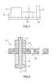
- FIG 1 such a Tonpilz type transducer. It essentially comprises a stack 1 of piezoelectric ceramic discs (or electrostrictive) clamped between a thick disc 2 forming a counterweight and a disc 3 less thick than the disk 2 and flag. All these discs are pierced with a central opening allowing the passage of a clamping rod 4 which ensures their tightening with a nut 5.
- each of the elements represented in figure 1 ensures a very particular role: the driving function is provided by the pillar 1 of piezoelectric ceramics electrically interconnected by electrodes 1A formed on their flat faces vis-à-vis. The ceramics are wired in parallel.
- the flag 3 ensures the acoustic coupling with the medium and also makes it possible to widen the band by clean mode known as "papillonnage". It is he who determines the geometry of the radiated field (directivity diagram).
- Countermass 2 stabilizes the system and channels the radiated energy in a single direction of space.
- the prestressing rod 4 and the clamping nut 5 guarantee the operation of the device (transducer) in expansion / compression.
- the amount of wiring by welding to achieve is very quickly rhédibitoire for high frequency antennas (greater than 50kHz), composed of a large number of small transducers, for example, and not limited to, 128 elementary transducers 150kHz .
- This cabling, welding and tracking station which is very difficult to automate, is very often in practice the heavier workstation in the process of mounting an acoustic antenna.
- An acoustic antenna comprising a network of elementary transducers mounted on a printed circuit is presented in the document US 6,181,052 B1 .
- the present invention relates to a low cost acoustic antenna requiring the minimum possible assembly operations, these operations can be easily automated.
- the term "acoustic" is used here, but it is understood that the operating frequency band of the antenna of the invention may be greater than and even substantially greater than the sound frequencies; it may range for example from 20 kHz to several hundred kHz, and typically, but not exclusively, it may be the 140-160 kHz frequency band.
- the acoustic antenna according to the invention is characterized in that it comprises a network of elementary transducers, each elementary transducer comprising, between a counter-mass and a horn, at least one ceramic, all the elementary transducers being mounted on a common printed circuit for electrical connection between the transducers and for positioning the transducers relative to one another, and at least one connector fixed on this printed circuit, each of the transducers being mounted so that the printed circuit is clamped between his (its) ceramics (s) and its counter-mass.
- the elementary transducers are of one of the following electro-acoustic types: piezoelectric or electrostrictive.
- An object of the present invention consists in eliminating, during the manufacturing process, the positioning stations of the transducers on their support and the welding of their connection electrodes (transducer supply wires) of the manufacturing process of the tonpilz type antennas to high frequency with a large number of elements.
- the invention provides, according to a preferred embodiment, to reduce the ceramic pillar of Tonpilz to a single ceramic and fix the various pillars on a printed circuit common to the entire antenna in the tonpilz structure, between the ceramic and the countermeasures, to ensure the electrical connection of all elements of the antenna and to fix stably the arrangement of the transducers relative to each other. It is understood that the invention is not limited to single ceramic transducers, and that these transducers may include more.
- the insulating material of the printed circuit is chosen according to the characteristics of the transducers used, for example, and without limitation, this material may be epoxy glass or any screen-printing medium.
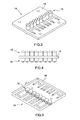
- the transducer 6 essentially comprises a tubular ceramic 8, a horn 9 These three elements 8 to 10 are assembled in the following manner on the printed circuit 7 by means of a screw 11 passing through a hole in this printed circuit: the counter-mass 10 is applied on one side of the printed circuit, while the ceramic 8 is applied on the other side of this circuit, and the horn 9 is applied on the free planar face of the ceramic 8.
- the screw 11 thus freely traverses the elements 10, 7, and 8 and is screwed into a threaded axial bore of the horn 9.
- the common axis of all these elements is referenced 12.
- a large number (a hundred or more) other transducers can be fixed on the printed circuit 7, and by way of example, there is shown a bore 13 formed in this printed circuit for fixing a transducer neighbor transducer 6.
- the topology of implantation of different transducers on the printed circuit 7 e st determined in a manner known per se to obtain a desired radiation pattern and, if necessary, to be able to implement a beam formation and orientation system.
- the electrical connections are ensured in the following way.
- the printed circuit 7 recovers each of the positive and negative points of the transducer on its two main faces.
- the positive connection is obtained by the direct contact of a plane face of the ceramic on the printed circuit 7.
- the negative connection is obtained indirectly: the other flat face of the ceramic is in direct contact with the horn (electrically conductive ), and the screw 11 electrically connects the horn to the counterweight, and the counterweight is in direct contact with the printed circuit 7.
- the screw 11 is electrically insulated from the ceramic with a sheath (not shown), in plastic material for example.
- the topography of the conductors formed on the printed circuit board 7 and from the transducers is optimized and these conductors are connected to a connector (not shown) fixed on the printed circuit.
- These conductors convey the excitation energy of the transmission channels from the power electronics and control devices (not shown), and in the reception phase, they convey the signals to the electronic processing circuits (not shown).
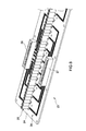
- an antenna 14 (without its protective case) according to the invention with only eight transducers, referenced as a whole, but it is understood that in reality, an antenna generally comprises a larger number at least 64.
- These transducers 15 have been shown in alignment, but it is also understood that in reality, they are not necessarily aligned, and their arrangement on the printed circuit supporting them is functionally, so known per se, characteristics of the acoustic beam to obtain.
- the transducers 15 are fixed on a plate 16 on which are printed electrical connection conductors between the different transducers and a connector (Not shown) providing, with another connector (not shown either) the connection with appropriate reception and signal processing circuits, well known per se and not described here.
- the conductors 17 printed on the upper face of the plate 16 each comprise a circular portion surrounding the fixing bore of the transducer, ensuring contact with a first front electrode of the corresponding ceramic, and extending by a filiform portion extending to a zone 18A where these conductors 17 are connected to through the plate 16, in a zone 18B (opposite the zone 18A) of the lower face of the plate 16, to sections of conductors 19 whose ends are welded to a connector (not shown, of which one has only shown the trace 20 on the plate 16).
- Conductors 21 are printed on the underside of the plate 16.
- the antenna 23 represented in figure 8 essentially comprises a printed circuit board 24 on which are fixed 64 transducers referenced 25 as a whole. Four connectors (of which only two, referenced 26, 27 are visible in the figure) are fixed on the plate 24.
- the printed circuit 24 is of the double-sided type, and therefore only sees in the figure the tracks 28 printed on one of them. his faces.
- the assembly is fixed in a sealed housing (not shown). Similarly, the electronic circuits (preamplification, amplification, pretreatment, ...) that can be included in this package have not been shown either.
- the cross-talking vibratory couplings that can appear via the printed circuit are minimized by optimization of the operation by the finite element method, by optimizing the mass of each element of each transducer, in particular the against the masses (10), so as to bring the nodal point of vibration of the structure to the printed circuit board in order to reduce as much as possible the deformation of the latter and the possible minute displacements of the transducers on their support plate (generally, the transducer fixing rod on the printed circuit board is much more elastic than the ceramic, and the prestress it exerts on the transducer is not sufficient to clamp it, but is sufficient to ensure the electrical contact between the elements of the transducers and the printed circuit).
- the structure of each transducer is represented as a mesh of small volume elements in which each of the acoustic quantities is calculated, knowing the initial conditions and the boundary conditions and applying the Kirchhoff theorem.
Landscapes
- Engineering & Computer Science (AREA)
- Mechanical Engineering (AREA)
- Transducers For Ultrasonic Waves (AREA)
- Obtaining Desirable Characteristics In Audible-Bandwidth Transducers (AREA)
- Waveguide Aerials (AREA)
- Variable-Direction Aerials And Aerial Arrays (AREA)
Applications Claiming Priority (2)
| Application Number | Priority Date | Filing Date | Title |
|---|---|---|---|
| FR0802548A FR2931016B1 (fr) | 2008-05-07 | 2008-05-07 | Antenne acoustique a circuits imprimes integres |
| PCT/FR2009/050842 WO2009141569A2 (fr) | 2008-05-07 | 2009-05-06 | Antenne acoustique a circuits imprimes integres |
Publications (2)
| Publication Number | Publication Date |
|---|---|
| EP2276583A2 EP2276583A2 (fr) | 2011-01-26 |
| EP2276583B1 true EP2276583B1 (fr) | 2015-08-26 |
Family
ID=40090003
Family Applications (1)
| Application Number | Title | Priority Date | Filing Date |
|---|---|---|---|
| EP09750050.8A Active EP2276583B1 (fr) | 2008-05-07 | 2009-05-06 | Antenne acoustique a circuits imprimes integres |
Country Status (6)
| Country | Link |
|---|---|
| US (1) | US9114427B2 (da) |
| EP (1) | EP2276583B1 (da) |
| JP (1) | JP5723765B2 (da) |
| DK (1) | DK2276583T3 (da) |
| FR (1) | FR2931016B1 (da) |
| WO (1) | WO2009141569A2 (da) |
Family Cites Families (11)
| Publication number | Priority date | Publication date | Assignee | Title |
|---|---|---|---|---|
| US3370186A (en) * | 1965-02-05 | 1968-02-20 | Blackstone Corp | Ultrasonic transducers |
| US3739327A (en) * | 1970-12-16 | 1973-06-12 | Dynamics Corp Massa Div | Electroacoustic transducers of the mass loaded vibratile piston type |
| JPS513886A (ja) * | 1974-06-29 | 1976-01-13 | Nippon Electric Co | Itsutankoteitategatashindoshi |
| US4373143A (en) * | 1980-10-03 | 1983-02-08 | The United States Of America As Represented By The Secretary Of The Navy | Parametric dual mode transducer |
| US6016821A (en) * | 1996-09-24 | 2000-01-25 | Puskas; William L. | Systems and methods for ultrasonically processing delicate parts |
| US4545041A (en) * | 1982-10-27 | 1985-10-01 | The United States Of America As Represented By The Secretary Of The Navy | Shock-hardened hydrophone |
| JPS59101593U (ja) * | 1982-12-24 | 1984-07-09 | 日本電気株式会社 | 振動子配列構造体 |
| JPH0523268Y2 (da) * | 1986-10-29 | 1993-06-15 | ||
| US5998908A (en) * | 1996-05-09 | 1999-12-07 | Crest Ultrasonics Corp. | Transducer assembly having ceramic structure |
| DE19620133C2 (de) * | 1996-05-18 | 2001-09-13 | Endress Hauser Gmbh Co | Schall- oder Ultraschallsensor |
| JP3961903B2 (ja) * | 2002-08-21 | 2007-08-22 | 古野電気株式会社 | 超音波振動子 |
-
2008
- 2008-05-07 FR FR0802548A patent/FR2931016B1/fr active Active
-
2009
- 2009-05-06 WO PCT/FR2009/050842 patent/WO2009141569A2/fr not_active Ceased
- 2009-05-06 EP EP09750050.8A patent/EP2276583B1/fr active Active
- 2009-05-06 US US12/991,033 patent/US9114427B2/en active Active
- 2009-05-06 JP JP2011507975A patent/JP5723765B2/ja active Active
- 2009-05-06 DK DK09750050.8T patent/DK2276583T3/da active
Also Published As
| Publication number | Publication date |
|---|---|
| WO2009141569A2 (fr) | 2009-11-26 |
| FR2931016A1 (fr) | 2009-11-13 |
| JP5723765B2 (ja) | 2015-05-27 |
| JP2011520374A (ja) | 2011-07-14 |
| WO2009141569A3 (fr) | 2010-03-11 |
| US20110051969A1 (en) | 2011-03-03 |
| EP2276583A2 (fr) | 2011-01-26 |
| DK2276583T3 (da) | 2015-11-16 |
| FR2931016B1 (fr) | 2010-08-13 |
| US9114427B2 (en) | 2015-08-25 |
Similar Documents
| Publication | Publication Date | Title |
|---|---|---|
| US8537640B2 (en) | Active sonar system | |
| EP2526705B1 (fr) | Structure de haut-parleur électrodynamique à technologie mems | |
| FR2971650A1 (fr) | Didspositif de conversion d'energie mecanique en energie electrique optimise | |
| FR2755303A1 (fr) | Antenne de champ magnetique blindee en circuit imprime | |
| FR2556165A1 (fr) | Reseau d'hydrophones en polymere a couches multiples | |
| EP1902453B1 (fr) | Dispositif capacitif a volume capacitif optimise | |
| FR2485857A1 (fr) | Sonde ultrasonore multi-elements et son procede de fabrication | |
| US6739203B1 (en) | Ultrasonic transducer and flow sensor configuration | |
| EP2276583B1 (fr) | Antenne acoustique a circuits imprimes integres | |
| EP3490727A1 (fr) | Transducteur ultrasonore multiéléments capacitif à couplage air | |
| JP3612312B2 (ja) | 超音波探触子及びその製造方法 | |
| EP0118329A2 (fr) | Hydrophone de vitesse | |
| EP3014606B1 (fr) | Transducteur à ultrasons | |
| WO2020240104A1 (fr) | Transducteur electroacoustique capacitif ultrasonore miniaturise fonctionnant a haute tension | |
| CN108291926B (zh) | 加速度测量仪和制造这种加速度测量仪的方法 | |
| US20130026884A1 (en) | Ultrasonic sensor | |
| WO2001068273A1 (fr) | Sonde acoustique unidirectionnelle et procede de fabrication | |
| US6561034B2 (en) | Ultrasonic sparse imaging array | |
| FR2689675A1 (fr) | Procédé pour amortir des ondes électromagnétiques, notamment dans une enceinte de Faraday et enceinte ainsi obtenue. | |
| CN103562731A (zh) | 加速度传感器 | |
| EP3179527B1 (en) | A tranducer with connectors soldered thereon | |
| FR3100806A1 (fr) | Dispositif de conversion d’energie mecanique en energie electrique fonctionnant sur une gamme de frequence de vibration elargie | |
| EP2568492B1 (fr) | Pièce d'interface entre une carte électronique et son panneau de commande, interface mécanique formée d'une ou plusieurs des dites pièces et dispositif comprenant une telle interface mécanique | |
| FR2938780A1 (fr) | Ensemble a transducteur piezo-electrique a connexions electriques perfectionnees, emetteur ou recepteur sonore et dispositif capteur de detection de choc ou pincement d'un obstacle ainsi equipes. | |
| EP1027731A2 (fr) | Procede de liaison et support de connexion d'un boitier csp avec un circuit integre |
Legal Events
| Date | Code | Title | Description |
|---|---|---|---|
| PUAI | Public reference made under article 153(3) epc to a published international application that has entered the european phase |
Free format text: ORIGINAL CODE: 0009012 |
|
| 17P | Request for examination filed |
Effective date: 20101104 |
|
| AK | Designated contracting states |
Kind code of ref document: A2 Designated state(s): AT BE BG CH CY CZ DE DK EE ES FI FR GB GR HR HU IE IS IT LI LT LU LV MC MK MT NL NO PL PT RO SE SI SK TR |
|
| AX | Request for extension of the european patent |
Extension state: AL BA RS |
|
| RIN1 | Information on inventor provided before grant (corrected) |
Inventor name: GROSSO, GILLES Inventor name: MOSCA, FREDERIC |
|
| 17Q | First examination report despatched |
Effective date: 20110413 |
|
| RIN1 | Information on inventor provided before grant (corrected) |
Inventor name: GROSSO, GILLES Inventor name: MOSCA, FREDERIC |
|
| RAP1 | Party data changed (applicant data changed or rights of an application transferred) |
Owner name: IXBLUE |
|
| DAX | Request for extension of the european patent (deleted) | ||
| GRAP | Despatch of communication of intention to grant a patent |
Free format text: ORIGINAL CODE: EPIDOSNIGR1 |
|
| INTG | Intention to grant announced |
Effective date: 20150413 |
|
| GRAS | Grant fee paid |
Free format text: ORIGINAL CODE: EPIDOSNIGR3 |
|
| GRAA | (expected) grant |
Free format text: ORIGINAL CODE: 0009210 |
|
| AK | Designated contracting states |
Kind code of ref document: B1 Designated state(s): AT BE BG CH CY CZ DE DK EE ES FI FR GB GR HR HU IE IS IT LI LT LU LV MC MK MT NL NO PL PT RO SE SI SK TR |
|
| REG | Reference to a national code |
Ref country code: GB Ref legal event code: FG4D Free format text: NOT ENGLISH |
|
| REG | Reference to a national code |
Ref country code: CH Ref legal event code: EP |
|
| REG | Reference to a national code |
Ref country code: AT Ref legal event code: REF Ref document number: 744858 Country of ref document: AT Kind code of ref document: T Effective date: 20150915 |
|
| REG | Reference to a national code |
Ref country code: IE Ref legal event code: FG4D Free format text: LANGUAGE OF EP DOCUMENT: FRENCH |
|
| REG | Reference to a national code |
Ref country code: DE Ref legal event code: R096 Ref document number: 602009033186 Country of ref document: DE |
|
| REG | Reference to a national code |
Ref country code: DK Ref legal event code: T3 Effective date: 20151110 |
|
| REG | Reference to a national code |
Ref country code: AT Ref legal event code: MK05 Ref document number: 744858 Country of ref document: AT Kind code of ref document: T Effective date: 20150826 |
|
| REG | Reference to a national code |
Ref country code: NO Ref legal event code: T2 Effective date: 20150826 |
|
| REG | Reference to a national code |
Ref country code: LT Ref legal event code: MG4D |
|
| PG25 | Lapsed in a contracting state [announced via postgrant information from national office to epo] |
Ref country code: FI Free format text: LAPSE BECAUSE OF FAILURE TO SUBMIT A TRANSLATION OF THE DESCRIPTION OR TO PAY THE FEE WITHIN THE PRESCRIBED TIME-LIMIT Effective date: 20150826 Ref country code: LV Free format text: LAPSE BECAUSE OF FAILURE TO SUBMIT A TRANSLATION OF THE DESCRIPTION OR TO PAY THE FEE WITHIN THE PRESCRIBED TIME-LIMIT Effective date: 20150826 Ref country code: GR Free format text: LAPSE BECAUSE OF FAILURE TO SUBMIT A TRANSLATION OF THE DESCRIPTION OR TO PAY THE FEE WITHIN THE PRESCRIBED TIME-LIMIT Effective date: 20151127 Ref country code: LT Free format text: LAPSE BECAUSE OF FAILURE TO SUBMIT A TRANSLATION OF THE DESCRIPTION OR TO PAY THE FEE WITHIN THE PRESCRIBED TIME-LIMIT Effective date: 20150826 |
|
| REG | Reference to a national code |
Ref country code: NL Ref legal event code: MP Effective date: 20150826 |
|
| PG25 | Lapsed in a contracting state [announced via postgrant information from national office to epo] |
Ref country code: IS Free format text: LAPSE BECAUSE OF FAILURE TO SUBMIT A TRANSLATION OF THE DESCRIPTION OR TO PAY THE FEE WITHIN THE PRESCRIBED TIME-LIMIT Effective date: 20151226 Ref country code: AT Free format text: LAPSE BECAUSE OF FAILURE TO SUBMIT A TRANSLATION OF THE DESCRIPTION OR TO PAY THE FEE WITHIN THE PRESCRIBED TIME-LIMIT Effective date: 20150826 Ref country code: PL Free format text: LAPSE BECAUSE OF FAILURE TO SUBMIT A TRANSLATION OF THE DESCRIPTION OR TO PAY THE FEE WITHIN THE PRESCRIBED TIME-LIMIT Effective date: 20150826 Ref country code: SE Free format text: LAPSE BECAUSE OF FAILURE TO SUBMIT A TRANSLATION OF THE DESCRIPTION OR TO PAY THE FEE WITHIN THE PRESCRIBED TIME-LIMIT Effective date: 20150826 Ref country code: PT Free format text: LAPSE BECAUSE OF FAILURE TO SUBMIT A TRANSLATION OF THE DESCRIPTION OR TO PAY THE FEE WITHIN THE PRESCRIBED TIME-LIMIT Effective date: 20151228 Ref country code: ES Free format text: LAPSE BECAUSE OF FAILURE TO SUBMIT A TRANSLATION OF THE DESCRIPTION OR TO PAY THE FEE WITHIN THE PRESCRIBED TIME-LIMIT Effective date: 20150826 Ref country code: HR Free format text: LAPSE BECAUSE OF FAILURE TO SUBMIT A TRANSLATION OF THE DESCRIPTION OR TO PAY THE FEE WITHIN THE PRESCRIBED TIME-LIMIT Effective date: 20150826 |
|
| REG | Reference to a national code |
Ref country code: FR Ref legal event code: PLFP Year of fee payment: 8 |
|
| PG25 | Lapsed in a contracting state [announced via postgrant information from national office to epo] |
Ref country code: NL Free format text: LAPSE BECAUSE OF FAILURE TO SUBMIT A TRANSLATION OF THE DESCRIPTION OR TO PAY THE FEE WITHIN THE PRESCRIBED TIME-LIMIT Effective date: 20150826 |
|
| PG25 | Lapsed in a contracting state [announced via postgrant information from national office to epo] |
Ref country code: SK Free format text: LAPSE BECAUSE OF FAILURE TO SUBMIT A TRANSLATION OF THE DESCRIPTION OR TO PAY THE FEE WITHIN THE PRESCRIBED TIME-LIMIT Effective date: 20150826 Ref country code: IT Free format text: LAPSE BECAUSE OF FAILURE TO SUBMIT A TRANSLATION OF THE DESCRIPTION OR TO PAY THE FEE WITHIN THE PRESCRIBED TIME-LIMIT Effective date: 20150826 Ref country code: CZ Free format text: LAPSE BECAUSE OF FAILURE TO SUBMIT A TRANSLATION OF THE DESCRIPTION OR TO PAY THE FEE WITHIN THE PRESCRIBED TIME-LIMIT Effective date: 20150826 Ref country code: EE Free format text: LAPSE BECAUSE OF FAILURE TO SUBMIT A TRANSLATION OF THE DESCRIPTION OR TO PAY THE FEE WITHIN THE PRESCRIBED TIME-LIMIT Effective date: 20150826 |
|
| REG | Reference to a national code |
Ref country code: DE Ref legal event code: R097 Ref document number: 602009033186 Country of ref document: DE |
|
| PG25 | Lapsed in a contracting state [announced via postgrant information from national office to epo] |
Ref country code: RO Free format text: LAPSE BECAUSE OF FAILURE TO SUBMIT A TRANSLATION OF THE DESCRIPTION OR TO PAY THE FEE WITHIN THE PRESCRIBED TIME-LIMIT Effective date: 20150826 |
|
| PLBE | No opposition filed within time limit |
Free format text: ORIGINAL CODE: 0009261 |
|
| STAA | Information on the status of an ep patent application or granted ep patent |
Free format text: STATUS: NO OPPOSITION FILED WITHIN TIME LIMIT |
|
| 26N | No opposition filed |
Effective date: 20160530 |
|
| PG25 | Lapsed in a contracting state [announced via postgrant information from national office to epo] |
Ref country code: SI Free format text: LAPSE BECAUSE OF FAILURE TO SUBMIT A TRANSLATION OF THE DESCRIPTION OR TO PAY THE FEE WITHIN THE PRESCRIBED TIME-LIMIT Effective date: 20150826 Ref country code: BE Free format text: LAPSE BECAUSE OF NON-PAYMENT OF DUE FEES Effective date: 20160531 |
|
| PG25 | Lapsed in a contracting state [announced via postgrant information from national office to epo] |
Ref country code: LU Free format text: LAPSE BECAUSE OF FAILURE TO SUBMIT A TRANSLATION OF THE DESCRIPTION OR TO PAY THE FEE WITHIN THE PRESCRIBED TIME-LIMIT Effective date: 20160506 |
|
| REG | Reference to a national code |
Ref country code: CH Ref legal event code: PL |
|
| PG25 | Lapsed in a contracting state [announced via postgrant information from national office to epo] |
Ref country code: LI Free format text: LAPSE BECAUSE OF NON-PAYMENT OF DUE FEES Effective date: 20160531 Ref country code: CH Free format text: LAPSE BECAUSE OF NON-PAYMENT OF DUE FEES Effective date: 20160531 |
|
| REG | Reference to a national code |
Ref country code: IE Ref legal event code: MM4A |
|
| REG | Reference to a national code |
Ref country code: FR Ref legal event code: PLFP Year of fee payment: 9 |
|
| PG25 | Lapsed in a contracting state [announced via postgrant information from national office to epo] |
Ref country code: IE Free format text: LAPSE BECAUSE OF NON-PAYMENT OF DUE FEES Effective date: 20160506 |
|
| REG | Reference to a national code |
Ref country code: FR Ref legal event code: PLFP Year of fee payment: 10 |
|
| PG25 | Lapsed in a contracting state [announced via postgrant information from national office to epo] |
Ref country code: CY Free format text: LAPSE BECAUSE OF FAILURE TO SUBMIT A TRANSLATION OF THE DESCRIPTION OR TO PAY THE FEE WITHIN THE PRESCRIBED TIME-LIMIT Effective date: 20150826 Ref country code: HU Free format text: LAPSE BECAUSE OF FAILURE TO SUBMIT A TRANSLATION OF THE DESCRIPTION OR TO PAY THE FEE WITHIN THE PRESCRIBED TIME-LIMIT; INVALID AB INITIO Effective date: 20090506 |
|
| PG25 | Lapsed in a contracting state [announced via postgrant information from national office to epo] |
Ref country code: MC Free format text: LAPSE BECAUSE OF FAILURE TO SUBMIT A TRANSLATION OF THE DESCRIPTION OR TO PAY THE FEE WITHIN THE PRESCRIBED TIME-LIMIT Effective date: 20150826 Ref country code: MK Free format text: LAPSE BECAUSE OF FAILURE TO SUBMIT A TRANSLATION OF THE DESCRIPTION OR TO PAY THE FEE WITHIN THE PRESCRIBED TIME-LIMIT Effective date: 20150826 Ref country code: TR Free format text: LAPSE BECAUSE OF FAILURE TO SUBMIT A TRANSLATION OF THE DESCRIPTION OR TO PAY THE FEE WITHIN THE PRESCRIBED TIME-LIMIT Effective date: 20150826 Ref country code: MT Free format text: LAPSE BECAUSE OF FAILURE TO SUBMIT A TRANSLATION OF THE DESCRIPTION OR TO PAY THE FEE WITHIN THE PRESCRIBED TIME-LIMIT Effective date: 20150826 |
|
| PG25 | Lapsed in a contracting state [announced via postgrant information from national office to epo] |
Ref country code: BG Free format text: LAPSE BECAUSE OF FAILURE TO SUBMIT A TRANSLATION OF THE DESCRIPTION OR TO PAY THE FEE WITHIN THE PRESCRIBED TIME-LIMIT Effective date: 20150826 |
|
| REG | Reference to a national code |
Ref country code: FR Ref legal event code: PLFP Year of fee payment: 15 |
|
| REG | Reference to a national code |
Ref country code: NO Ref legal event code: CHAD Owner name: EXAIL, FR |
|
| P01 | Opt-out of the competence of the unified patent court (upc) registered |
Effective date: 20230524 |
|
| REG | Reference to a national code |
Ref country code: DE Ref legal event code: R081 Ref document number: 602009033186 Country of ref document: DE Owner name: EXAIL SAS, FR Free format text: FORMER OWNER: IXBLUE, MARLY LE ROI, FR |
|
| PGFP | Annual fee paid to national office [announced via postgrant information from national office to epo] |
Ref country code: DE Payment date: 20250305 Year of fee payment: 17 |
|
| PGFP | Annual fee paid to national office [announced via postgrant information from national office to epo] |
Ref country code: NO Payment date: 20250523 Year of fee payment: 17 |
|
| PGFP | Annual fee paid to national office [announced via postgrant information from national office to epo] |
Ref country code: GB Payment date: 20260303 Year of fee payment: 18 |
|
| PGFP | Annual fee paid to national office [announced via postgrant information from national office to epo] |
Ref country code: DK Payment date: 20260306 Year of fee payment: 18 |
|
| PGFP | Annual fee paid to national office [announced via postgrant information from national office to epo] |
Ref country code: FR Payment date: 20260303 Year of fee payment: 18 |